In this article we investigate 4 simple yet powerful battery desulfator circuits, which can be used to effectively remove and prevent desulfation in lead acid batteries. The first method uses PWM pulses from a 555 PWM circuit, the second method implements an ordinary bridge rectifier for implementing a 100 Hz frequency based desulfation, the 3rd concept involves high voltage spikes, while the fourth design discusses desulfation using a 555 IC based high amplitude current pulsed circuit.
Sulphation in lead acid batteries is quite common and a big problem because the process completely hampers the efficiency of the battery. Charging a lead acid battery through PWM method is said to initiate desulfation, helping recover battery efficiency to some levels.
What is Sulphation in Lead Acid Batteries
Sulphation is a process where the sulfuric acid present inside lead acid batteries react with the plates overtime to form layers of white powder like substance over the plates.
This layer deposit seriously deteriorates the chemical actions inside the battery while charging or discharging making the battery inefficient with its power delivering capabilities.
Normally this happens when the battery is not being used for long periods and the charging, discharging processes are not done very frequently.
Unfortunately there's no effective way of tackling this problem, however it has been researched that the jammed sulphur deposits over an effected battery may be broken down to some extent by subjecting the battery to high current bursts while charging it.
These high current charging pulses should be well optimized through some control circuit and should be diagnosed carefully while implementing the process.
1) Using PWM
Implementing the method through PWM controlled circuit is probably the best way of doing it.
Here's an excerpt from wikipedia, which says,
" Desulfation is achieved by high current pulses produced between the terminals of the battery. This technique, also called pulse conditioning, breaks down the sulfate crystals that are formed on the battery plates. Short high current pulses tend to work best. Electronic circuits are used to regulate the pulses of different widths and frequency of high current pulses. These can also be used to automate the process since it takes a long period of time to desulfate a battery fully."
https://en.wikipedia.org/wiki/Talk%3ABattery_regenerator
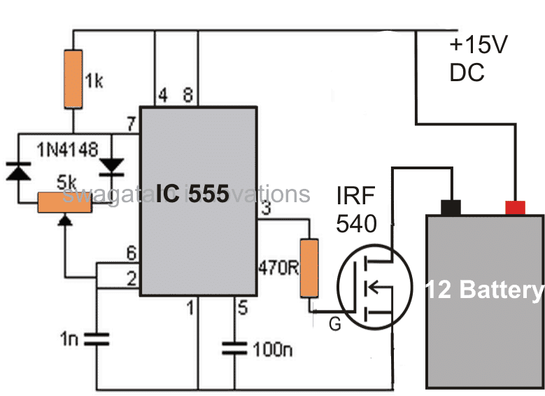
The circuit of a PWM battery charger discussed here can be considered as the best design for carrying out the above desulfation process.
How the Circuit Functions
The IC 555 is configured and used in its standard PWM control mode.
The output from the IC is appropriately amplified through a couple transistors so that it is able to deliver the said high current pulses to the battery which needs to be desulfated.
The PWM control may be set at low "mark" ratio for implementing a desulfation process.
Conversely if the circuit is intended to be used for charging normal batteries, the PWM control may be adjusted for generating pulses with equal mark/space ratios or as per the desired specs.
The controlling of the PWM will solely depend on an individuals personal preference, so should be done correctly as per the battery manufacturers instructions.
Failing to follow the correct procedures may lead to fatal accidents with the battery, due to a possible explosion of the battery.
An input current level equal to the battery AH level may be chosen initially, and reduced gradually if a positive response is detected from the battery.

Important Calculations
Frequency of the 555 Timer
We can see that the circuit operates in astable mode. The frequency is determined by the resistors and diodes connected to pins 6, 7, and 8, along with the timing capacitor.
Formula for Frequency:
f = 1.44 / ((R1 + 2 * R2) * C)
R1 = 1 kΩ
R2: Resistance of the 5k potentiometer adjusted along with the diodes
C = 1 nF (1 nF = 10-9 F)
Duty Cycle Calculation:
The diode configuration alters the charging and discharging paths.
Charging time (ton):
ton = 0.693 * (R1 + R2) * C
Discharging time (toff):
toff = 0.693 * R2 * C
Duty cycle (D):
D = (ton / (ton + toff)) * 100%
Gate Resistor (470Ω)
The 470Ω resistor limits the inrush current to the MOSFET's gate and prevents high-frequency ringing.
Gate charging time constant:
τg = Rg * Cgs
Where:
Rg = 470 Ω (gate resistor)
Cgs: Input capacitance of IRF540 (from datasheet, typical value ~1.2 nF)
IRF540 MOSFET
The MOSFET switches the high-frequency pulses to the battery. Its maximum current and voltage ratings must be selected to be higher than the load.
Power Dissipation:
P = I2 * RDS(on)
Where:
I: Current through the MOSFET (depends on the battery and load)
RDS(on): On-resistance of the MOSFET (typical value ~44 mΩ for IRF540)
Desulfation Pulse
The high-frequency pulse applied to the battery helps to break down the lead sulfate crystals. The frequency and amplitude are the critical aspects for the effective desulfation.
Pulse Voltage:
The pulse amplitude is approximately the supply voltage (15V DC) minus the MOSFETs VDS(on).
Pulse Current:
The peak current will depend on the battery internal resistance and the pulse width.
Capacitors (100nF and 1nF)
100nF (Pin 5): This capacitor Stabilizes the control voltage of the 555 timer and filters noise.
1nF (Timing): This capacitor determines the frequency with R1 and R2.
Notes:
You must choose or measure R2 (adjust the potentiometer for desired pulse frequency).
You can calculate the frequency and duty cycle using the above formulas.
Make sure to verify the MOSFETs current and power ratings against the load.
You can adjust the pulse frequency for the best desulfation results in the range of typically 1–10 kHz...
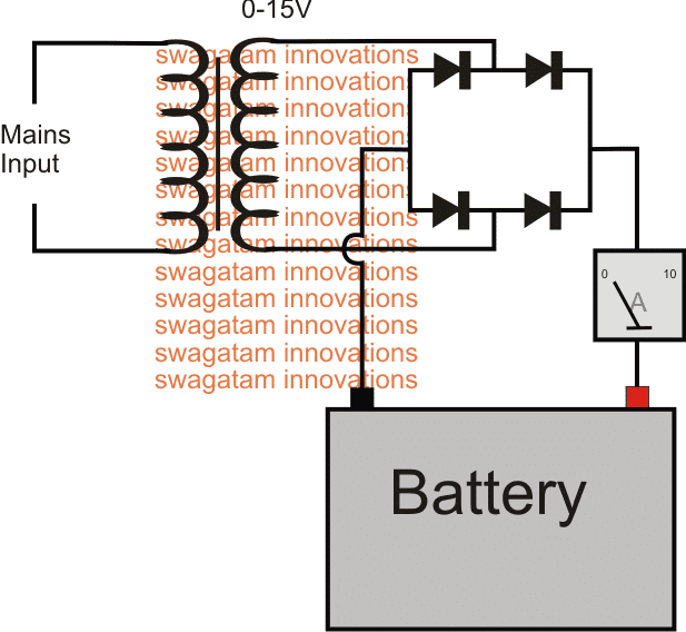
2) Desulfating with a Transformer and Bridge Rectifier Circuit
To make this simplest yet effective battery desulfator with charger circuit you would just require a suitably rated transformer, and a bridge rectifier. The design not only desulfates a battery, it keeps the new batteries from developing this issue and simultaneously charges them to the desired levels.
At the beginning of this post I have explained how to desulfate using PWM concept, however a deeper research shows that the process of desulfating a battery may not necessarily require a precision PWM circuit, the supply just needs to be oscillating at some given rate, and that's enough to initiate the desulfating process (in most cases)... provided the battery is still within the curing range and is not beyond the reviving state.
So what would you need to make this super simple battery desulfator circuit which will also charge the given battery, and additionally possess the ability to keep the new batteries from developing the sulfation issue?
A suitably rated transformer, a bridge rectifier and an ammeter are all that's needed for the purpose.
The transformer voltage must be rated approximately 25% more than the battery voltage rating, that is for a 12V battery a 15 to 16V supply may be used across the battery terminals.
The current can be approximately equal to the Ah rating of the battery for those which need to be revived and are badly sulfated, for the good batteries the charging current could be around 1/10th or 2/10th of their Ah rating. The bridge rectifier must be rated according to the specified or calculated charging levels.
Desulfator Schematic using Bridge Rectifier
How Bridge Rectifier Operates as a Desulfator
The diagram above shows the bare minimum requirement for the proposed battery desulfator with charger circuit.
We can see the most standard or rather crude AC to DC power supply set up, where the transformer steps down the mains voltage to 15V AC for the specified 12V battery.
Before it can reach the battery terminals, the 15V AC goes through the rectification process through the attached bridge rectifier module and gets converted into a full-wave 15V DC.
With a 220V mains input, the frequency before the bridge would be 50Hz (standard grid spec), and after rectification this is supposed to become double that is at 100Hz. For a 110V AC input this would be around 120Hz.
This happens because the bridge network inverts the lower half cycles of the stepped down AC and combines it with the upper half cycles, to finally produce a 100Hz or 120 Hz pulsating DC.
It is this pulsating DC which becomes responsible for shaking-up or knocking down the sulfate deposits on the internal plates of the particular battery.
For a good battery this 100 Hz pulsed charging supply ensures that the sulfation ceases to occur on the first place and thus helps to keep the plates relatively free from this issue.
You can also see an ammeter connected in series with the supply input, it provides a direct indication of he current consumption by the battery and provides a "LIVE update" of the charging procedure, and whether or not anything positive might be happening.
For good batteries this will provide the start to finish info regarding the charging process, that is initially the needle of the meter will indicate the specified charging rate by the battery and may be gradually expected to drop down to the zero mark, and that's when the charging supply needs to be disconnected.
A more sophisticated approach can be employed for enabling an automatic cut-off once the battery is fully charge by employing an opamp based automatic battery full charge cut off circuit (the second diagram).
3) Using High Voltage Pulse
The configuration detailed below provides the most up-to-date methods of desulfating lead-acid batteries. It is a circuit which routinely supplies quick yet intense pulses to the battery, while discharging the battery marginally between the pulses.
This technique, as much as recognized right now, is the best way to knock of undesirable build up of sulphate crystals and to bring back the battery plates into a good condition.
Because the voltage necessary for the high voltage pulses comes from the battery itself (this might appear a little bizarre initially, however the discharge of the battery is likewise a part of this technique), it is advised to hook up a charger in parallel with the battery and desulfator once the battery has not much capacity remaining.
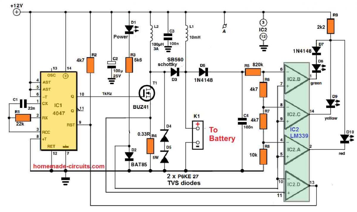
Pulse generator
It could be noticed in the circuit diagram that the parts needed for the desulphator tend to be extremely humble. The circuit consists of a couple of stages: a high voltage generator constructed using IC1, IC2d and T1, that generates the charging pulses, and an indicator circuit which involves not more than 3 op amps (IC2a, b, c) and three LEDs, that indicate exactly what condition the battery is in.
Let’s go through the pulse generator initially. Just like the other parts of the circuit, its supply voltage is obtained from the battery itself through K1. Although we’re discussing the supply voltage, this must have a pretty consistent voltage and should be devoid of any spikes (except those produced by the circuit itself).
Inductor L1 works like a suppressor, and is included in order to eliminate undesirable voltage spikes, along with C2 and C3 which work like smoothing capacitors.
LED D1 illuminates as soon as the supply voltage is switched ON. To proceed with the pulse generator, IC1 (a 4047) produces a square wave having a frequency of 1 kHz and a duty cycle which typically is 50 PERCENT. When the Q output of IC1 turns high, FET T1 switches ON. This results in a (discharge) current to move through the battery by means of L2, that boosts linearly until the voltage across R4 is approximately 0.35 V; the current can now be around 1 A.
At this instant comparator IC2d changes state, triggering IC1 to be reset and T1 to become switched off. The stashed magnetic energy inside L2 now gets converted to a voltage spike, which is inflicted to the battery through D3. How big the spike is can be determined by the condition of the battery.
If the battery is in a decent condition and its internal resistance is rather small, in that case the spike voltage level may also be reduced (under 15 V). In case the battery has a high internal resistance then the peak level of the spike could be as huge as 50 V. Its highest magnitude will be restricted and equal to the value of the two series connected zener diodes, D4 and D5.
LED Indicators
Considering that the health of the battery could be dependent on how big the charging pulses are, we have included a straightforward LED circuit which indicates the optimum value of the pulses. The 3 comparators IC2a-c evaluate the peak value inside C4 and changeover at voltages of 15, 20 and 30 V correspondingly.
Therefore in case the battery is in a reasonably good shape, the green LED (D8) illuminates, with a under-performing battery, the yellow LED (D9) lights up, and with an incredibly bad battery the red LED (D10) glows.
We have an information that needs to be pointed out regarding the indicator circuit: in order to prevent all three LEDs from illuminating simultaneously in response to a high peak voltage, they are attached in parallel to a single common series resistor (R9).
Since the red LED carries a smaller voltage drop compared to yellow LED, they may in no way illuminate together. But the yellow and green LEDs have got a identical voltage drop, so a similar technique will not do the job here, which explains why the green LED comes with an normal diode (D7), hooked up in series with it.
You will find three alternative methods through which the desulfator may be used. The first is to apply it within an existing system (inside a car as an example) to avoid sulphation from taking place inside a battery having minimum sulphation.
The advanced desulfator circuit is built-in with the system by hooking it up straight to the battery using shortest possible cabling. Because the circuit could be kept connected forever, absolutely nothing more needs to be done.
The current consumption is approximately 20 mA, therefore the battery might discharge in case it is not charged up from time to time. Recovery of batteries which have previously sulphated can be carried out in a couple of techniques. The first method would be to charge the battery, eliminate the charger and after that hook up the desulfator circuit.
Since the power for the charging pulses is derived directly from the battery itself, it is going to gradually discharge. This technique needs to be observed carefully because a completely discharged battery must be recharged quickly.
Most likely in real life many charge/discharge cycles will probably be necessary before a terribly sulphated battery could be restored to life. Since the approach described above needs a great deal of attention and has a danger that the battery could be left in a discharged condition unnecessarily (which can be extremely harmful to a lead acid battery!), another method can be perhaps much better.
The battery is coupled to the desulfator circuit, using a trickle charger hooked up in parallel. This implies, no chargers must be integrated that supply a current of 7 A or higher, yet one that provides a optimum of 1 or 2 A. This could be left coupled to the battery endlessly with no issues.
4) Using High Amplitude Pulsed Current from 555 Boost Circuit
We are not going to offer you a solution that will magically solve all the problems with lead batteries. However, the battery desulfator that we will describe in the following lines has proven its effectiveness, mainly in the United States for now, and the measurements we have been able to make on our model have been very promising. As it costs less than twenty euros, which is negligible compared to the price of a new high-quality battery, why not try it out and see for yourself?
Understanding Battery Chemistry
As you may know, a lead-acid battery involves a chemical reaction that can be written as follows during the discharge process:
Pb + 2H2SO4 + PbO2 -> PbSO4 + 2H2O + PbSO4
In other words, the porous lead of one electrode and the porous lead dioxide of the other are transformed, in contact with sulfuric acid, into lead sulfate and water.
Conversely, during charging, the chemical reaction that occurs is as follows:
PbSO4 + 2H2O + PbSO4 -> Pb + 2H2SO4 + PbO2
In other words, lead sulfate and water are transformed, under the effect of electric current, into lead, lead dioxide, and sulfuric acid.
The reaction is theoretically perfectly reversible, and that is why a battery of this type can be charged and discharged many times.
Unfortunately, over time and especially due to incomplete or poorly done recharges, the "reverse" reaction, i.e., the one that transforms lead sulfate into lead, is incomplete and leaves lead sulfate present on the surface of the battery electrodes or plates.
The phenomenon is unfortunately cumulative because, as this lead sulfate is a poor conductor, it tends to thicken where it has started to deposit, which only worsens the problem.
When the sulfation of a battery has reached a sufficient level, no traditional recharge process can overcome it.
Indeed, due to the poor conductivity of lead sulfate, the internal resistance of the battery increases, reducing its charging current and therefore the effectiveness of the charging chemical reaction, leaving even more lead sulfate present on the electrodes.
The resistance of the battery eventually becomes so high that it cannot hold a charge, meaning it can no longer supply significant current due to its excessively high internal resistance.
The Working Concept
This phenomenon has been known for a long time, and there is a chemical process that can be used to eliminate lead sulfate from a battery before it's too late.
However, it's delicate to implement and relatively dangerous due to the chemicals involved. In fact, the battery must be emptied of its electrolyte (corrosive!) to fill it with the cleaning product (also corrosive), and once this operation is complete, the battery must be refilled with fresh electrolyte.
The approach we propose is different and comes from various studies conducted in the United States on the influence of high-amplitude pulsed currents applied to a lead-acid battery.
According to these studies, and provided that very brief but high-amplitude impulses are applied to the battery, the lead sulfate crystals would gradually be broken down by the resulting ionic agitation occurring at the level of the plates and electrolyte of the battery.
This phenomenon is very slow, but since it can be achieved by simple electrical means, this process doesn't pose any particular problems as no manipulation is necessary on the battery being treated.
Circuit Description
The diagram that we propose is widespread on the internet on the other side of the Atlantic and, as far as we could verify, is attributed to Alastair Ocup. As you can see from in the following figure, it is relatively simple and has many similarities with a boost-type switching power supply.
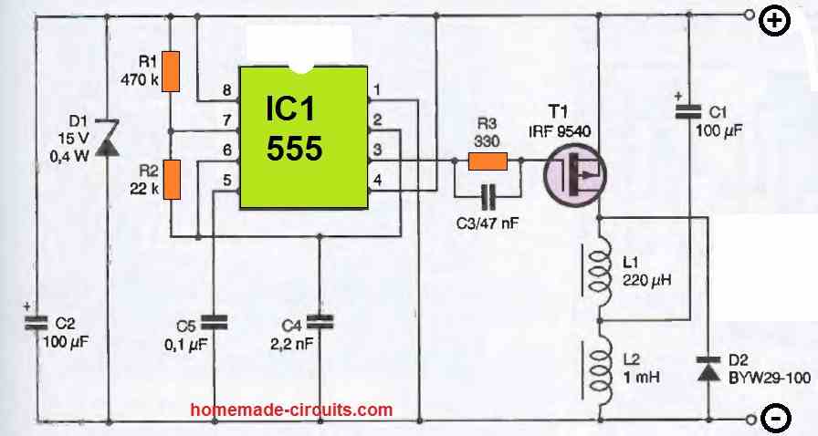
IC, which is nothing other than a classic 555, is configured as an astable oscillator operating at a frequency of around kHz. It produces very short duration pulses on its output available at pin 3.
When the level of these pulses blocks T1, capacitor C1 charges to the value of the battery voltage via inductor L2.
When T1 is made conductive, which only lasts for a brief moment due to the duty cycle of the pulses produced by IC1, capacitor C1 discharges abruptly across T1 and L1 since it is almost short-circuited by these components.
As soon as T1 is blocked again, the current generated by this discharge cannot abruptly cancel due to the presence of inductor L1. It is therefore sent to the battery via diode D2.
If capacitor C1 is of good quality and if the connection between the circuit and the battery is short and made of a suitable diameter wire, a current peak of the order of 5 to 10A can be obtained with a moderately sulfated battery.
Given the operating frequency of the 555 and the duty cycle of the signals it produces, the circuit's consumption remains relatively low and does not exceed an average value of 40mA
You need to get use a buffer between the 555 and mosfet for cleaner switching.
use a 7400 (CD series ic with all buffer paralled.
The first circuit on pwm desulfator, 555 calculator shows from analysis time High and low is about 0.00277ms frequency is 206 khz, the value I got from My design is 0.159ms for Time high/low each, frequency is 3.2khz. please help to compare these results. Thanks,
Different batteries may have different levels of sulfation, so estimating the PWM and the spike voltage can be difficult because the specs will be different for different batteries, that is why experimentation is necessary.
My goal is to make it as a charger to charge battery fast, so please what is your baseline guide in choice of appropriate parameters.
The charging conditions for aa sulfated battery cannot be predicted.
If you want a universal type of design, then you can build the design using IC 4047
Please any circuit as to this.
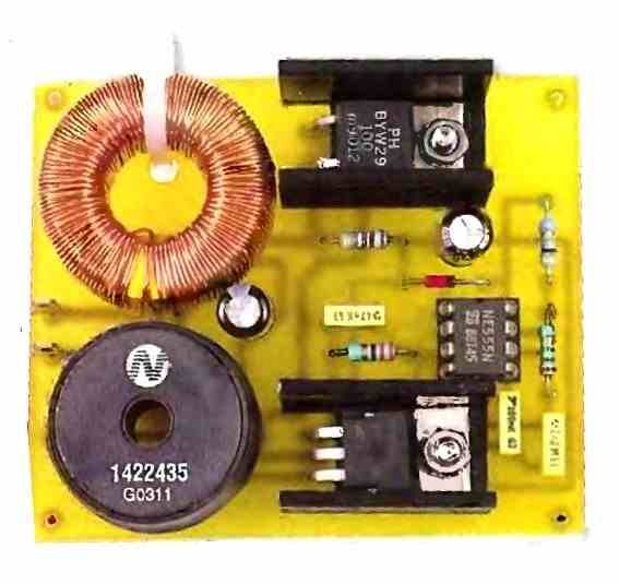
In the first 555 circuit, please connect a coil across the battery terminals, built using 200 turns of any thin magnet wire, over a ferrite rod.
Make sure to connect a 1N4007 diode across the drain source of the MOSFET.
The MOSFET can be replaced with a TIP35 transistor also.
Adjust PWM towards minimum and test the results.
I appreciate your response, should I use copper coil or aluminium coil as the thin magnet wire and what wire guage as the thin wire. What is the effect of this.
Always use copper coil, super enameled copper wire, 1 mm thick. The ferrite core rod can be 1 cm in diameter.
This will generate high voltage spikes across the battery, and hopefully break the sufation.
Hello sir, I made the pwm desulfator, which worked well with the 40ah LA battery. But I tried using same for 18ah la and lithium batteries, I had a fatal experience with explosions and damage to several 18ah la batteries.
Please how can I determine the appropriate pulse Value for the design to use for 18ah la and the lithium. Thanks Swagatam
Hello Daniel,
The rule is to use a low current and high voltage (PWM spikes).
If you use low current, there’s no way your battery can get damaged.
For a 12V 18 Ah you can try 200 mA or 500 mA 24V PWM spikes
Ok sir, how will I know the effect of the pulse in relation to the battery. I even used 20mA 19v for the battery.
Daniel, The exact magnitude cannot be estimated, it has to experimented through some trial and error. To can try low current voltage spikes of higher voltages upto 36V.
But 20mA is very less, it should be at least 200mA
Please what should be the recommended frequency range
Again that will need to be verified with some experimentation.
Please sir, how will I know the experimentation is giving positive results?
Hi Daniel, you will have to check the results by verifying how much the battery has charged.
Can desulfator used for lithium batteries
No, not on li-ion batteries, only on lead acid batteries.
Thanks,I will keep experimenting, is 60v 80mA bad for 12v battery
Hello sir, with 300mA, 35v, the charging is too slow at frequency of 16khz. Please how can I use the pulse charger for fast charging. Thanks.
Hello Daniel,
You will have to keep experimenting with the pulse PWM, frequency, and the voltage spike to find the optimal value, which can be different for different batteries. Alternatively, you can also try the following simple design:
" rel="ugc">
However if your battery does not respond at all, that would indicate the battery is almost dead.
I aim at pulse charger for fast charging not as desulfator, please guide
Pulse charging will not help in fast charging, a step-charging with initial high current charging will do the fast charging.
Hello sir, I made the first circuit and I found that for 60v design, it is better to use 5 separate 12v charger for each battery than a single 60v charger, please is there any modification in the circuit that will allow Me to use single charger for 60v. Thanks.
Hello Seun,
For a 60V battery, you can use a 60V supply for the MOSFET separately, and use a 12V supply separately to power the IC 555 stage.
Hi, Thanks for this. A couple of comments: The 2nd circuit should be attributed to Alastair Couper. not Ocup, and I think there should be series resistor in the positive supply rail to the 555, otherwise D1 and C2 will limit the output voltage pulse.
I agree with your comment about a series resistor to decouple the supply rail to the 555. As you say, without this D1 & C2 are effectively connected right across the output of the circuit. My homemade circuit board uses a 100Ω resistor for this.
Hi,
thanks for doing such a gr8 job designing, explaining the electronics with schematics and answering queries of so many visitors.
I was hoping you would be interested in designing a pulse charger for EV batteries. Obviously it’s not for desulphation but it’s widely accepted that PWM pulse charging is the best mechanism for fast and safe charging of EV batteries. It prevents dendritic formation and maximises efficiency. Rather than a continuous DC charge current, pulsed DC is best and it will enhance battery life and charge acceptance which is what EV users need. A CHARGE, DISCHARGE(for 100ms), SETTLE and MEASURE algorithm is needed. I hope this stirs your excellent creative genius.
Thanks for your valuable suggestion, appreciate it. Yes, pulse charging is actually good for all types of large chargeable batteries.
However, is there any critical algorithm for the ON/OFF duty cycle of the PWM, if yes then it could be difficult to design it using an analogue circuit. If not, then the first IC 555 based circuit can be configured to do the job very efficiently and very cheaply.
I have a question about the L1 in the 4047/339 version of these desulfators, it indicates a 10 mh value and I’ve been looking for a part # but not finding one. I see in the other version indicates a 1mh which is much easier to find. Does anyone have input on this?
L1 is easily available from most online electronic stores.
In this project, the current impulses from the L2 coil will discharge through the C2 and C3 capacitor to (-) of the battery, and through the circuit with the L1 coil. There is no other circuit with a battery. This can cause power voltage instability. Current impulses will also be heavily burdened with the C2 capacitor. Was that the purpose of this project?.
Yes, the purpose of the specified circuit is to create voltage spkes across the battery, to knock off the sulphated layers on the battery plates.
The question I have is in my case, I have 4x95a/hr deep cycles in parallel and they are all a little sulphated. I have them for an off grid power supply. I had a cheap PWM charge controller and it failed, so I replaced it with another of the same type which was at the time all I could get and afford until just the other day, So now I have a high quality MPPT which has made a major increase in the applied power from my 400w solar array. I have another 200w coming to add in in a few days. Anyhow, this has been the cloudiest year I’ve ever seen around my location, we can’t seem to get more than 2 to 3 days of sunshine then a week of clouds and rain. Would I need to build a circuit for each battery and connect it to each to give me a higher current output or would 1 circuit be able to recover all the batteries installed in the bank?
Yes you will need one circuit for each battery, or use a single circuit separately for each battery. The entire battery bank cannot be used with a single circuit.
Hi Swagatam;
I have scrap navigator equipment and it has 3,7 V battery inside. I think it is li-ion type battery. İt is possible to use desulfator charge method to charge that kind of batteries?
Regards
Hi Suat,
Li-ion batteries operate differently from lead-acid batteries and do not suffer from sulfation in the same way. Rather than sulfation, the principal degradation mechanisms of Li-ion batteries are capacity loss, electrode deterioration, and electrolyte breakdown over time.
As a result, the desulfation procedures utilized for lead-acid batteries are ineffective for Li-ion batteries. If a Li-ion battery is not working optimally or has lost capacity, it is usually better to replace it rather than try to desulfate it.
Good Afternoon!
Using a PWM desulfator, I have a string of 6x6v batteries and am desulfating two of the 6 in series. Does it matter which lead is connected to the actual battery under desulfation?
For instance, as it stands, Battery 1 is in series with battery 2 and as it stands, I have the positive lead connected to battery 2 and negative to battery 1.
Thanks!
Hi, I am not sure if I understood your setup correctly.
You have 6nos of 6V batteries in series, only two of them need desulfation, in that case you will have to remove those two batteries from the string and desulfate them separately.
I gotcha, just wondering if there was a dampening effect from having two batteries in series in the effectiveness of the circuit.
Thanks!
Yes, there would be a dampening effect causing inefficient desulfation.
Good day Sir, please can the 555 desulfator circuit that works for 40ah battery, will work for 200ah battery or any modifications
Hi Seun,
Yes it can be used for a 200Ah battery also.
Just make sure the current does not exceed 20 amps, but the voltage can be increased upto 20 V.
Keep the pulse width narrow initially and watch the progress with an voltmeter connected across the battery
So with the transformer and bridge rectifier what’s the difference between that circuit and a regular old style battery charger ?
The traditional battery chargers have a constant DC output which does not help to desulphate the battery, whereas the charger without a filter capacitor helps to charge the battery as well as keep the pates desulphated
Thank you for your reply I really appreciate your time. If I may ask another question please. Is it possible that I just remove the filter capacitor in an old 12v battety charger so I don’t have to find a transformer and other components, ” start from scratch ” scenario. I already have old 12v battery chargers. I appreciate your assistance I’m struggling financially from a bad accident and have to move to my off grid property before I’m properly prepared to so im trying to what I already have (isn’t much ) and get power and every thing else to survive immediately and then I can slow down and build better quality more sustainable infrastructure this is the reason why I ask these questions I can’t buy anything if I don’t absolutely need to or hire anybody to do anything for me I’m at the swimming part of sink or swim !!! Thank you
I understand your problem. I will try to answer your question.
If your existing battery chargers include an auto cut off system, then it may not be possible to eliminate the filter capacitor and convert it into a pulsed form.
If your chargers are ordinary type chargers, without a cut-off system, then definitely it may be possible to remove the filter capacitor from the bridge rectifier and make it compatible for the desulfation process.
The charger is a SEARS 8 amp/2 amp 12v it has a single 33Z1GET3 RED capacitor and a plate rectifier its an old unit can’t say much more about it. Hope this will work
OK, if it does not have any auto cut off circuitry, then you can easily get rid of the filter capacitor and use the pulsed output from the bridge to charge your battery.
Just make sure that the charger output is adjusted to around 14V peak and the current does not exceed 15% of your battery’s Ah rating.
Thank you sir very much for assistance I appreciate your time and for all that you do to share your acknowledge and expertise with us. God Bless you
Thank you, I am always glad to help!
the de-sulphator need to connect permanently with battery. The battery is inside the car. right now no any issue with battery. if I connect permanently, there will not be any issue right, and it will protect battery from de sulphate right.
There’s no problem if the battery is inside the car. Just make sure to use a charger whose maximum voltage is not above 14.5 V for a 12V battery.
I built the 555 timer pwm circuit but am a little confused. The schematic shows a + 15vdc supply applied to the Pos of the battery and to power the circuit. It doesn’t show where the negative of this supply is connected. Should it connect to Pin 1 of the timer?
I don’t understand how the circuit can work without the Neg of the external supply.
Thank you
Bruce
Yes, the negative of the supply must be connected to the line which joins pin#1 of the IC, the mosfet source pin, and the 1nF, 100nF capacitors.
Swagatam, here are the test results:
Using a transformer/rectifier as a desulfator/charger: The test circuit is a 120vac input to a step-down transformer with an open-circuit output of 16.7vac@10-amps which feeds a heat-sinked bridge rectifier rated at 50-amps.
The battery is a 4-year old car battery with a CCA (cold cranking amp) rating of 700 CCA. In order to get the Ah (Amp hour) rating you can divide the CCA by 7.25 to get a close Ah rating which in this case is 96.5Ah. So I want to see an initial charging current of 96.5/7.25= 13.3amps or less and an initial charge voltage of 14.2vdc maximum. The battery voltage measured 12.48vdc before connecting the desolator/charger circuit.
The initial voltage measured 15.8vdc (too high) and the initial current measured 9.3amps. In order to get the voltage to 14.2vdc I connected a variac to the AC input of the transformer and adjusted the variac to get 14.2vdc. The current dropped fairly quickly after 30-seconds from 9.3amps to 2.35amps @ 14.2vdc.
After 15-minutes the voltage increased to 14.3vdc and the current dropped to 1.48amps. At this point I re-adjusted the variac to get the charge voltage back to 14.2vdc. After 1-hour the voltage is back to 14.28vdc and the current is 1.45amps.
So my conclusion is that the battery is in good condition. I’ll continue to monitor the results and adjust the variac for several more hours. I’m expecting the desulfator to have an effect on the overall charge and maybe the voltage will increase from the initial 12.48vdc to a slightly higher voltage as a result of desulfation.
Jack
Thank you Jack, for the detailed feedback,
At 12.48V your battery already looks fully charged. However at 10 amp rate the full charge level shouldn’t have reached 14.3V in just 15 minutes, it should have taken at least half an hour.
Anyway, you seem to be right, the battery looks good to me.
It can be further verified only by discharging the battery at 10 amp rate and checking whether it lasts for at least 6 hours or not.
Thank you. I will set up a test circuit and post the results with the details of the initial battery voltage,
initial current, and so on for some data for others to see.
Jack
OK, no problem!
Hello Swagatam,
I want to try out the simple yet effective desulfation/charging circuit on my car battery. My transformer secondary open circuit voltage is 16.75vac and the unloaded rectified voltage is 14.8vdc. The bridge rectifier is rated at 50-amps and the transformer has unknown specs. but is rated at least 8-amps from what I do know about it and it’s physical size. I will use my multimeters 20-amp connections to serve as an amp meter. The car battery is near full-charge. My question is: What can I expect the initial current on the amp meter to show when I turn on the charger for the first time? Is the 14.8vdc voltage going to be high enough?
Thank you for your time,
Jack
Hello Jack,
The correct charging current should be 1/10th of the battery Ah rating. If your battery is not sulfated then make sure to apply this charging current to your battery.
If your battery is sulfated then you can use lower amount of current and a relatively higher voltage in the form of pulses to charge the battery.
For a good battrey the initial consumption will be almost the full charging current which will gradually get lower and lower as the battery reaches full charge level.
For a sulfated battery, it will depend on how the battery reacts to the pulses and how much it is able to desulfate and absorb the charging current, there’s no known value for this, will entirely depend on the battery condition.
The voltage for a good battery can be 14.8V but the charger should have a cut-off at 14.3V.
For a sulfated battery the current should be much lower but the voltage can be much higher and pulsed.
Hi Swagatham
I have an adapter that is 13.68 volts AC.
After rectification with a bridge rectifier only
( No smoothing capacitor), the voltage is 12.57 volts DC
I want to use this for charging my 12 volt battery which is apparently sulphated ( not being used for a long time)
When I connected this to the battery it quickly charges up to 14.4/14.6 volts ( Charging amps from about 850ma down to about 450 ma) and then I switched off the charger as I did not want to over charge the battery
Is there a way to keep the max charge at 13.9volts with this set up can I add an auto cut off circuit at 13.8/13.9 volts though this is only rectified with a capacitor or is there any other way to keep it at 13.8/13.9 volts and a low / trickle charge at say 20 to 50 ma
Kindly advise with a reply
Thanks and all the best to you
Hi Val,
I think you should try the following circuit for implementing the auto cut off:
" rel="ugc">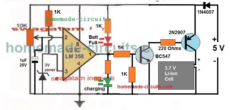
The 5V can be replaced with the voltage from your power supply source.
Please let me know if you have any further doubts or questions.
All the best to you.
Hi Swagatam;
Ref. to: above PWM desulfator circuit.
It is possible to use 1N4007 instead of 1n4148? And even if it is possible to make the same purpose circuit by no using any diode? I ask just to understand what’s going on between pin 7 and pins 2/6 when we use diodes there.
And my other question is:
I have no osciloscope then I can add an ampmeter to the circuit and adjust the pot 5K by proper current flow. Please advise if it is reasonable approach?
Regards
Hi Suat,
Yes 1N4148 can be used instead of 1N4007.
Using diodes provide better separation and control of the ON/OFF timing of the 555 output.
You can read the whole explanation n the following article:
https://www.homemade-circuits.com/how-to-use-ic-555-for-generating-pwm/
However you can build the same without the diodes also, as depicted in the following example concept:
https://www.homemade-circuits.com/dc-lamp-dimmer-circuit-using-ic-555/
You can use a DC voltmeter to check the average Dc output across pin#3 and ground. Lower voltage levels will indicate lower duty cycle or lower ON time and vice versa.
Hi Swagatam;
Ref. to your above PWM Controlled Circuit;
My battery group (13 x 1.2 V = 15.4 V and each 800 mAh) charging voltage is 18 V. On the other hand I have laptop transformer with 19 V and 3.42 A. It is possible use that transformer to charge the battery with the above PWM desulfator circuit. Best regards
Hi Suat,
Yes you can use the transformer DC with the PWM circuit to charge your batteries. Make sure to add a lamp in series to limit the current. Or you can build a LM317 current limiter circuit for the same purpose.
Thanks Swagatam;
However I need your confirmation for the belows;
– LM317 is current limiter or voltage regulator? Or you meant to adjust 19 V to 18 V. Then also possible to use a serial diode instead of LM317 to reduce the voltage?
– Also in case we use LM317, then the circuit will keep its being desulfator feature?
– If I use a lamp to limit the current, for instant I may use / add 12 V bulb in the circuit ?(since my transformer is 19 V)
Kind Regards
You are welcome Suat,
The LM317 can be actually configured separately as a voltage regulator or a current limiter or in a combined way to accomplish voltage regulation and current limiting both together.
In your case, a current limiting configuration will be quite enough.
Yes the desulfator will still retain and deliver its desulfating property depending on the battery condition.
Yes a 12V lamp can be also used in series for limiting the current.
Hi Swagatam;
I have cordless drill and its battery pack consists of 13 x 1,2 V 800 mAh batteries. That is about total 15.4 V and its charging voltage is 18 V. Please advise if that kind of batteries (shape like C size / type alkalin battery ) are rechargeable thru above desulfator circuit process / method.
Best Regards
Hi Suat,
I don’t think alkaline batteries should be recharged through any means. So according to me it may not be safe enough to try the above circuits to recharge or restore your alkaline batteries.
I am sorry but the batteries are absolutely rechargeable and not alkaline. I have written and used a definition as “alkaline” in my above message since just to describe that they are not like the type of car batteries and just to describe their size / volume. Also the drill is cordless and its charging voltage as 18 V is also written on its original sticker. So please be sure that they are rechargeable but my doubt is about to use desulfator method to those kind of batteries or not. Regards
In that case the above desulfator circuits can be tried on your battery. Just make sure to use low level of current initially, or use a filament lamp in series to safeguard from a catastrophic situation.
Hi Swagatam;
I have tested a battery charger circuit today.
DATA About circuit:
Input mains AC 220 V, before a bridge rectifier, a 50 mF capacitor which is connected serial.
Output voltage is DC 210 V after the bridge rectifier.
DATA about the battery:
12 V 105 A but voltage at the moment is about 10,8 Volt before charging process.
DATA while charging:
Voltage while charging on the battery poles is about 14,2 V and the current consumption by the battery is about 3,10 A (I think that may be about between 6 and 10 A if a 100 mF is replaced instead of the 50 mF capacitor)
My test period was about 1 hour then the battery voltage was about 12,8 V.
After all now I need your evaluation / critics and suggestions. Best Regards
Hi Suat,
50uF is huge and dangerous at 220V level for any 12V battery. It means you are supplying around 2.5 amps to your battery at 310V peak DC. I would not recommend more than 24V for any 12 V sulfated battery. It is difficult to evaluate the situation using 50 uF capacitor and 220V AC.
However if you are cutting off the charging after 14V then may be we can consider it safe for the battery but still 220V is never recommended for a 12V battery even if it is a sulfated one.
Hi Swagatam;
There is a software problem for me on this page due that I had sent an amendment message. This amendment awaiting and I am not able to sustain the subject.(there is no reply option or I can not see that choice below your latest message) My final question is : please advice about current values at the early stage of the charging. On the other words I will practise 8 V at first to charge my 6 V battery and include the ampermeter to the circuit. On this stage what should be the tolerable ampere value at the beginning I might read on the screen? Best Regards
Hi Suat,
the comment system can handle upto 10 comments per comment thread. Once 10 comments are full the reply link is no longer available. Your last amendment message was approved by me and posted.
The current will actually depend on your battery condition. If it is too bad and unresponsive then the ammeter will show very low current….if the battery condition improves then it might start drawing the full amount of current which is around 1 amp from your 8V transformer. For a 12V 12 Ah battery, 1 amp is quite tolerable.
Hi Swagatam;
Thank you very much for the previlidge about the 10 comments limit and I have charged one of my batteries was charged succesfully and be sure that next time my messages will be less than 10.
But my other one consumes 0,01 A while being charged by 8V and 0,18 A by while being charged by 15 V. So I have used the tranformer as its output is about 24 V. Now current consumtion is about 0,60 / 0,85 A at the beginning and if I add the headlamp bulb to the circuit then current gets lower to about 0,25 A at the beginning. Please advise if I should proceed with headbulb or not? Best Regards
Hi Suat,
After 10 replies you can start a new thread.
I think 24 V is too high for a 12 V battery (even though it is dead), therefore you must include a 12 V bulb in series to maintain extreme safety. It might take many hours of charging before the actual results can be seen.
after sending the message I have realized that the battery overheats. So I have added the bulb then charge current is 0,25 A and also I changed the transformer output to 14V and meausered the voltage over the battery poles as 12,38 DC Volt and now the current consumption is about 0,15 A. The other way is to apply to AC 220 V with capacitor. Or the batter is entirely hopeless? I need your comment. Best Regard
note : my battery is 6 V 12 A
Then a 12V transformer with a series bulb will be enough.
If the battery does not respond even after 15 hours of charging with 24V supply and a bulb in series, then the battery may be hopeless.
I won’t recommend using 220V through capacitor since it can be floating with AC mains and dangerous to touch.
Sorry about too many message that caused the complexity.
I have 2 pcs of 6 V 12 A batteries and one is charged succesfully and in a good condition. Second one has been charged in not 15 hours but only 2 hours period with 24 V supply. Upon overheating I did stop the charge process and measured battery vooltage over 6 V. But its capacity was weak as you may guess and then I made short contact to discharge it. Now I have been recharging it by 12 V and the current cunsumption is about 0,2 A. I will se the final result but if you advise me to stop and not to waste time then I will act as per your advise. Best Regards.
Glad to know that you could charge your batteries successfully. But two hours is simply not sufficient even for a good lead acid battery. It will require a minimum of 10 hours. So if your battery is getting charged in two hours that means it is not working, it is dead. Also, discharging a battery rapidly or by shorting can be extremely harmful to the battery and the battery may get damaged permanently, so please don’t discharge it quickly.
You can try charging it with a series bulb for 10 hours and check the results.
when charging the first battery with 8 V at the beginning current was about 1 A and it is dropped linearly to 0.2 A in a period of nearly one day. And I measured about almost 7 Volts. But now voltage is 12 V and there is serial bulb 12 V 5 Watt in the circuit and current is about 7 miliamp. I think that is too low. Now I should wait and see the result or quit I am really indesisive? Best Regards
The charging current will gradually reduce towards zero as the battery voltage reaches full charge level, so this is normal. It means your battery is getting charged. If your 6V battery has reached 7V it means it is fully charged.
sorry, ammendment:
For the my above message;
It should be “before the rectifier” instead of “after the rectifier”
Hi Swagatam;
My battery is 6V 12A and power is about 1 V at the moment since it is nearly dead or recovery is impossible I do not know. On the other hand, I have the sources 1) DC 12V 2A transformer 2) DC 12V 1A transformer 3) DC 25V 4A transformer 4) 14mF 250 V 50/60Hz 470kOhm/0.5W big capacitor and rectifier bridge diode (1000V 35A)
As a result for the above first 3 choices I can use 7809 and additional diodes in serial to decrease the voltage to about 7 V to charge battery with a 555 PWM circuit and I think also possible to charge by 220 AC for the above parts of item 4. I need your support and opinion. Best regards
Hi Suat,
Since your battery is completely dead it will probably require a pulsed DC for desulfating. You can perhaps try the 12V 1 A transformer and apply the voltage to the battery through a bridge rectifier without a filter capacitor. To limit the current you can use a 12V car headlamp bulb in series with the positive line. Using 7V DC might not help to revive the battery according to me. The bridge rectifier by itself will generate a good 100 Hz for helping the desulfating process.
Thanks for te support Swagatam;
I will try your advise however I have some 12 V car bulbs at home. One consumes about 2 A ann the other one does 0,5 A. Please advice one of them is good for me or I should find headlamp bulb. (I think its ampere is important and please mention how much ampere I should use) Regards
No problem Suat,
I think you should try the 0.5 A bulb first, if it does not help much then replace it with 2 A bulb and check the response.
I am sorry since I am confused and have missed some points on the following matters :
I should use the above first circuit with the IC555 or second choices as the circuit with the bridge rectifier?
And if it is better for me to use IC 555 circuit it is possible to use IRFZ44N instead of 540? And how I can use bridge rectifier to output of DC 12V adapter or I should add just 2 diodes to the DC output of the adapter?
Kind Regards
I recommended the bridge rectifier option since it is very easy configure and the results would be also favorable. For the rectifier option you will have to connect the bridge rectifier directly with the 12 V AC from the transformer as shown in the figure.
If you intend to use the 555 option then that is also fine, but for the 555 circuit you will need a pure 12 V DC supply, probably from an AC to DC adapter. You can use IRFZ44, no issues.
When comparing the above first circuit using pwm; I am able to understand that there is a pulse event since there are IC555 and ir540. in the circuit
However regarding the second one how it is possible to mention about pulse effect since AC is being altered to DC after bridge rectifier and as if it is not desulphating but normal charging process. Please can you explain the point that I missed. Best Regards.
The DC after the bridge is not a pure DC, it will have a 100 Hz ripple frequency. This 100 Hz ripple frequency helps to knock off the sulfation on the battery plates. The AC to DC after bridge rectifier becomes possible only once a high value filter capacitor is connected.
Thanks, I am gratefull and appreciate that valuable information. I have found a new transformer and its legs as output voltage have respectively AC 8 volts, 9,5 volts and 13 volts. And I think its current is lower than 1A. The my other transformers (2 A and 1A)above mentioned are in closed case and I can not gain AC voltage. So please advice which voltage is proper after the rectifier and stlill we need headlamp bulb in the circuit. Best Regards.
You are welcome Suat!
I think you can start with the 8V transformer, it will not require a bulb in series since the voltage and current are quite low. If it doesn’t work then you can try the other higher rated transformers step wise until hopefully you find some improvements. For voltages higher than 8V, a bulb should be included for appropriate safety.
Thank you Swagatham.
So for 12V tall tubular batteries, the spike pulse must be <20V (understood, will tune my circuit).
What about the frequency? which one is best suitable / resonant freq for desulphation? 1kHz / 10kHz / 120kHz ? Is higher the better? if so which is optimal to select?
Regards,
Muthu.
Hi Vairamuthu, sorry presently I do not seem to have the details with me regarding which resonance frequency will be most suitable for a battery desulfation. I will look for it, if found will update it here for you.
Thank you Swagatam. Yes, my ask was based on the latest circuit that I shared. What is the impact of 220uH -> 330uH inductor value change? I see pulse little widens for latter – is that all?
If I make PWM duty cycle to <8% (8% ON and 92% OFF) then no heat and doesn't need a fan, but the peak pulse measured on battery is around 20V or less but above 14V.
So question is what is the ideal peak value of pulses that must be applied to the battery for desulfation? what is the impact of frequency here. Basically I want to know what is best suitable frequency & pulse duty cycle & peak value of the pulse for best result on desulfation.
Also, is there a way to remove shorts within the tubular battery (one if the cell is partially seems shorted) – any suggestions?
Then, I was googling thru' some desulfator liquid (esp from this website: .ecoglobe21 dot com Japan engineers claims it is 100% efficient and doesn't need any extra electronic circuits for desulfation) – still searching where can I get this Ionic Functional water. While searching I came across this "Thermoil Battery Desulfator" – is this same as Japan folks claim – not sure – but still exploring.
Any good suggestions is highly appreciated.
Hi Vaiaramuthu, I received only the oscilloscope waveform through your email, the other image was not visible, was it from the above article?
Anyway there is no ideal value for the spike pulse level, because the desulfating level of different batteries can be different….but according to me for a 12V battery the spike pulse should not be beyond 20 V.
Sorry I do not have any idea regarding how the short circuit between the internal cells can be removed….will need to be researched only.
Hi Swagatham,
I modified the circuit a little bit as shared, Applied pulse width of 10% Duty of 8kHz and I am see this waveform on the simulator. Is this correct? please clarify.
What should be the peak of the pulse that gets applied on Battery? When I increase duty cycle the peak pulse voltage to battery increases (close to 46V) and MOSFET / schottky diode / Toroidal inductor gets heated up. Is this expected?
Thanks Muthu.
Hi Muthu, I guess you are referring to the last circuit. I have not tested it so can’t say much about the peak spike voltage from the inductor. I will suggest you to keep the PWM to a level where the inductor, mosfet and the diodes remain cooler. The peak is not critical actually, any value that comes out without heating the inductor and the associated parts should be a good value.
Dear Swagatam,
I want to use the circuit “Using High Voltage Pulse” for tubular batteries of 160Ah / 12V C10 type. If you have the proto type circuit board which you shown here or may be a bare pcb and components which I can assemble, then let me know how to purchase from you? Also suggest what changes need to be done on MOSFET / schottky diodes for higher AH batteries?
Dear Vairamuthu,
I am sorry, I do not have a PCB design for the mentioned project so it will be difficult for me to provide it to you. For a 160 Ah tubular lead acid battery, you will need to charge it at 0.1C rate, which is at around 16 amp current.
I saw your simulation results, as given below. It appears to be a basic boost converter circuit and should have worked. You can try removing the D3. D4, and the coil L2, and then check the results.
Dear sir,
Good evening, my name is Johnson oluugbenga, many thanks for your effort in putting so much of your time in solving our problem. I have an Idea of how to desulfator a deep cycle lead acid battery, it goes like this.
1. First open the cover on the cell
2. Put some distilled water into it to cover the cell
3. Apply one of your desulfator say the one with 4047.
Pls I hope I make some sense because I have been running away from deep cycle battery for long as it’s not easy to desulfator them. Thanks hope to hear from you sir.
Thank you Johnson, I appreciate your feedback, and I think what you are saying may be correct and must be tried to get better desulfating results.
Thanks sir for your quick response, am going to desufate one of my 200ah and I will post the results thanks God bless.
You are welcome Johnson, wish you all the best!
You might want to use a modified microwave transformer in the first circuit . Remove the secondary and put 14 turns of high current electrical wire in its place. Cheap and effective?
Thank you for the update, hope the readers find the suggestion useful!
Dear Sir
in the circuit “Using High Voltage Pulse” would you be kind enough to share details such as core
size, wire gauge in swg, number of turns etc. for the L1(10mH) and L2(100uH)3A inductors?
Thanks in advance.
Hello Imsa, L1 can be any small 10mH readymade inductor. L2 can be built using a 1 mm copper wire over an air core former. Keep experimenting until you get the indicated inductance value of 100uH.
Thank you very much… will try out and see if I can make it work….
You are welcome!
I am having 12v 120ah battey to inverter,but it is 9 years old so for I hadn’t done desulfation.I want connect first circuit along with 3 amp bridge rectifier.How to set the pot,what may be current
The adjustment of the pot is a trial and error process. You can use around 15 V as the supply input and use the minimum pot adjustment to get the minimum pwm output. Then charge the battery with this pwm for many hours and keep checking the response. If it doesn’t work, try increasing the PWM and so on….
Thank you for good information l will try this
Hi there,
Just build and made it work your circuit with IRF540. Desulphated my 12V 7 Ah battery. As I can not measure the frequency, I set the pot in the middle.
Prior to the desulphation checked the output close to 15 volts. Desulphation lasted about 2 hrs.
After desulphation twice, my battery is now working condition, lights the 25 watt car lamp for at least 30 minutes.
Thank you very much.
During the desulphation process, I measured that my battery draws around 7 amps. Is this OK or likely to be that way or not.
If you can answer this I will appreciate..
All the best.
Hi, glad you could use the concept successfully for your battery, however the main indication of a sulfated battery is that it won’t accept current properly, but you are saying that your battery is accepting 7 amp current which indicates that your battery may be already in a good condition??
And providing 7 amp current to a good 7 Ah battery can be extremely harmful for the battery.
So the results are contradicting.
So please first confirm whether your battery is really sulfated or not?
Hi, thank you for the answer
The battery was well sulfated for sure. It was 11.6 v and 0,03 amps before the desulphation..
The contradicting part is, during the process, amp drawing is quite high from the circuit. (I measured with multimeter, serial to battery on amps position). Since I am not an electronics engineer, I make these circuits and make some basic measurements. What I do not understand is if your circuit capable of giving high amperage with 15 volts dc to the battery ? If it is, then the circuit is fine and running. (as far as I see..it is.)
But for sure, my battery is well working fine after two rounds of desulphation. Thank you again for your answers.
Best regards
OK, it is good that your battery is working normally, but now make sure not to use more than 1 amp for charging the battery. For this you can either add a current limiter circuit to your power supply, or use a power supply which has a maximum output of 1 amps.
Ok, will do.
Thank you for the answers.
Have a great day.
Regards
Zafer abiden ögrendin yutubda?
I have a variable voltage transformer and thinking to use a single diode circuit to built a desulfater . Since only half of the ac waveform will be useful, should I use 32V ac voltage to drive the single diode desulfator? Will it be more or less effective than the bridge rectifier circuit? Thanks.
Single diode rectification will also work for desulfating a battery, however 32 V may not be recommended for a 12V battery….if you want to use a 32 V supply for a 12V battery you can connect a 24V series bulb to protect against accidental high current
please clarify what you mean by “The current can be approximately equal to the Ah rating of the battery” to help me size my circuit. For example with a battery rated at 10 Ah, what would be the required current through the battery? E.g. 1 amp for 10 hours? or 10 amps for 1 hour? My understanding of an Ah value is both an amperage X a time. Thus a 10 Ah battery could deliver 100 amps for 1 hour (theoretically). Ah does not specify a current. Thanks for your help. Your circuits are exciting and I would like to try desufonating some lead acid batteries using this method.
A 10 Ah lead acid battery can deliver 10 amp for 1 hour and that’s it maximum capacity, which will ultimately destroy the battery sooner or later, so this rate is not recommended for lead acid batteries, for Li-ion batteries it may be fine though.
I meant that for 10Ah, use 10 amp current, however this may be OK only for a deeply sulfated battery, so the exact rating is not predictable….you can start with a 1/10th of the Ah current rating and then increase to its full Ah level gradually, and this voltage must be pulsed using a PWM circuit as shown in the above diagrams.
Good day Sir, please does some batteries form sulfation more and faster than the other. Thanks
Seun, sulfation depends on the battery manufacturing quality and how it is charged and discharged
Meaning less quality battery sulfates faster and more than better quality, right.
that is correct….but using it badly can do greater damage….
Thanks for quick response. For lead acid battery, how often should one desulfate, and for how long in a day.
You must desulfate a battery only when its performance drops, otherwise no need to desulfate….however, using a pulsed charging can avoid a good battery from getting desulfated, and increase its life….and also make sure the battery is never over charged, which is a big reason for battery performance dropping and battery slowly desulfating.
Hi, my name is Dan. I’m a mechanic (retired) and I live in Elko BC Canada. I was wondering if you have tried a pulsed current with a small AC component to de-sulphate a battery? I know there would be some AC using a rectifier bridge (0.7V), but maybe a little more say 2 or 3 V at timed intervals. thx looking forward to your reply – Dan
Hi, no I haven’t tried adding an AC element with the pulsed DC, but it looks a good idea and can help enhance the effect.
Hi Swag;
Considering the desulfator circuit with 555/IRF540, I have got two questions;
1- If I would use IRFZ544 instead of IRF540?
2- My source is about 5 Amperes capacity however I am able to limit the curent. My battery is 60 or 72 Amperes. So, please advise which ampere I should let the desulfator to absorb it.
Thanks too much.
Hi Suat,
1) IRFZ544 will work
2) 5 amp is OK for 60 Ah battery.
you can increase the voltage to 16 V for greater effectiveness…
Swag por favor publique um carregador automático para bateria estacionaria com fonte de corrente constante .
Hi Lobrito, you can try the following design, it is current controlled:
https://www.homemade-circuits.com/regulated-car-battery-charger-circuit-for-garage-mechanics/
Hi Swagatam;
Considering above first circuit with 555 IC. I see some familiar circuits with 200 uH inductor. Please advise if that is better to use inductor in such desulfator circuits or not. My other question is how we can test the desulfator circuit if there is no osilloscope device. Thanks.
Hi Suat, inductors can produce sharp spikes of boosted voltage which might to some extent help speed up the desulfation, but there are no strong evidences confirming the facts. The results can be tested with meters, like ammeter or voltmeter. Initially, an ammeter may show no proper response but slowly it may start showing some current reading indicating that the battery is absorbing current and getting charged.
Please what is the effects of using two desulfators on one battery.
I don’t think that is required, and won’t have any different effect
Thanks Sir for your reply, pwm desulfator working well. More grace to your elbow.
What modifications are needed to make 48v desulfator.
Thanks Swag.
That’s great Seun, glad it is working! For 48 V, you will have to provide the 48 V separately to the battery and the MOSFET, and power the IC 555 circuit by stepping down the 48V DC through a 10k resistor, 12V zener, and a 100uF capacitor
Thanks so much Sir, please where can I put LED to light during pulsations
Between pin#3 and ground via a 1k resistor. but you cannot see it flashing since the frequency is too high…
If possible,I want to see it flashing
for flashing you can reduce the 555 frequency to 1 Hz.
Good day Swagatam, for 48v desulfator, which is more efficient 1 single or 2*24v desulfator
2 circuits cannot be used, only a single 48V circuit will be enough
Hi Swagatam;
I realized that my previous message is not logical. Please do not consider since the UPS would be damaged. Thanks again.
Hi Swagatam;
I’ve seen a desulfator circuit which consisting of 220 AC input with serial connected 18 mF 400 V AC capacitor and output DC high voltage (about 300V DC) and low amphere after rectifier bridge diode. My car battery will support my UPS device circuit and at the same time my UPS will desulfate the same battery.(in order that to keep ECU data on) Please advise if this no good idea. If so then please advise I may use the above circuit with 555 IC but IRFZ44N instead of IRF 540. Thanks
For the transformer based desulfator, at what battery level do I cut off the battery full using 15v DC charging voltage
At 14.4V
Please Sir, can I measure the pwm effect by a voltmeter
Yes you can, the voltage will be proportional to the duty cycle of the PWM
Thanks for your reply.
Please is it OK to also add pwm desulfator when trafo inverter
charging is already present to a new battery.
If you use a simple pulsating DC for the battery charging then the desulfation can be automatically implemented
Thanks Swag for this piece. Please is it possible to design the pwm prototype to be connected to battery only without using external power supply? If yes, how
Hi Seun, PWM circuit without a supply connected to battery?? sorry I did not understand your question…
Good day sir, please how many days can I use to desulphate a battery left for 3weeks. What discharge level can the battery reach. Is it charging and discharging or continuous charging will be effective. Thanks Swag
Sorry Adyemi, It can be difficult to predict or assess the results for batteries which are not in a proper condition.
helo sir can we use a 100hz IC555 astable circuit to make this battery desulfator. please guide on it
Any reasonable frequency can be tried, it is a matter of experimentation, there’s no mandatory rule for the frequency
Greetings, think I will be making one of these pending some information as in the following circuit, can you inform me of the missing connection. In the case of the trimmer resistor, can it be replaced with a single resistor, given that no test equipment/o-scope is available to tune. Pin 5 of the 555 timer doesn`t seem to go anywhere. I am leaning in the direction of pin 5 going to the 220k trimmer?
Thanks
The IC 555 circuit shown above is correct, pin5 must be terminated with a 10nF capacitor as indicated to avoid stray signal pick up. Single resistor is not recommended because you must have the facility to optimize the frequency to get the best results.
Hi
Can I de-couple two unequal batteries e.g. 1 – 12volt 90 a/hr battery and 1 – 85 a/hr battery with diodes but charge them from two separate chargers?
I have a caravan with a 90 a/hr battery wired into the internal circuits and I also have another 85 a/hr battery with it’s own charger. I would like to connect an inverter to both batteries in parallel thus having
175 a/hr at my disposal but only for the inverter. I would like to continue powering the rest of the 12 volt circuits from the original 12 volt 90 a/hr battery but would like to have the added possibility of not draining the original (90 a/hr) battery completely, thus leaving power to run the internal fridge, water pump, lights etc. if the drain from the inverter becomes exessive. I have access to dual 40 amp schottky diodes which I thought that I could implement for this purpose but I am not sure HOW.
As the available power from these two batteries is much, I don’t want to experiment with it but would prefer to find a tried and tested circuit. You can guess why!
Can you help, please?
Thanks and regards
Ivor Barnett
The assumed idea by you is possible. You can connect the anodes of the schottky diodes with the positive of the batteries, and join their cathodes with the inverter positive.
You can get a rough idea from this article:
https://www.homemade-circuits.com/parallel-battery-chargerchangeover/
How are you? I used diode 6A10, and it still gets very hot. with the 110v x 12v transformer. Thanks for your attention.
Hi, What is your battery Ah?
lead acid 60 AP
OK no problem, in that case the best way to avoid diode heating is to use a 5 amp transformer. This will never allow the maximum current exceed 5 amps, so your 6A10 will never heat up.
Please. which data can I use to make a diode bridge? Because all the bridges I made, it’s getting very hot, I even changed the 110v x 17v transformer, I replaced it with a 110v x 12v one anyway, it keeps getting very hot. So which diode can I use to make a diode rectifier bridge? thanks.
It means your battery is consuming too much current. By the way which diode did you use? you can try 6A4 and see the response
How are you doing? Please, the indicated full load cut-off circuit, you can receive these 15v, as it says 12V input, on the relays? Thanks.
You can use 14.5 V or 15 V with a 12 V relay, no problem with that.
Hi Swagatam,
Is it possible to design low cost battery-desulphator.
How much it cost if we go for bulk production.
will you help me.
Rohit
8288883678
Hi Rohit, the second circuit is the cheapest one…you can replace the bridge with a single diode to make it even cheaper
sir can i do this? add a 7812 regulator before pin 8 and 4 of 555, sorry i dont know how to attach a image here
Hi Jindro, yes you can add it, if your battery is rated at over 15V
Hi Swagatam. Your contribution to knowledge is highly appreciated. Kindly provide formula for calculating the pulse frequency for the circuit above.
Thank You Abdul. you can get all the required information , in the following post:
https://www.homemade-circuits.com/timer-ic-555-explained/
Thanks a million! Quite explicit.
Thanks! Happy to help!
Many thanks for this selfless service.
I will go through the circuitry and do the needful, while hoping that I will not come across any difficulty as I set off to prepare it.
Thanks.
No Problems!
Thanks a million times for finding time, out of your obviously tight schedule, to go through my mail and respond so urgently.
I wouldn’t mind a charging current that could be varied between the neighborhood of 0 to 20A .
Thank you, it’s my pleasure!! I have a power supply design which has this feature, you can find it here!
https://www.homemade-circuits.com/universal-variable-power-supply-circuit/
FRANKLY SPEAKING, YOU’RE REALLY DOING A GREAT JOB!!! SOMETIMES I WONDER HOW YOU GET REMUNERATED DOING ALL THESE…… MY WORRIES IS HOW TO GET A CHARGING CIRCUIT WITH ADJUSTABLE CHARGING CURRENT. PLS e-mail me.
Thank you! please specify the maximum charging current limit for the battery?
hello sir Swag .. is the circuit above whether it can be connected with car alternator with 60 Ah battery and if required fuse. thanks (sorry I use google translation ?)
Hello Edy, it may be possible if the alternator output is suitably rectified, filtered and regulated at around 15V
Thanks Mr. Swag
Hi Mr. Swag,
Thanks for the reply. I used the 1n5408 diodes in series. Would I measure the current at the output of the Mosfet or the output from the diodes?
Hi Peter, you can connect the meter in series with the positive supply line …anywhere…. the current must pass through the meter, that’s the requirement.
Hi Mr Swag,
I have now built the circuit with the diodes in series, but find that the diodes get very hot after about 10 minutes. The Ic and mosfet however do not. Is this normal?
I have checked for solder bridges and found none. Input to the diodes is 20vdc and to battery pos 15.2 VDC. Output from the mosfet drain is 12.4VDC. Any help will be appreciated.
Hi Peter, which diodes did you use? check the current consumption during the charging with a series ammeter and make sure to use diodes that is rated 2 times more than this measured current consumption
Hi Mr. Swag,
Hopefully the last question. Can I use a 7815 voltage regulator instead of the diodes? What would be advantages /disadvantages.
Many thanks
Hi Peter, you can use 7815, but it will allow only upto 1 amp current for the battery….
Thanks a lot. I will use that until I can get the diodes.
sure, you can.
Hi Mr. Swagatam, thanks for the very good information all over the site. I have an AC to 24v DC transformer and would like to know how to get the voltage down to 15v and can I then use that? Your help is much appreciated.
Hi Peter, you can add 12 to 14nos of 1N5408 diodes in series with the positive line, this will drop the 24V to 15V
Thanks Swag,
If I understand it is 12 1N 5408 in series?
Peter
yes that will do!
Thanks
it is not shown by mistake, but it's understood, otherwise how the circuit will work?
Faith,
I think you are not able see my replies because you are not pressing the "load more" button….unless you do this you won't be able to see the hidden replies.
your second question is very strange, and It can be difficult for me to figure out the solution until I check the circuit practically…
Sir please answer me let know way forward
I have already answered, please press the "load more" button to the hidden comments
Sir this what i observe i noticed that even when there is no gate voltage to the mosfet the battery is still charging i went as far removing the 555timer to confirm this and notice the battery was charging please what could be the cause and how to correct it thanks
Faith, I think your mosfet is already burnt, or was originally faulty….instead you can try a TIP35 BJT, because BJTs are normally more rugged than mosfets and do not get burnt mysteriously…
Hi you are the best
I made this charger and its really working thank you very much please how do i include cutoff to this circuit
thanks Faith, you can use the following circuit for the cut off
ttp://162.240.8.81/~homembc5/2011/12/self-regulating-lead-acid-battery.html
Again should my duty cycle be 95% or 100% advice is needed in this case
duty cycle can be a matter of experimentation , start with 50% initially
Thank u for the reply
Ok can connect mosfet in parallel so that the current can be shared among them.
secondly the circuit seem not to have charge control which means one needs to monitor the battery so that it dont get over charge if that be the case how can i add a cut of can i use this circuit
https://www.homemade-circuits.com/2013/03/automatic-lead-acid-battery-charger.html?m=1 from this your post
Again is the mosfet N-channel or p-channel
If N-channel is it the drain that gose to the negative of the battery? While source to ground
yes connecting the mosfets in parallel will also work to increase the amps.
I won't recommend the linked 555 based design, instead you ca use the following one
https://www.homemade-circuits.com/2011/12/self-regulating-lead-acid-battery.html
the mosfet shown in the above desulfator article is an N channel, and its source is connected with the negative line.
Sir I'm really proud of you for ur good works and quik response you are one in a million. Sir about the above circuit can it be use to charge a 12v@600AH and if yes what modifications should i do. secondly the circuit seem not to have charge control which means one needs to monitor the so that it dont get over charge if that be the case how can i add a cut of can i use this circuit https://www.homemade-circuits.com/2013/03/automatic-lead-acid-battery-charger.html?m=1 from this your post if yes how i attached ithttps://www.homemade-circuits.com/2013/03/automatic-lead-acid-battery-charger.html?m=1
Thank you Faith,
you can use the above circuit for charging any desired battery, through appropriate modifications in the mosfet value.
for your application you will need to replace the existing mosfet with a 100amp rated moefet…
it means your 555 is not working or a is faulty, replace the 5K pot with 100K and replace the pin6/2 capacitor with a 100uF, and check the output if it generates the pulses or not…if still not, then you may think about changing the IC
I just build it, but not work and then checked using an oscilloscope nothing pulse or voltage spike Yo the battery.
Adivice me, give solving about this problem.
sir, i want use led for pulse show in this circuit where i connect please help
connect it from pin#3 to ground through a 1K resistor, but the LED will appear continuously lit with any frequency higher than 4Hz
Hi swagatam please i need your help i have a 12v battery@200A and they are 4 in number connected in parallel and i want to make a charger for it, a charger that provide at least 80A for the battery connected in parallel please can you give me pulse width charger circuit with cut off that can handle such high current thanks
Hi Faith, the 80 amp is supposd to come from the transformer of the charger power supply….you can use any relay based automatic charger posted in this website and attach a 14V 100 amp power supply to its input for achieving the required results.
PWM is not required for this
Please can u give me the link to relay base automatic charger
you can try the following
https://www.homemade-circuits.com/2011/12/high-current-10-to-20-amp-automatic.html
can i use irf640 instead of irf540…..or is it work without toroid coils which are arranged in order to make hi pluses.. that is 1000uH and 200uH
torroid coil is not necessary….i am not sure about IRF640, if its current/voltage specs are compatible then it can be used
Can we use this circuit for sealed lead acid battery 6 volts please reply
yes can be tried…
cause mosfet need at least 5v to operate normally.
best regrads
IC 555 will produce a voltage that's exactly equal to the supply voltage, so in the above case the output will be 15V at pin3…not an issue for the mosfet.
hi mr swagatam,i hope you are good
i suggest to add a simple mosfet driver using a transistor cause 555 output voltage is weak and thus will overheat the mosfet,i tried before to connect 555 output to mosfet gate with a resistor and mosfet gets hot.
Hi Hisham, I am good thanks,
555 IC has an output that's more powerful than most ICs, however mosfets never require a powerful signal to operate, they just need a voltage above 9V for operating optimally.
You can try reducing the gate resistor to 10 ohms and check the response….or may be the load you have connected could be above the mosfet range
Interesting circuit. I had a thought, perhaps this could be combined with adding a very small (<3ml) of acid to each cell technique for unmucking dead SLAs typically run to death in UPSs.
If they are at 0.0V I doubt any technique will work but its the ones which have good voltage but next to no capacity that could be salvageable.
thanks for updating this info, appreciate it!
Thanks for circuit skema
is there any inductor on the above schematic ????
which simulator i can use to make this circuit and can have a dead battery in it for charging?
if you plz don't mind…can you plz send me the whole process from the begining till the battery desulphation.. what all the pins are doing … plz .. i will be gratefull to you.
simulation is not required, just procure the parts and the build the circuit, the circuit is explained in the articles itself…
Good day to you sir.
Thank you for sharing all the great work.
A few questions about this circuit :
1. What is the 5k POT for ? & how to adjust it ?
2. Does the IRF 540 need a heat sink ?
3. The negative of charger is directly connected to IC Pin #1 ?
4. How to connect a LED to this circuit, that illuminate when connect to battery ?
5. Any harm if connect to the battery permanently ?
Thanks a lot in advance .
Good day Alaa,
1) 5K is for playing with the output pulse width, which might in turn help to implement a optimal desulfating effect….it could be a matter of some trial and error and dependant on the connected battery condition. however it's not so crucial, you can keep it at the center to begin with
2) Normally it shouldn't require a heatsink, however you can test it practically by touching it, to be on a safer side..
3) yes the negative of the charger needs toeb connected to the pin#1 line of the IC
4) charging indication might not be possible, however an ammeter may be connected in series with the battery positive to get a direct reading regarding the batt response to the charging procedure.
5) yes if the battery begins responding and desulfating…an ammeter can be used for monitoring the same as explained in the above point
Thanks Sachin,
shorting would be advisable only if the battery has sufficient charge on it, unless it's charged fully, shorting won't induce any effect on the plates.
The pulse charger explained in the above article is the ultimate way of dealing with this mess, if the battery responds and wakes up to the pulsed charging only then the shorting of the terminals can be tried, however as shown in the video a high amp resistive load would be more appropriate than shorting since here we don't have to worry about the delay period in ms
Sir, I'm planning to add this circuit on my existing 72v ebike charger. It has 6 pcs.12v 20ah battery connected in series. Would it be possible? What ic regulator should I use for LM555's supply voltage? And what mosfet would you recommend?
Hi Jusi, yes you can try it, just make sure to disconnect the battery positive from the shown point and connect it with the +72V supply……..and connect the positive of the circuit with the positive of last 12V battery in the series which has its negative connected with the bike's ground or the bike's negative….
the negative of the circuit can be joined with this ground that is the common ground line.
Thanks Mikel,
changing 1nF to 1uF will reduce the frequency or the pulse rate, but that will not affect the results, so it's OK.
the mosfet and the supply voltage are also OK, but the current input must be well over 20 amps for desulfating a 100AH battery, so make sure the supply current is at this level.
Hi Mikel,
you can connect an LED across pin3 and ground with a series 1K resistor but it will appear continuously glowing due to high frequency pulses from the IC
Hi swagatam! What is the ideal mosfet for a below 20amp battery?
IRF540 is the ideal mosfet as shown in the diagram
Hi swagatam! Is there a need to change some parts of the circuit if my battery is ranging 7 to 14 amp?
Hi Josue,
no changes would be required for your mentioned application.
can we ad two LEDs to show it is charging and one for it is charged?
I've built the first circuit and when i connect the battery the coil heats up and smokes
please try the above circuit without the coil, the TIP122 will need to be upgraded if your battery AH is higher than 20AH
my battery is 80 AH
Can I use IRF540N instead of IRF540
IRF540N will do and will work for an 80AH battery
Hi,
I started building your old circuit and only realized you have changed them ,but I have bought parts for the old diagram,so can I build the circuit without the inductor with the TIP122 ,or should I Change it IRF540.
Hi, I changed the circuit a long time ago may be a half year ago, it's strange you are building it now.
I would recommend you to make the above shown design instead of the earlier one since adding a coil will not make much of a difference.
Hi Mr. Swagatam, newbee here.
So I've finished assembling the circuit, how to tell that it's working before I start attaching it to the battery? I mean is there some type of indication there or do i've to measure anything first?
thank you.
Hi Imanul,
There's no circuit which can guarantee a perfect desulfation in dead batteries, so you can only hope that this circuit produces the intended results as it's designed as per the standard recommended specifications.
Use the circuit for about 4 hours and then check the battery with an appropriate load, if the charge sustains for an appreciable amount of time you can assume it to be revived, otherwise you may repeat the procedure with some change in the PWM frequency and/or the input current to the circuit and check the response in a similar manner.
…please change the 1n caapcitor with a 10uF capacitor.
connect an LEd across pin3 and ground via a 1K resistor.
When switched ON this LED must flash rapidly indicating a proper functioning of the circuit, changing the pot would change the flash rate on this LEd
you can keep the new capacitor connected and use the circuit for the required purpose, it won't make any difference in the performance.
Is it possible to desulphate my 6v,5ah sealed lead acid battery by this ckt.
yes it's possible
How it to be possible?what changes in the ckt for 6v,5ah sla battery desulphating.and how much time taken to desulphate.
use 10V supply with 3 amp current,
use TIP122 instead of the mosfet
time is not known……. also the result may not be positive, will depend on how much your battery may be recoverable.
Thanks for your information.tell me the Pin connections of TIP122 while using instead of mosfet in this ckt.
pls check its datasheet
thank you I already done it just downloaded the ic pin out then I know the number 1 leg is the ground.
thank you again for your fast response and attention.
hi
I just realise in the circuit there is no ground to the circuit?
if we use power supply to connect to this circuit the plus 15V pole goes to the battery and the circuit where then the negative pole goes?
I know if I use coil and transistor I have to connect the negative pole to emitter but on mos fet not sure looks like this one joint missing from the circuit
could you please correct me if I am wrong?
The line connected with pin#1 of the IC is the negative line and must be connected with the power supply negative.
So Avenger is saying that there is no coming back from hard crystalline PbSO4 .
OUCH!
One should have all batteries under full time trickle charge.
Avenger ,…. which one of Swagatam's designs did you use for your charger?
Carl
Lead Lead Sulfate PbSO4 is part of battery charge discharge cycle. The structural form of PbSo4 makes the difference. While amorphous PbSo4 is reversible while hard crystalline PbSO4 is irreversible and inactive. Shallow cycle batteries never have to be discharged under 12.5 volts. If this happens an immediate charge will consume and transform PbSO4 in to Pb, H2O, PbO2 and H2So4. If let staying there for sometime the PbSO4 crystallize and turns inactive. To make a long story short if battery isn’t in use immediately use Float charging with a battery trickle. Harbor freight tools sell a battery trickle (Floater) for $9.99, which I bought on sale for $6.0. The manufacturer 13.2Volts was only a promise, but replacing VR1 with a 100-Ohm trim pot, I can adjust the voltage from 12.6V to 14.25V. I set it at 13.25V but this is only the first aid. What you need is EQUALIZE the BATTERY; this can be done at 14.5V for some hours. During this process the strong cells start boiling but the weakest cells continue charging. This can be done with a battery tender. I bought one from Wal-Mart connected to my VW Touareg and the next day the relay was chattering ON / OF non-stop. Measured Voltage a found 14.85 Volts. The electronic system of the car was fighting hard against this stupid tender. I solved the problem building up my Battery Tender with precision voltage Window 14.5V stop charging and 12.6V restart charging giving the battery a chance to rest, RELAX. Charging a discharged battery you have to deal with Bulk Charge Current Density that depends from electrode surface and is expressed on mA / Cm2. If a have to deal with an accidentally fully discharged battery I use my Automatic Smart Battery Charger, with Equalizing and reconditioning features.
how can i indigate this is working correctly irf 540 get heat?
Hello Swagatam,
I would like to build a hi/lo adjustable relay/contactor.
Say ….12v on 13.5 off
I could then put it in series with any charger.
It would be great for maintenance and prevent over charging.
A variant of this could also kick in a discharge cycle.
This would be good for desulfating.
Do you have a design lik this?
Yours
Carl
Hello Carl,
Please see the last diagram in the following link, it'll fit your need well:
https://www.homemade-circuits.com/2011/12/how-to-make-simple-low-battery-voltage.html
The second relay shown is not relevant, you may remove it.
Hi Swagatam
Since I was focusing only on the mosfet so I didn't gave you the details of the other sections.
As mentioned earlier, one cycle consists of mainly 3 steps + 1 step to monitor battery voltage. Each step is controlled by a 555 and another 555 is controlling all these 4 ICs (the entire cycle). If you want to have a look at the circuit, here it is.
" rel="nofollow ugc">
I am sorry, that is maximum available resolution of the picture.
Now, I repeat my question in other way. If the mosfet can be driven directly by the 555, why the author deployed 0.8A transistors to drive the mosfet. You can find them at the top-right corner. I haven't linked the website as per your general instruction however, if you want to see the circuit description I can send you the link.
Hi Abu-afss,
It could be for allowing the mosfet to conduct and restrict correctly, especially the use of the push-pull (PNP/NPN) stage which ensures safe charge/discharge of the internal cap of the mosfet, because as we all know how sensitive these mosfets can be at times.
Hi Swagatam 🙂
One complete cycle includes 3 steps:
1) 15 sec pulse charging
2) 1 sec delay for settling
3) 100ms shorting battery terminals
I am just curious about the driving of the mosfet as I asked in my previous post.
Hi Abu-Hafss 🙂 how are these three steps implemented because i can see only one active input from the IC 555.
I wanted to know the relevance of the transistor stages for answering your question correctly.
Normally we know that a mosfet gate can be integrated with any IC output may it be a 555, a cmos or a opamp, as long as the voltage is below 15V
Hi Swagatam
I came across a desulfator circuit which, apart from the regular desulfation process, also shorts momentarily battery terminals as shown here:
" rel="nofollow ugc">
I want to know, couldn't the signal from the 555 pin#3 be directly fed to the gate of the mosfet (point A) or at point B?
Hi Abu-Hafss,
How does this circuit desulfate…is it by charging and shorting the battery alternately? I could not understand the concept.
Hi Swagatam
I have read some of above posts talking about an inductor L1. Where is that inductor, I can't see it in the circuit or any reference in your article?
By the way, I am working on a trickle charge desulfator. I am considering to integrate a circuit to measure battery's internal resistance (BIR). There are a few BIR measuring circuits on the net but, they need to take occasional measurement manually. Here are two of them:
" rel="nofollow ugc">

" rel="nofollow ugc">
My idea is to have three-LED indication……..the red LED to indicate high resistance, yellow to indicate medium and green for very low resistance. The BIR circuit will operate in parallel with the desulfator circuit. The illumination of the green LED would indicate that the battery has been desulfated, now it is ready to use.
A relay could be used to connect the BIR circuit to the battery periodically to check the status. A latch can be deployed to keep the indicator LED on but, I just cannot sort out how to get the output on LED as the output is just 5-50mV.
Can you please help me in this regard? If required, I can send you the links of the sites to have the description of those circuits.
Hi Abu-Hafss,
In the original design I had used an inductor but later found that it could be avoided and came up with the present design , the inductor related comments that you see were posted with reference to the earlier design
A BIR could be a very useful ad-on.
50mV can be amplified by using a opamp may be. What do you think?
Hi Swagatam
Here is my basic design for LED indication of BIR status. The reference voltage is 12mV.
" rel="nofollow ugc">
But, later I realized that the output is is mVAC. Any suggestions, how to deal this issue?
Hi Abu-Hafss,
I am not able to recollect the previous discussions and the simulation made by me with reference to this diagram, so not able to figure out much about the circuit, if you can point out specific concerns in your diagram then probably I can try suggesting my opinions.
Hi Swagatam
Kindly refer to my post of January 12, 2014. Here is the link for your ready reference.
" rel="nofollow ugc">
The battery internal resistance is measured in mVAC. A good battery would show less than 12mVAC. And with higher internal resistance would show more than 12mVAC.
I am just wondering how to compare the fluctuating mVAC with a reference voltage.
Hi Abu-Hafss,
I think it would be a better idea to use a LM3915 IC for detecting the relevant voltage levels because the opamp circuit could become too complex.
Refer to the last diagram in the following article, the mic can be removed and the transistor may be directly fed from the 100k pot output
https://www.homemade-circuits.com/2012/03/how-to-make-vibration-detectormeter.html
please ignore these initial comments, the diagram has been modified and updated differently, so these comments have no relevance with the present diagram.
i am very proude of you . how can i indicate this circuit is working after design
keep a voltmeter attached with the battry, if the voltage increases gradually within 4 hrs means it's working.
Thanks again Swagatam, will update the thread with my results.
btw, I read somewhere (maybe here..) that the high current pulse may burn out shorted cells restoring even batteries that are considered unrepairable.
Hi Sean,
Then that would be an added feature of this design.
Looking forward to your updates…best wishes!
Hi Swagatam
Finally have parts to make the pwm but looking for a hi current supply.
It occurred to me that lead acid batteries will not sink as much current as it starts to get full. Does the circuit take this into consideration ?
When the transistor is on, is it essentially grounding the battery ?
When it is off, is there any ringing without an inductor ?
Sean
Hi Sean,
If the voltage is set at some higher level then that will force the battery to sink the current which in turn will hopefully initiate the desulfation process.
Here you can try with a 15V DC, current may be equal to the AH level of the battery and the pot set to provide short pulses.
When the transistor is ON, it connects the negative of the battery to the negative of the power supply completing the circuit for the battery so that it receives the required charging pulse.
No, there won't be any ringing effect due to the absence of an inductor.
hi Swagatam,
Thanks again for your reply. How do I limit the current ?
I planned on using an old server power supply or rewinding the secondary of a microwave transformer. Won't the circuit try to pull all the current it can unless its limited ?
Sean
Hi Sean,
The circuit will not draw anything above 5mA, as long as the voltage does not exceed 15/16V mark, above this anyway the IC555 would get damaged, so I don't think any current control for the circuit would be required.
Hi Swagatam, I think you mis-understood my question.
With your circuit you recommend limiting the current to the battery initially to 1C. so if I have a 40AH battery, I should limit the pulse current to 40AH. I was asking how I could do this since I don't have a power supply with a current limit. I am thinking of making a power supply by stepping down 240VAC to 15VAC and rectifying it. But this will not be limited. Is there a clever way to control the max current the battery draws ?
Hi Sean,
You can select a transformer rated at around 20 to 30 amps, that will itself take care of the current…actually the current is not a critical value, anything higher than the normal charging method can be employed, and expected to work here.
Thanks for your clarification. I was curious about the use of the inductor (i.e. collapsing magnetic field/pulse, etc).
Anyhow, I will try this circuit out as its simple enough to make. I would like to try to revive some large capacity (100AH) NiMh batteries I have pulsing with high current. I am hoping the technique will lower the internal resistance of the batteries even though the chemistry is different (i.e. they don't sulphate).
I wanted to keep it simple, so I eliminated the inductor part, I hope it works for you….:)
Thank you Sean,
Actually the circuit has gone through many changes since it was first posted, so please ignore the previous comments as those are with reference to the previous diagram which had quite a few flaws.
The present design looks to be easier and viable.
Hi Swagatam, your circuits are incredibly practical. Thanks for sharing and explaining.
I am a bit confused as I read the thread as I saw reference to a 100K pot and L1 inductor but the circuit above for PWM 555 pulser does not show these. What am I missing ?
2.bp.blogspot.com/-L9UBEjJp8XU/UUQLd8oW6YI/AAAAAAAADkk/FlaSh6PwIos/s1600/battery+desulfator+circuit.png
Sean
Thanks!
The negative will go to the rail which is connected to pin#1 of the IC
Hi Swagat,
I need a signal strength meter for direct to home disc alignment at roof.
Can it be made simply at home with transistor and led.
Thanks
Hi Nawnit,
UHF Signal meters are complex devices, not within my reach.
But m not sure if it will be failed for high voltage input. Vl try to make a diagram of switching.
Please comment.
It's difficult to guess how it will do with high or low voltage condition, we can't say without practical testing, let's see…
Thanks Swagat,
Tryed smthing diffrnt with the stablizer that i must share wid u.
There are 5 taps in auto transformer, 1st n 3rd tap has been used as input with a relay control and rest for output wid 2 more relays.
I inspected the 1st relay status at power on, it was making 1st tap as as input for 1 sec then change it to 3rd tap as input, so there was high volt at power on.
I interchanged 1st and 3rd tap input with relay.
Now its working good .
Thanks Swagat,
sorry for one more problem,
I inspected the stablizer, it has 24 volts relays, so i need to operate the "delay on" circuit on 24 volts instead 12 volts.
What modification i need?
Thanks
You will have to use a 24V relay in the circuit, that's all, no other change would be required.
The 24v supply for the circuit can be derived from the stabilizer board itself.
Thanks buddy,
will it work fine upto 4 kw load?
You will have to select the relay appropriately, I think a 30 amp relay would do the job.
Hi Swagatam, I have installed automatic voltage stabliser for home supply,
the only problem is, when it starts, initialy it supply high volts(300 ) for less den 1 sec. den it functions well..
Pls let me know what is the problem n how can i fix it..
Hi Nawnit,
You will need to add a delay ON timer at the output of your stabilizer as shown in the following link, a similar situation has been addressed at the bottom of the article.
https://www.homemade-circuits.com/2013/02/make-this-simple-delay-on-circuit.html
Swagatam:
Very nice, I appreciate your attention to my queries. Best wishes from Guatemala.
Hugo
You are welcome Hugo!
Swagatam:
Swagatam:
Thanks for your reply and recommendation. If working at 555 with 5 volts regulated from 7805, the oscillation frequency is not affected?
Are pleased to greet and congratulate again the excellent circuits published.
Thanks Electronica,
yes it will not be affected.
Swagatam:
Excellent circuit, I'm about to try arm. I'd appreciate if you tell me regularly cnveniente a zener and 100 ohm resistor voltage to the 555 and ensure it does not overheat.
Thank you for your attention
thanks electronica,
the IC can work safely with upto 15V, yet for extra stabilization you may use a 7805 IC for it.
Good day, Swagatam,
I didn't get nF capacitors (not available at the shop I went to), I bought a 1 microF and a 100 microF. If I substitute these into the circuit, how will it affect the output?
Thanks,
Satyam.
Good day Satyam,
The circuit needs to be operated with high frequency so a 1uF or 100uF will not work.
1nf = 0.1uF, so can try other closer values like 0.22uF etc. or any value between 0.01uF to 0.1uF will also do.
oops, correction: 1nF = 0.001uF
better use a 680pF for pin6/2 and 103 or 0.01uF for pin5
Good day,
Thanks for your quick response. I've built the circuit with the components that I described, however I'll keep looking for the correct capacitors. (I got some surface-mounted caps yesterday, but destroyed them trying to install them.)
I suspected that my frequency would be affected. Using f= 1/(0.693 x C x (R1 + 2R2)), the frequency of my circuit would be somewhere around 300 Hz, whereas your design is for 300 kHz. Does that sound about right?
At any rate, I'm using it on a number of car batteries where I suspect sulphation. Will come back & update when I replace the caps, or with results.
Best regards.
Higher frequency would produce better effects according to me, however the pwm pulses would finally decide the optimization rate.