An automatic water level controller is a device which senses undesired low and high water levels in a tank, and switches a water pump ON or OFF accordingly to maintain an optimal water content in the tank.
In this article I have explained 5 simple automatic water level controller circuits which can be used for effectively controlling the water level of a water tank by switching the pump motor ON and OFF.
The controller responds depending upon the relevant levels of water in the tank and the position of the immersed sensor points.
I received the following simple transistorized circuit contribution from Mr.Vineesh, who is one of the keen readers and followers of this blog.
He is also an active hobbyist who likes to invent and make new electronic circuits. I have explained more about his new circuit which was sent to me via email.
1) Simple Automatic Water Level Controller Using Transistors
Please find the attached circuit for a very simple and cheap water level controller. This design is only a basic portion of my own marketed product having unsafe voltage cutoff, dry run cut off and LED & alarm indications and overall protection.
Anyway, the given concept includes automatic water level control and high /low voltage cut off.
It is not a new design since we can find 100s of circuits for over flow controller in many sites and books.
But This ckt is simplified with least no: of cheap components. water level sensing and high voltage sensing is doing with same transistor.
I used to put all my ckts in observation for a few months and found this ckt OK. but recently some problems highlighted by some customer,which i will definitely write down the end of this mail.
CIRCUIT DESCRIPTION
When the water level in over head tank is sufficient , points B & C are closed through water and keeps T2 in ON condition , so T3 will be off , resulting the motor in off condition.
When water level lowers below B &C, T2 gets off and T3 on, which switches the relay and pump ON (pump connections not shown in ckt).
Pump get off only when water rises and touch the point A only , because point C becomes neutral condition when T3 get ON.
The pump switches on again only when the water level comes down below B & C . Presets VR2 is to be set to a high voltage cut off, say 250V when the voltage rises above 250V during pump ON condition, T2 gets ON, and relay off.
Preset VR1 is to be set to a low voltage cut off say 170V. T1 will be ON until zener z1 loses its breakdown voltage when voltage lowers to 170V, Z1 will not conduct and T1 stays OFF, which delivers a base voltage to T2 , resulting relay off.
T2 is handling the major role in this ckt. (high voltage cut off boards available in market can be easily integrated to this ckt)
Electronic components in this circuit worked very fine, but recently some problems were observed:
1) Minor deposits on sensor wire due to electrolysis in water, needed to be cleaned in 2-3 months( this problem is minimized now by applying ac voltage to sensor wire by means of additional circuit, which will be send to you later)
2) Due to relay contact terminal sparks, generated every time during initial current pull of pump, contacts get worn out gradually.
This tends to heat the pump because off in-sufficient current flow to pump (observed, new pumps works fine. older pumps heats up more).
For avoiding this problem, additional motor starter must be used, so that relay's function is limited to control the motor starter only, and pump never heats up.

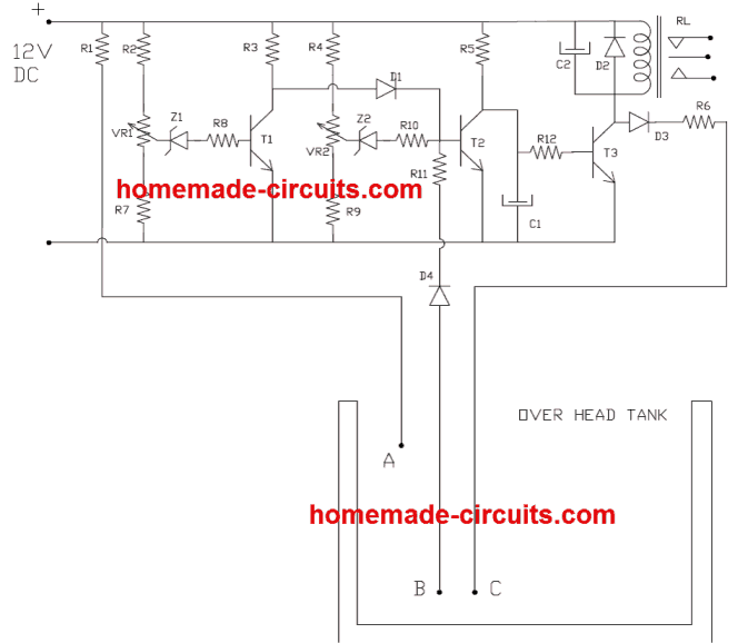
- PARTS LIST
- R1,R11 = 100K
- R2,R4,R7,R9,= 1.2K
- R3 -10KR5 = 4.7K
- R6 = 47K
- R8,R10 = 10E
- R12 = 100E
- C1 = 4.7uF/16V
- C2 = 220uF/25 V
- D1,D2,D3,D4 = 1N 4007
- T1,T2 = BC 547
- T3 = BC 639( try 187 )
- Z1,Z2 = Zener 6.3 V,VR1,
- VR2 = 10K PRESET
- RL = Relay 12V 200E, > 5 AMP CONT ( According to pump HP)
2) IC 555 Based Automatic water Level Controller Circuit
The next design incorporates the versatile work horse IC 555 for implementing the intended water level control function in rather very simple and yet effective manner.
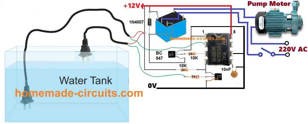
Referring to the above pictorial schematic, the IC 555 working can be understood with the following points:
We know that when the voltage at pin#2 of the IC 555 drops below 1/3rd Vcc, the output pin#3 is rendered high or active with the supply voltage.
We can also observe that pin#2 is held at the bottom of the tank to sense the lower threshold of the water level.
As long as the 2-pin plug remains submerged in water, the pin#2 is held at the Vcc supply level, which ensures that pin#3 stays low.
However as soon as the water drops below the lower 2-pin plug position, the Vcc from pin#2 disappears, causing a lower voltage than 1/3rd Vcc to generate at pin#2.
This instantly activates pin#3 of the IC switching ON the transistor relay driver stage.
The relay in turn switches ON the water pump motor which now begins filling the water tank.
Now as the water starts filing, after some moments the water again immerses the lower two pin plug, however this does not revert the IC 555 situation due to the internal hysteresis of the IC.
The water keeps climbing until it reaches the upper 2-pin plug, bridging water between its two pins.
This immediately switches ON the BC547 attached with pin#4 of the IC, and it grounds the pin#4 with the negative line.
When this happens the IC 555 is quickly reset causing pin#3 to goes low and consequently switching OFF the transistor relay driver and also the water pump.
The circuit now reverts to its original condition and waits for the water to reach the lower threshold to begin the cycle.
Calculations and formulas:
Threshold and Trigger Voltage Levels
The 555 timer uses two key voltage levels to control its operation in bistable mode:
- Trigger Voltage (Vtrigger):
The voltage at the trigger pin must be less than one-third of the supply voltage to set the output high.
Formula:Vtrigger < (1/3) * VCC - Threshold Voltage (Vthreshold):
The voltage at the threshold pin must exceed two-thirds of the supply voltage to reset the output low. - Formula:
Vthreshold > (2/3) * VCC
Where:
VCCis the supply voltage in volts.
SR Flip-Flop Behavior
The 555 timer operates internally like an SR (Set-Reset) flip-flop.
- If
Vtrigger < (1/3) * VCCandVthreshold < (2/3) * VCC, the output is SET (output = HIGH). - If
Vtrigger > (1/3) * VCCandVthreshold> (2/3) * VCC
This logic controls the water level controller's ON and OFF states.
Water Level Detection Voltage
The probes in the water tank form a resistive voltage divider. The voltage across the probes determines the input to the trigger or threshold pin:
Formula for Voltage at the probe (Vprobe):Vprobe = VCC * (R2 / (R1 + R2))
Where:
R1is the resistance above the water probe in ohms.R2is the resistance of the water between the probes in ohms.
Conditions:
- To SET the output high:
Vprobe < (1/3) * VCC - To RESET the output low:
Vprobe > (2/3) * VCC
Output Control
The output of the 555 timer controls a relay, which turns the pump ON or OFF.
- Output Voltage (Vout):
- When output is SET (high):
Vout = VCC - When output is RESET (low):
Vout= 0 - Relay Current (Irelay):
The current through the relay coil is calculated as:Irelay =Vout/ Rcoil
Where:
Rcoilis the resistance of the relay coil in ohms.
Debouncing and Noise Filtering
To prevent erratic switching caused by noise or rapid water-level changes, a capacitor and resistor are added to the input pins:
Debounce Time (Tdebounce):Tdebounce = Rdebounce * Cfilter
Where:
Rdebounceis the resistor in series with the capacitor in ohms.Cfilteris the capacitor used for filtering in farads.
Hysteresis for Stable Operation
Hysteresis prevents false triggering by introducing a gap between the SET and RESET points. A feedback resistor between the output and the trigger pin helps achieve this:
Feedback Voltage (Vfeedback):Vfeedback = Vout * (Rf / (Rf + Rinput))
Where:
Rfis the feedback resistor in ohms.Rinputis the resistor in series with the trigger pin in ohms.
3) Fluid Level Control Using IC 4093
In this circuit we employ a logic IC 4093. As we all know water (in it’s impure form) that we get in our homes through our house water supply system, has a low resistance to electrical energy.
In simple words, water conducts electricity albeit very minutely. Normally the resistance of tap water might be in the range of 100 K to 200 K.
This resistance value is quite enough for electronic for exploiting it for the project I have I have explained in this article that is for a simple water level controller circuit.
We have used four NAND Gates here for the required sensing, the whole operation may be understood with the below given points:
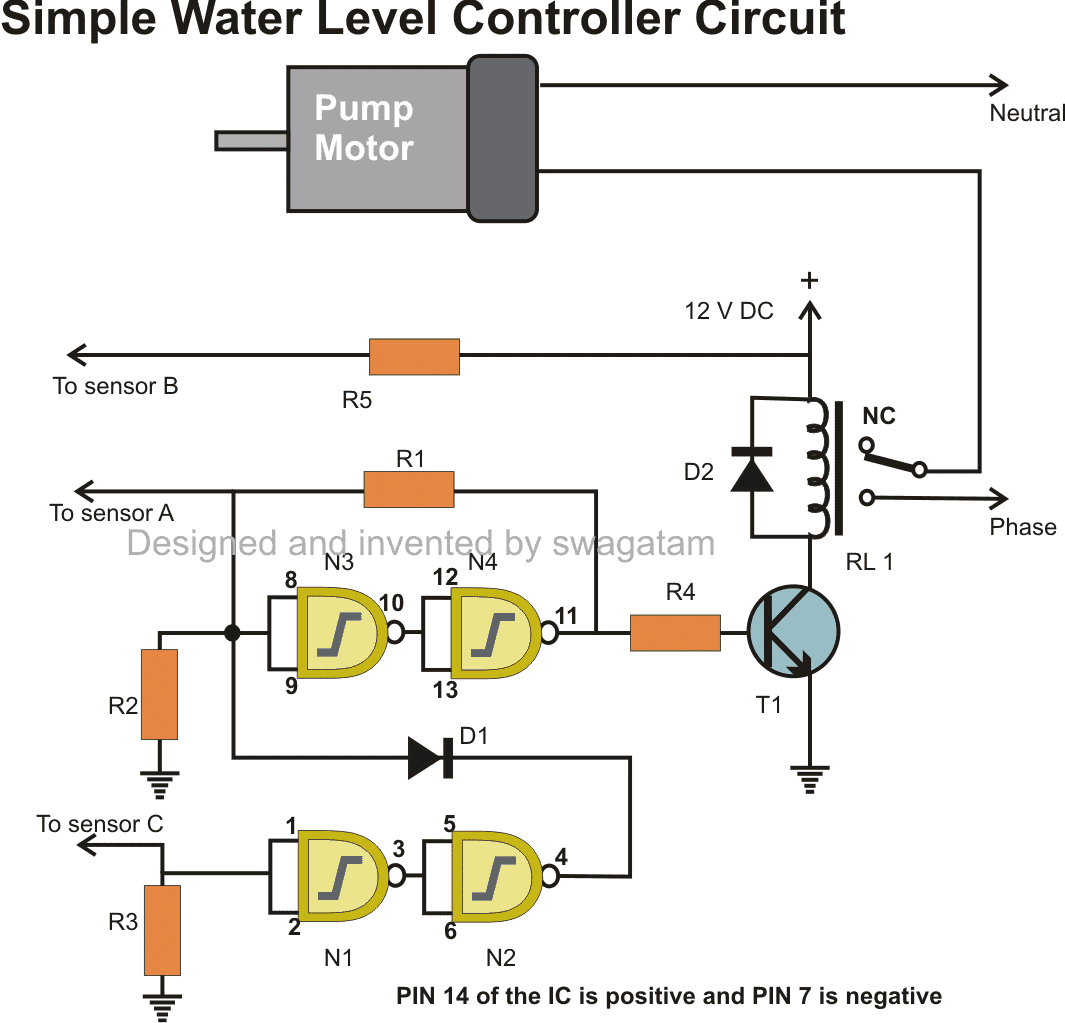
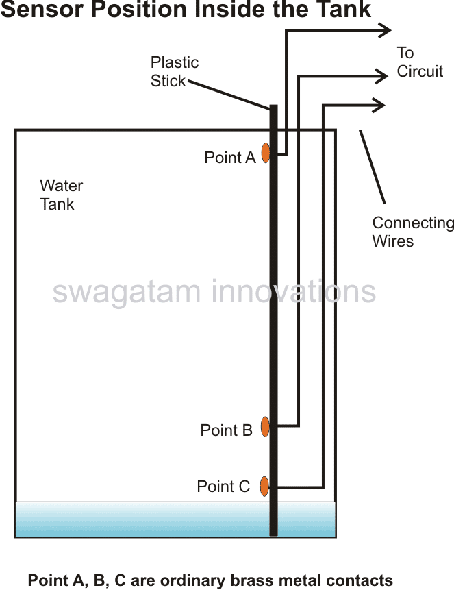
How the Sensors are Positioned
Referring to the above diagram, we see that point B which is at the positive potential is placed somewhere at the bottom section of the tank.
Point C is placed at the bottom of the tank, while point A is pinned at the top most section of the tank.
As long as water remains under point B, potentials at point A and point C remain at negative or ground level.
It also means that the inputs of the relevant NAND gates are also clamped at logic low levels because of the 2M2 resistors.
The outputs from N2 and N4 also remain at low logic, keeping the relay and motor switched OFF. Now suppose the water inside the tank starts filling and reaches point B, it connects point C and B, input of gate N1 becomes high making the otput of N2 also high.
However due to the presence of D1, the positive from the output of N2 does not make any difference to the preceding circuit.
Now when the water reaches point A, input of N3 becomes high and so does the output of N4.
N3 and N4 gets latched due to the feedback resistor across the output of N4 and input of N3. The high output from N4 switches ON the relay and the pump starts emptying the tank.
As the tank gets vacated, the position of water at some point of time goes below point A, however this does not affect N3 and N4 as they are latched, and the motor keeps running.
However once the water level reaches below point B, point C and the input of N1 reverts to logic low, output of N2 also becomes low.
Here the diode gets forward biased and pulls the input of N3 also to logic low, which in turn makes the output of N4 low, subsequently switching OFF the relay and the pump motor.
Parts List
- R1 = 100K,
- R2, R3 = 2M2,
- R4, R5= 1K,
- T1 = BC547,
- D1, D2 = 1N4148,
- RELAY = 12V, 400 OHMS,
- SPDT Switch
- N1, N2, N3, N4 = 4093
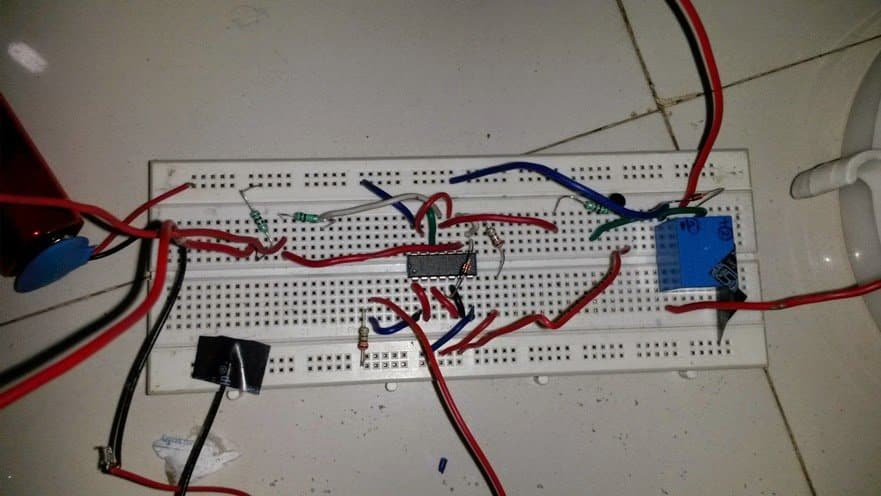
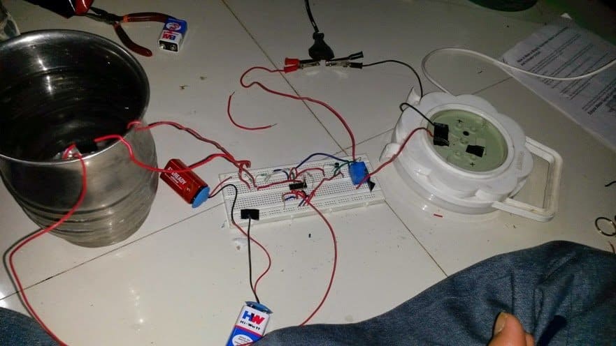
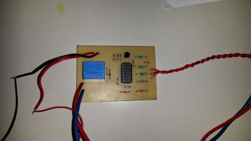
Prototype Images
The above discussed circuit was successfully built and tested by Mr. Ajay Dussa, the following images sent by Mr. Ajay confirm the procedures.
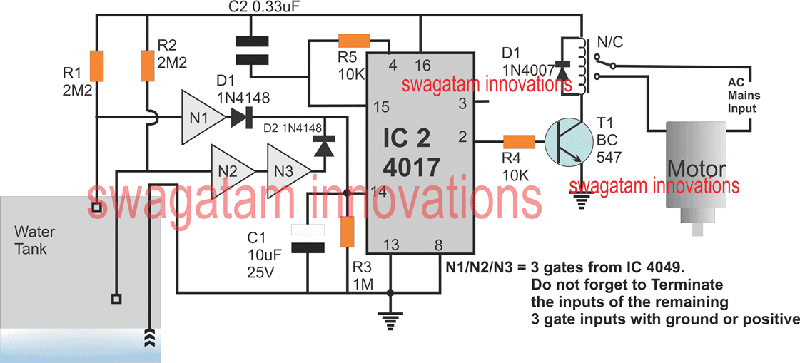
4) Automatic Water Level Controller Using IC 4017
The concept explained above can be also designed using the IC 4017 and a few NOT gates as shown below. The working idea of this 4rth circuit was requested by Mr. Ian Clarke
Here's the Circuit Requirement:
"I have just discovered this site with these circuits and wonder if you possibly can guide me….. I have a very similar necessity.
I want a circuit to avert a submersible bore pump (1100W) functioning dry, ie exhausting its water supply. I need the pump to shut off when the water level reaches approximately 1M above the pump intake, and start up again as soon as it reaches about 3M above the intake.
The pump body at earth potential would likely impart the typical reference. The probes and associated wiring to the surface area had been in place at those ranges.
Any assistance you can render would be much acknowledged. I will be able to put up circuits but hardly possess the understanding to figure the specific circuitry out. Many thanks in eager expectation."
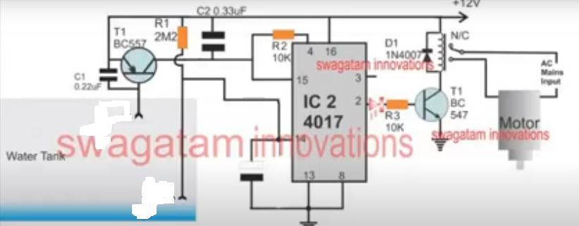
Video Clipping:
Please note that the circuit diagram shown in the following video is slightly different to the diagram shown above. However, the working concept is similar.
Circuit Operation
Let's assume the setup is exactly as shown in the above figure, In fact this circuit needs to be initiated in the existing position that's shown in the figure.
Here we can see three probes, one having common ground potential attached at the bottom of the tank and is always in contact with water.
The second probe is around 1 meter above the tank bottom level.
The uppermost probe above 3 meters above the bottom of the tank level.
In the shown position, both the probes are at the positive potentials via the respective 2M2 resistors, which renders the output of N3 positive, and the output of N1 negative.
Both these outputs are connected with pin#14 of the IC 4017 which is used as a sequential logic generator for this application.
However during first power switch ON the initial N3 positive output does not have any effect on the IC 4017 sequencing, because at switch ON the IC gets reset through C2 and the logic is unable to shift from its initial pin#3 of the IC.
Now let's imagine water beginning to fill the tank and reaching the first probe, and this causes the output of N3 to go negative, which again has no impact on the output of IC 4017.
As the water fills and finally reaches the uppermost probe, this causes the output of N1 to go positive. Now this impacts the IC 4017 which shifts its logic from pin#3 to pin#2.
Pin#2 being connected with a relay driver stage, activates it and subsequently activates the motor pump.
The motor pump now starts drawing water out of the tank and keeps emptying it until a time when the tank level begins receding and goes below the upper probe.
This reverts the output of N1 at zero, which does not impact the IC 4017 output, and the motor keeps running and emptying the tank, until finally the water goes below the lower probe.
When this happens, the N3 output turns positive, and this impacts the IC 4017 output which shifts from pin#2 to pin#4 where it is reset through pin#15 back to pin#3.
The motor stops here permanently... until the time when the water again starts filling the tank and its level yet again rises and reaches the uppermost level.
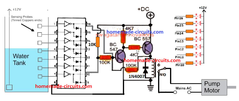
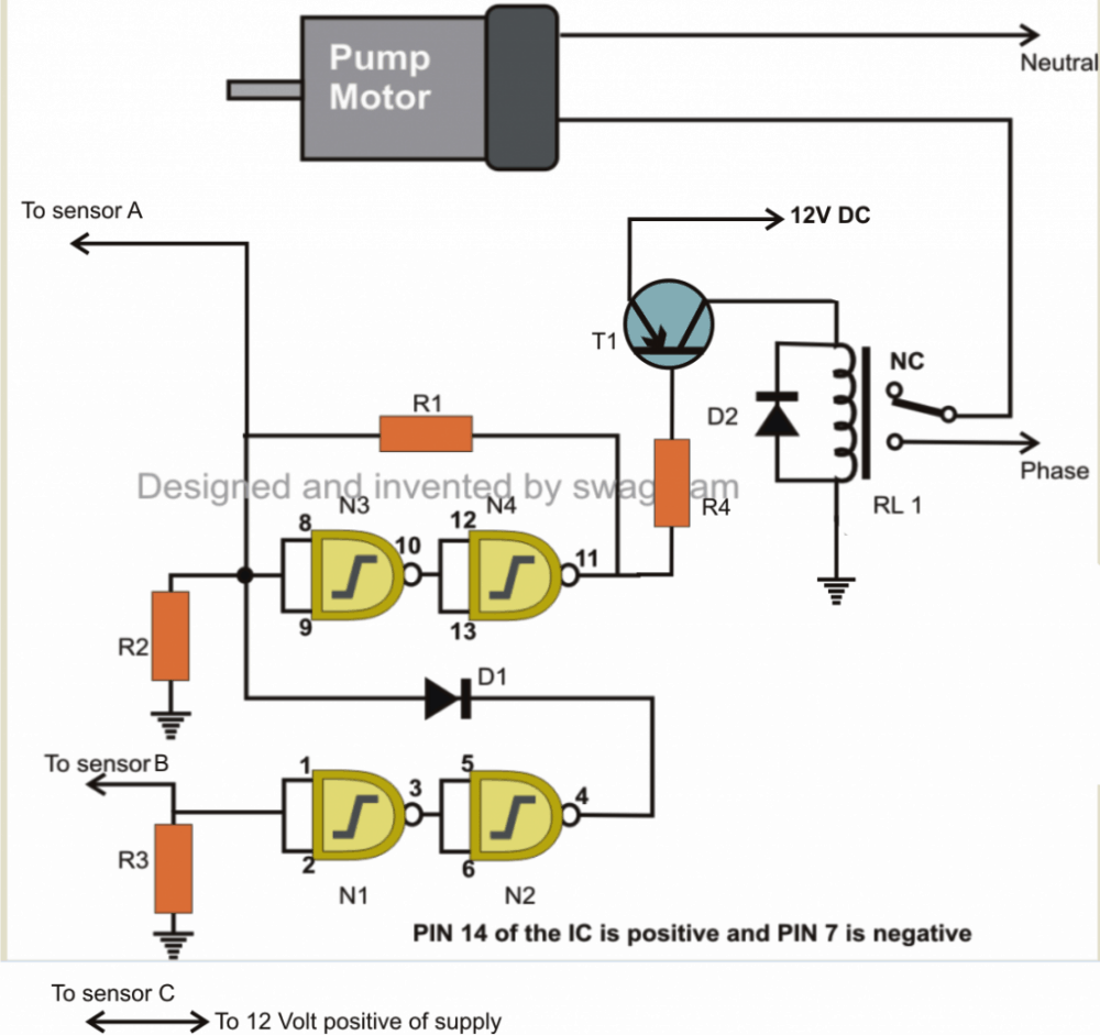
5) Water Level Controller Using IC 4049
Another simple water level controller circuit which is 5th in our list for controlling tank overflow can be built using a single IC 4049 and used for the intended purpose.
The circuit provided below performs a dual function, it includes an overhead water level control features and also indicates the different levels of water while the water fills the tank.
Circuit Diagram
How the Circuit Functions
As soon as the water reaches the uppermost level of the tank, the last sensor positioned at the relevant point triggers a relay which in turn switches the pump motor for initiating the required water evacuating action.
The circuit is as simple as it could be. Use of just one IC makes the entire configuration very easy to build, install and maintain.
The fact that impure water which happens to be the tap water that we receive in our homes offers a relatively low resistance to electricity has been effectively exploited for implementing the intended purpose.
Here a single CMOS IC 4049 has been employed for the necessary sensing and executing the control function.
Another interesting associated fact that’s associated with CMOS ICs has helped in making the present concept very easy to implement.
It is the high input resistance and sensitivity of the CMOS gates which actually makes the functioning completely straightforward and hassle free.
As shown in the above figure, we see that the six NOT gates inside the IC 4049 are arranged in line with their inputs directly introduced inside the tank for the required sensing of the water levels.
The ground or the negative terminal of the power supply is introduced right at the bottom of the tank, so that it becomes the first terminal to come in contact with water inside the tank.
It also means that the preceding sensors placed inside the tank, or rather the inputs of the NOT gates sequentially come in contact or bridges themselves with the negative potential as the water gradually rises inside the tank.
We know that NOT gates are simple potential or logic inverters, meaning their output produces exactly the opposite potential to the one that’s applied to their input.
Here it means as the negative potential from the water bottom comes in contact with the inputs of the NOT gates through the resistance offered by the water, the output of those relevant NOT gates sequentially start producing opposite response, that is their outputs start becoming logic high or become at the positive potential.
This action immediately lights up the LEDs at the outputs of the relevant gates, indicating the proportionate levels of the water inside the tank.
Another point that’s to be noted is, all the inputs of the gates are clamped to the positive supply through a high value resistance.
This is important so that the gates inputs are initially fixed at the high logic level and subsequently their outputs generate a logic low level keeping all the LEDs switched off when there’s no water present inside the tank.
The last gate which is responsible for initiating the motor pump has its input positioned right at the brim of the tank.
It means when the water reaches t the top of the tank and bridges the negative supply to this input, the gate output becomes positive and riggers the transistor T1, which in turn switches the power to the motor pump through the wired relay contacts.
The motor pump stats and begin evacuating or releasing the water from the tank to some other destination.
This helps the water tank from overfilling and spilling, the other relevant LEDs which monitors the level of the water as it climbs also provides important indication and information regarding the instantaneous levels of the rising water inside the tank.
Parts List
- R1 to R6 = 2M2,
- R7 to R12 = 1K,
- All LEDs = Red 5mm,
- D1 = 1N4148,
- Relay = 12 V, SPDT,
- T1 = BC547B
- N1 to N5 = IC 4049
All the sensor points are ordinary brass screw terminals fitted over a plastic stick at the required measured distance apart and connected to the circuit through flexible conducting insulated wires (14/36).
Upgrading the Relay Circuit
The above discussed circuit appears to have one serious drawback. Here the relay operation might continuously keep switching the motor ON/OFF as soon the water level reaches the overflowing threshold, and also immediately when the upper level reduces slightly below the topmost sensor point.
This action may not be desirable for any user.
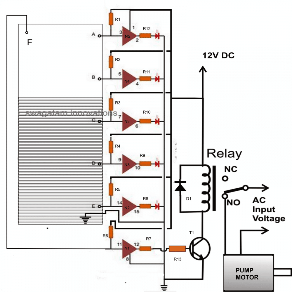
The drawback can be eliminated by upgrading the circuit with an SCR and transistor circuit as shown below:
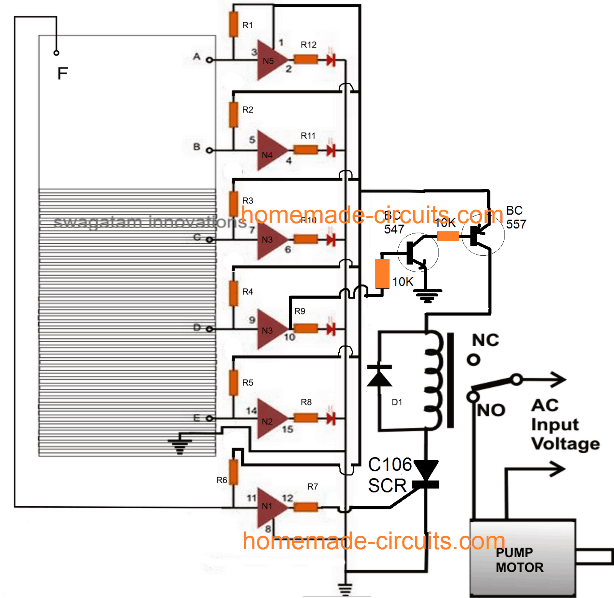
How it Works
The above intelligent modification ensures that the motor is switched ON as soon as the water level touches the point "F", and hereafter the motor keeps running and pumping the water out even while the water level drops below the point "F" .... until it finally reaches below the point "D".
Initially when the water level goes above the point "D" the transistors BC547 and BC557 are turned ON, however the relay is still inhibited from switching ON because the SCR is switched OFF during this time.
AS the tank fills and the water level rises upto the point "F" output of gate N1 turn positive latching ON the SCR, and subsequently the relay and the motor also switch ON.
The water pump begins pumping water out from the tank which results in emptying the tank gradually. The water level now drops below the point "F" switching OFF N1, but the SCR keeps conducting being in the latched situation.
The pump keeps running causing the water level to drop continuously until it reduces below the point "D".
This instantly switches OFF the BC547/BC557 network, depriving the positive supply to the relay, and eventually switching OFF the relay, the SCR and the pump motor. The circuit returns to its original situation.
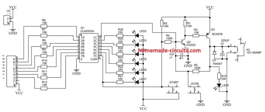
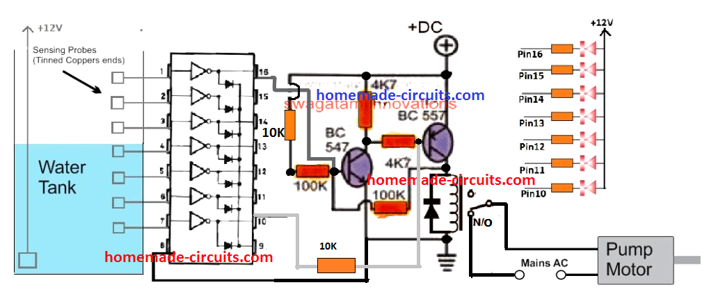
ULN2003 Water Level Controller Circuit
ULN2003 is a 7-step Darlington transistor array network inside a single IC chip. The Darlingtons are reasonably rated to handle current up to 500 mA and voltages up to 50 V.
The ULN2003 can be effectively used for making a full fledged automatic 7 stage water level controller with indicator as shown below:
How it Works
The transistor stage associated with the ULN2003 is basically a set reset circuit which is attached with the lowermost and the uppermost pins of the IC for the required set reset actions of the relay and the pump motor.
Assuming, the water level is below pin7 probe, the output pin10 remains deactivated, which in turn allows the positive supply to reach the base of the BC547 via the 10K resistor.
This immediately switches ON the PNP BC557, which instantly latches the two transistors via the 100K feedback across the collector of BC557 and the base of BC547.
The action also latches the relay switching ON the motor pump. The pump water starts filling the tank, and the water gradually climbs above the pin7 probe level.
Pin7 tries grounding the 10K biasing for the BC547 but this does not affect the relay switching, since the BC547/BC557 are latched through the 100K resistor.
As the water fills and climbs the tank, it finally reaches the uppermost pin1 probe level of the ULN2003.
Once this happens the corresponding pin16 goes low, and this grounds the feedback latch bias of the BC547 base, which in turn switches OFF the relay and the motor pump.
Making a Customized Water Level Controller
This customized ideal tank overflow controller circuit idea was proposed and requested to me by Mr. Bilal Inamdar.
The designed circuit attempts to enhance the above simple circuit into a more personalized form.
The circuit is exclusively designed and drawn by me.
Objective of the circuit
Well, simply, I want to add an acrylic sheet below my tank, which will contain tube lights. In short, acrylic ceiling.
The tank level can't be observed because of the sheet. This is also needed for the terrace tank of 1500 liters to observe level indoors without going outside.
How it will help
It will help in many scenarios, like to observe terrace tank level, to observe and operate overhead tank level, and to observe underground tank water level and operate the motor.
Also, it will save precious water from wasting due to overflow (go green). And release the tension caused by human error (forgetting to turn the pump on and filling the water; also turn off the motor).
Application area :-
Overhead tank
Size - height = 12" width = 36" length = 45"
the tank is used for drinking, washing & bath.
The tank is 7 foot above the flooring.
The tank is kept in the bathroom.
Material of the tank is plastic (or PVC or fiber whatever non conductive)
The tank have three connection
Inlet 1/2", outlet 1/2" and whirlpool (overflow) 1".
The water fills from inlet. The water comes from outlet for use. The overflow connection prevent water overflowing on the tank and channelized it to drainage.
The hole of outlet is lower and the overflow and inlet is higher on the tank (ref height)
Scenario :-
The tank probes and level
|_A probe (overflow)
|__ok level
|_D probe (Medium)
|__low level
|_B probe
|__very low level
|_C common probe
As per the scenario I will now explain how the circuit should work
Circuit notes:-
1) Input of the circuit from 6 volts AC/DC (for backup) to 12 volts AC/DC (for backup)
2) The circuit should mainly work on AC (my mains is 220-240vac) with the use of a transformer or adaptor; this will avoid probe rusting, which occurs due to positive and negative stuff.
3) The dc will drive from a 9-volt battery easily available or from an AAA or AAAA battery.
4) We have lots of power cuts, so please consider a backup DC solution.
5) The probes used are aluminum wire (6 mm).
6) The resistance of water changes as per location, so the circuit must be universal.
7) There must be a sound that is musical as well as different for very high and very low. It can go bad, so the next sound is preferable. A buzzer is not suitable for a big room of 2000 sq ft.
8) The reset switch must be a normal doorbell switch that can be put in an existing electric board.
9) There must be at least 6 led
Very high, very low, ok, low, mid, motor on/off. The mid must be considered for future expansions.
10) The circuit should indicate the led of the light gone when there is no AC current.
And switch to DC back. or add two LEDs for indication on AC and on battery.
Circuit functions.
1) Probe B: if the water goes below this, an indication led of very low must glow. The motor should start. The alarm should sound. The sound must be unique for a very low level.
2) If the reset switch is pressed, then the sound must go off; everything else remains the same (circuit armed, led glowing, motor).
3) If the water touches probe B, the sound must be killed automatically. The very low indication led turned off. The low indication led turned on nothing else.
4) Probe D: if the water touches probe The low indicator turns off. The OK level LED turns on.
5) Probe A—if the water touches this probe, then the motor turns off.
The OK level LED goes off, and the very high level LED glows.
The bell/speaker turns on with different tunes for very high. Also, if the reset button is pressed in this case, there must be no other effect than killing the sound.
Last but not least, the circuit diagram should be expandable to E, F, G etc. for very big tanks (like mine on a terrace)
One more thing, I'm not able to know how the midlevel should be indicated.
Too tired to write more sorry. Name of the project (just a suggestion): Perfect Water Tank Level Automation or Perfect Tank Water Level Controller.
Parts List
R1 = 10K,
R2 = 10M,
R3 = 10M,
R4 = 1K,
T1 = BC557,
Diode = 1N4148
Relay = 12 volt, contacts as per pump current rating.
All Nand gates are from IC 4093
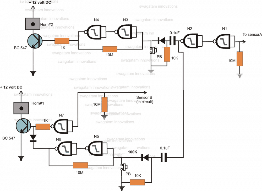
Circuit functioning of the above configuration
Assuming the water content to be at point A, the positive potential from point "C" in the tank reaches the input of N1 through water, making the output of N2 go high. This triggers N3, N4, transistor/relay and horn#2.
As the water comes down, below point "A" the gates N3, N4 maintain the situation due to the latching action (feedback from its output to input).
Therefore horn#2 remains switched ON.
However if the upper reset switch is pressed, the latch is reversed and maintained to negative, switching OFF the horn.
In the meantime, since point "B" is also at positive potential, keeps the output of the middle single gate low, keeping the relevant transistor/relay and horn#1 switched OFF.
The output of the lower two gates is high but has no effect on the transistor/relay and horn#1 because of the diode at the base of the transistor.
Now suppose, the level of the water falls below point "B", the positive from point"C" is inhibited and this point now goes logic low via the 10M resistor (correction required in the diagram which is showing 1M).
The output of the middle single gate immediately becomes high and switches ON the transistor/relay and horn#1.
This situation is maintained as long as the water threshold is below point B.
However horn#1 can be switched OFF by pressing the lower PB, which reverts the latch made from the lower couple of gates N5, N6. The output of the lower two gates becomes low, pulling the base of the transistor to ground via the diode.
The transistor relay switches OFF and hence horn#1.
The situation is maintained until the water level again rises above point B.
Parts List for the above circuit is given in the diagram.
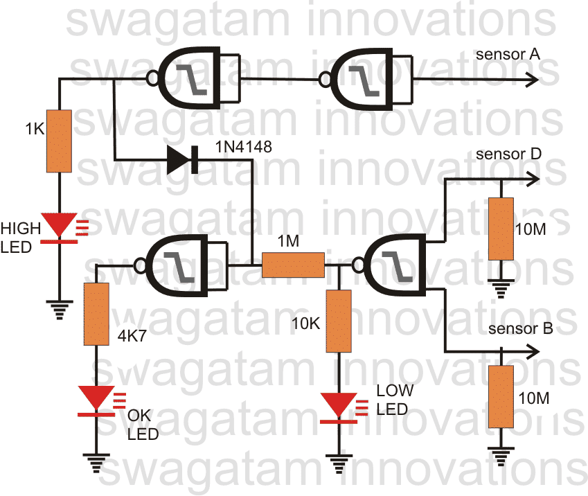
Circuit functioning of the above configuration
Assuming the water level to be at point A, the following things can be observed:
The relevant input pins of the gates are at high logic due to the positive from point "C" coming via the water.
This produces a logic low at the output of the upper right gate, which in turn makes the output of the upper left gate high, switching ON the LED (bright glow, showing the tank is full)
The input pins of the lower right gate is also high, which makes its output low and therefore the LED marked LOW is switched OFF.
However this would have made the lower left gate output high, switching ON the LED marked OK, but due to the diode 1N4148 it keeps its output low so that the "OK" LED remains OFF.
Now suppose the water level falls below point A, the upper two gates reverts their position switching OFF the LED marked HIGH.
No voltage flows through 1N4148 and so the lower left gate switches ON the LED marked "OK"
As the water falls below the point D, the OK LED still glows because the lower right gate still remains unaffected and continues with a low output.
However the moment water goes below point B, the lower right gate reverts its output because now both its inputs are at logic low.
This switches ON the LED marked LOW and switches OFF the LED marked OK.
Parts List for the above circuit is given in the diagram
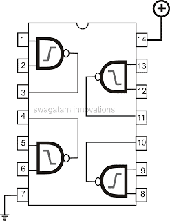
IC 4093 PIN-OUT Diagram
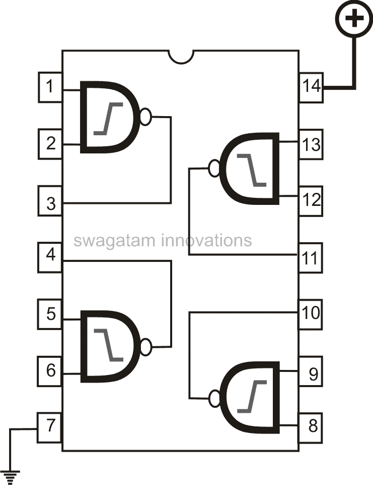
Note:
Please remember to ground the input pin of the remaining three gates which are not used.
In all three ICs would be required constituting 16 gates, only 13 will be used and 3 will remain unused, the above precaution must be followed with these unused gates.
All the relevant sensor points coming out from different circuits must be joined together and terminated to the appropriate tank sensor points.
Wrapping it up
This concludes our articles regarding the 5 best automatic water level controllers which can be customized for switching ON/OFF a pump motor automatically in response to the upper and lower water thresholds. If you have any other ideas or doubts please feel free to share them through the comment box below
With over 50,000 comments answered so far, this is the only electronics website dedicated to solving all your circuit-related problems. If you’re stuck on a circuit, please leave your question in the comment box, and I will try to solve it ASAP!
Good Evening Sir
Is it possible to connect TTL not gate in place of CMOS not gate will the functioning get disturbed.
Else how can I connect CMOS not gate to TTL nand gate there is a bc547 at each connection.
Please help me
Good Morning Dhananjay,
You can use TTL gates in place of CMOS gates, just make sure to regulate the IC supply voltage to DC 5V, that’s all, rest everything will work normally.
Respected Sir
Your ideas and circuits are quite good then why you are not making your own pcbs.?
Thank you for your suggestion Dhananjay,
Actually nowadays everything is available so cheaply on amazon, that too with highest quality. That is why manufacturing PCBs or kits is no longer a beneficial business for a person like me, unless I invest a large sum of money, which can be risky.
Respected Sir
I would like to say something which I had tried with your circuit design and diagram.
I had tried to run your water level controller circuit with few modifications.
I like to take your permission to run it on commercial way. It’s in initial stage at present, and working on it.
Since it was totally your indigenous ideas and design it’s my responsibility to ask you. I also request you to see the circuit diagram which I seem I had modified.
Please guide me with your views on this as well as circuit diagram attached with this mail.
Thank you Dhananjay,
No problem at all, you can build it for commercial purpose.
I checked your diagram roughly and it looked good to me.
Ideally you can connect a 10k resistor across the base/emitter of the PNP relay driver transistor, although it is not compulsory.
All the best to you!
Respected Sir
I want a suggestion for buffering the output of IC 4049 , how can I do that with transistor only otherwise I will have to add 4050 buffering IC for all the 4 output which I had used for control section.
Also can you suggest me a better idea for over under current control using optical isolators on 230 volt main line
Dhananjay, CMOS gates itself act like buffers, so adding additional buffer gates may not be required, unless there’s some specific reason.
For what application do you need the current control? is it for the pump motor?
Hi Swagatam,
Much appreciation for your effort and organized explanation. I want to make a circuit with two pick-up points, (A)1 low water level and another (B) full tank water level and a single LED. here are the scenarios.
1- when the tank is full ( at point B) LED is OFF and remains off until the water level drops below point (A), and then the LED is turned ON.
2- when filling the tank the LED should remain ON during the filling process until the water level reaches point B (Tank is full) then the LED should be OFF again.
I tried using different logic gates, but I think a latching action is needed since the logic changes in both scenarios.
Much appreciations.
Sami
Thank you so much Sami,
For accomplishing the mentioned application, I think you can try the circuit diagram which is shown in the video. Please see the diagram posted in the video and try implementing it. You can ignore and remove the transistor and the relay and use LEDs on pin#3 and pin#2 of the 4017 IC
Hello again, thanks so much for your quick response. I have the following questions:
1- I see where the relay is and understood your comment on switching the relay with an LED on pin # 2, but why do I need an LED or anything on pin #3?
2-I am not sure what N1,N2, and N3 are, I an guess these are logic gates. if so can you suggest the name of an IC
3- there are many variants of IC4017 can you please suggest an exact name?
4- the intention is to run the project on a 3v mercury battery is this going to be a problem?
once more, thanks for your kind support
Hi, I was actually referring to the diagram which is shown inside the video. Please play the video to see the diagram. The diagram inside the video does not have any N1, N2, N3 gates. You can use two LEDs just to get an alternating indications, if this is not necessary, a single LED will also be fine as per your specifications.
A 4017 IC can run on 3 V also I guess, if not then you might have to use a voltage doubler circuit to double the 3V to 6V for the 4017 IC.
You can use any 4017 variant, all should work….
thanks a lot, really appreciate your help. I will order the parts and do it. maybe I will come back with some questions, but really thanks a lot man 🙂
You are most welcome Sami, feel free to ask if you have any further questions.
Hej again.
I have been trying to do this but no luck. is there away where I can send images or a video?
thanks a lot
Hi, Please see the following diagram, did you try this circuit?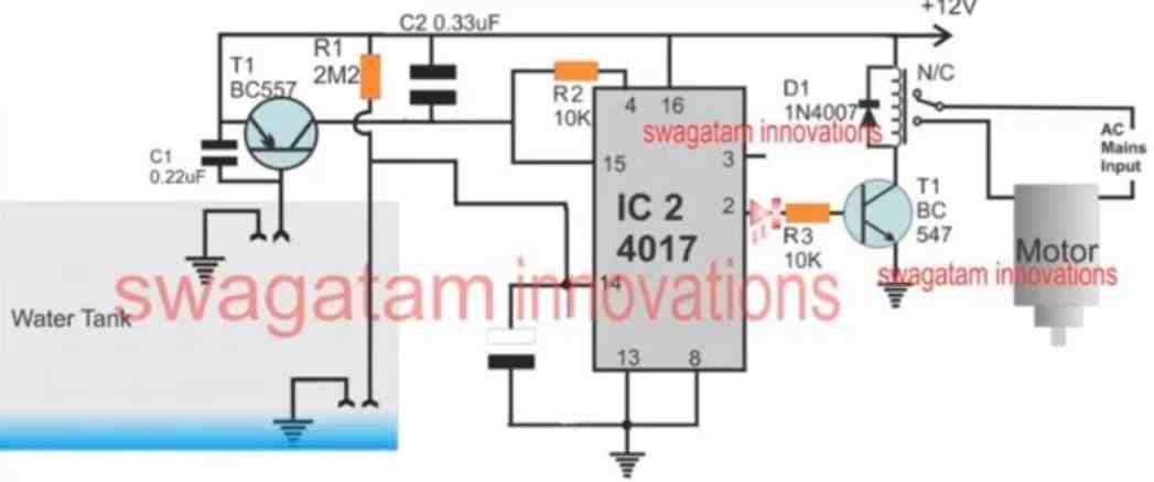
What problem are you getting?
Sending an image or a video might not help because I may not be able to troubleshoot by looking at the image or the video.
I followed this circuit and used 10 uf ceramic capacitor between pin 14 and the ground. it did not work. any suggestions ?
10uF is too large, try 1uF. Initially the lower pair of contacts must be immersed in water and then power to the circuit switched ON. Now the LED on pin#3 will illuminate. Then let’s assume the water level slowly goes below the lower contacts, this will cause the logic high to move from pin#3 to pin#2.
In this position the pin#2 LED illuminates, LED at pin#3 will shut off.
Now suppose the tank is being filled, the water rises above the lower contacts but the LED at pin#2 continues to remain illuminated.
The water level keeps rising until it reaches the upper contacts. Now the logic shifts back from pin#2 to pin#3, so now the pin#3 LED illuminates.
Now let’s assume the tank starts getting empty again and the water level drops below the upper contacts, but pin#3 LED continues to glow, until the water level drops below the lower contacts when the logic again shifts from pin#3 to pin#2…..and the cycle keeps repeating.
Thank you so much for your elaborate response, can I use 4700 pf capacitor instead? thanks
No problem Sami! 4700 pF looks to small, I think it should be at least 0.1uF or 0.22uF, otherwise the pin#14 could become unstable giving rise to erratic output results.
Hi Swagatam,
I would like to add an dry run protection with 1 minute waiting time, beeper, led and reset switch to the below circuit. So when the circuit detects a dry run for one minute means the relay should cut off and the beeper with led should turn on. A reset switch is required to turn off the beeper / led and to activate the relay again.
Am connecting the sensors with the float switchs. So, Does it require to change the value of R1, R2, R3 ?
And one doubt is, In this circuit you have used BC557 connected to relay and in another circuit which is in the above article, you have used BC547. May I know what makes the difference in this?
https://drive.google.com/file/d/1QP_bdswGkcHymp4Ea9fOk1fX25un5URD/view?usp=sharing
Hi Sriram,
The BC547 is the correct diagram, the BC557 might be for some other specific application.
In the BC547 circuit, the relay activates when the water reaches the top of the tank, so I am not sure how we can add a dry run protection in this circuit, because the relay will not activate the motor until the water reaches the brim of the tank.
R1, R2, R3 will not require any changes with float switches.
Hope I am posting this in the right place. I have been looking for a simple circuit to detect water level in a 130 meter deep water well. Our water table is dropping and I have no idea how deep the surface of water is. My access into the well is an 11 mm hole in the well head, not very big. Was hoping to find a circuit that would use two 18 gauge (SAE) SPT-2 wires, but preferably something smaller, like 20 gauge with some small lead or steel weights fastened to the end to keep the wire from coiling or curling as it goes down. 18 gauge SPT-2 wire will barely fit through the access hole without weights attached. Conductance between the bared wire tips when immersed in water could be the trigger. Another consideration is the wire has to be strong enough to not break under its own weight plus the weights. After the water level is sensed, I would pull the wire out and measure the length that was in the well.
It was suggested to me to use a volt-ohm meter to monitor resistance of the wire as it is lowered, and watch for a sudden change or listen for a continuity buzzer in the meter which would indicate the ends of both wires are now submerged. Maybe that is the easiest method to use, assuming the resistance change is measureable.
Thanks! Hope to hear some good news!
Your idea makes sense and will work. You can try that using a ohm meter to measure the resistance of the wire. When the wire ends touch the water, the resistance should drop to somewhere between 1 K and 4k7.
Hello Sir this circuit is great and is working well but I need same circuit for fuel( diesel) from over head tank to base tank .
Thank you Chris, Glad the circuit is working for you.
However, I am not sure how safe it would be to use a similar circuit for fuel tanks. Because the probes contain electricity and can be dangerous for fuel tanks
Good evening Mr.swagatam,
I request you to make a wireless water tank full alarm with remote calling bell available in the market since the wired one gets damaged due to exposure to sun and rodents. please do mention the modifications to be carried out. the range atleast must be 50ft (4 floors).The alarms available in the market are costly.
Good evening BLV Prasad,
I think you should try the following circuit and see if that helps:
https://www.homemade-circuits.com/ultrasonic-wireless-water-level-indicator-using-arduino-solar-powered/
Good evening Mr.swagatam,
I requested you guide me to convert the readily available remote wireless calling bell to a water tank full alarm. Being a retired electrical engineer, Iam not conversant with coding. Therefore, I request you to suggest me a the above alarm with arduino and microcontroller as a DIY. Thanks for the reply
Hello Mr. BLV Prasad,
I understand your problem, however I myself have not used the remote system which you have mentioned, and I do not know much about its working, so it will be difficult for me to help you in this regards.
Hello Sir
Using the IC circuit in the video 4017 I find that the circuit switches somewhat correctly on and off, but then it immediately turns back on after a fraction of a second, to about one second.
During the off period the BC557 Collector voltage goes to zero but then rises to about 1 volt and thus the output 3 of IC4017 goes to 12 Volts turning the output relay on again.
During the on period this output and the BC557 Collector voltages are at 12 Volts.
(I find that output pin 3 is actually the one which gives the correct output signal.)
I wouldn’t want to bother you with this but I’ve tried for days rebuilding it and replacing components, to no avail.
Do you have any suggestions on how to solve this?
(Would the other circuit using the Gates from IC4049 be more reliable?)
Many thanks for this and all the good kind work you’re doing!
Hello Hans,
I have tested the circuit thoroughly many number of times and I did not find such thing happening. You can see in the video that the circuit works perfectly.
If your BC557 is producing 1V at the collector without water touching its base then the transistor could be faulty.
Trying connecting a 4k7 or a 10K across the base/emitter of the BC557 parallel to C1, and check the response. The BC557 must be completely shut off as long as there’s no water touching its base. First check this without connecting the probes to the BC557 base.
The circuit in the video is tested and confirmed so I would recommend this circuit.
Hello sir, thank you very much for your prompt response.
Through a process of elimination it turned out that removing the capacitor on pin 14 solved the problem.
The controller is now installed and works reliably as intended.
It also appears that on power-up the output on pin 3 does not go erroneously high.
What was the intended purpose for this Capacitor?
Thank you very much for all your kind work.
OK no problem Hans!
The capacitor at pin#14 ensures that when the water goes below the lower threshold, pin#14 is triggered slowly, and not abruptly. This avoids bouncy effects and allows the output to sequence correctly.
The capacitor C2 at pin#15 ensures that whenever power is switched ON, the voltage enters through C2 and hits pin#15 to reset the output at pin#3….this ensures that the relay and the motors are always switched OFF whenever the circuit is initiated.
does this system work for a society having 10 overhead tanks, which has 2 nos 5hp motor pumps and manually operating for the water to get filled in all the tanks of the buildings
Yes they can be used but for society application I will recommend using float switch sensors.
Float Switch Controlled Water Level Controller Circuit
From your ULN2003 Water level control circuit, I have encountered more troubles. I’m not able to send a pic of my schematic on this format. I thought I saw a gmail address for you but can’t find it. My Darlington is overheating and burning out just pulling a 12vdc relay at 50 mA. Each channel is good for 500 mA . Can you give me a better route to send you my pic with details?
You can send the pics to homemadecircuits @ gmail .com
But I don’t think the images will help unless they are in schematic format.
There are no Darlington transistors in the circuit. Which transistor are you referring to?
In my previous email I had explained you everything about the working of the circuit, I hope you followed the explanation and understood correctly how the circuit is supposed to work.
Wow! Thanks for the quick response! Yes you are right about the water resistance. At my level intervals ( empty, 1/4, 1/2, 3/4, “re-fill”, Full ) I have the sensor as a tinned copper wire impaled thru plastic pipe and sealed PLUS I have the common “hot” with it about a 1/2” away. The 2004 IC works reliably from sensor inputs.
BTW, I altered your input with an AC version for anti-oxidation. I have 24 vac running to the sensor “tree” and they talk to PC817 Opto-isolators with a reverse bias 1n4148. I had to smooth out the 1/2 wave rectified pulse with a 22uF cap from the IC input to gnd. (No cap made horrible output chatter and a 10uF allowed occasional chatter for 1 second. ). An ohmmeter reading of the sensors shows 30k up to 110k resistance between probes but ohmmeter isn’t necessarily accurate for that reading)
The only DEVIATION from your schematic above is I used pin 16 and 15 outputs ( plus 1 and 2 inputs ) because I need to use the other outputs for more systems logic.
I really need for this thing to cycle between FULL and REFILL sensors and not cycle on and off when just the top sensor ( FULL) is wet or not.
The IC’s job is to just pull a SPDT 12vdc relay. After that I use relay logic for the system.
Thank you for your detailed explanation. Glad you could use the anti-oxidation process implemented for the probes. For the circuit to cycle the latch circuit needs to switch ON OFF in response to the output switching of the IC.
So it is important for the inputs to get a proper 12V from the water, and it is important for the IC outputs to produce perfect zero voltage whenever the inputs are subjected to 12V supply from the water.
Regarding the water level circuit using the ULN2003 IC and the 2 transistors: I did in fact create that circuit but it does not work as I thought. With both probes dry, the relay DOES energize, then as the lower probe becomes wet, it still stays energized as you stated. However, with the lower probe still immersed and the upper probe becomes wet, it “blinks off for 1/2 second then re-energizes. If I pull the upper probe out, the relay turns off and when I put it back in, it doesn’t blink, it just turns the relay back on.
What I was hoping for was to turn the relay on below the lower probe, have it stay on until the upper probe is immersed which turns off the relay, but then have it STAY OFF until the lower relay is NOT WET, to which it would re-energize the relay. Can you give me a circuit correction for this?
The latch circuit is actually a very accurate yet simple configuration. Basically, initially it is turned ON and latched with the current coming through the 10k resistor (when the 10k/100k junction is not held at zero voltage by pin#10, ….that is when pin#10 is not immersed in water)
Now, this latching can be broken simply by applying a 0V to the base of the BC547.
When the water reaches the upper limit of the tank, pin#1 is subjected to a positive supply through the water, which is supposed to cause pin#16 to become 0V.
So it is important to check whether pin#16 actually turns zero voltage or not when pin#1 is subjected to a 12V supply???
You can even manually connect a 0V or ground supply to the base of BC547 and you will find the latch instant breaks. However this latch will quickly get restored through the 10K supply unless the 10K/100K junction is held at zero volts which is implemented by the pin#10 while pin#7 is immersed in water.
So basically it is important to check whether the all the output pins are actually turning 0V or not when the input pins of the IC are immersed in water one after the other???
To make the BC547 more accurate you can connect its emitter to ground via a 1N4148 diode or a couple of 1N4148 diodes.
Also make sure the positive line inside the water is rather very close to the input pins of the IC, so that all the input pins are able to get proper 12V supply through the water, because the water resistance can be quite high if the 12V supply is held far away from the input pins of the IC.
Good afternoon my friend, Swagatam!
Question according to the scheme number 5 {Water Level Controller Using IC 4049}.
Is it possible to use only the upper and lower level sensor, removing all the others? Also I don’t need LED indication and what is the value of the resistor R13?
Hello Jorge,
yes you can keep the upper and lower probes and remove the rest, no problem. If you don’t need the LEDs you can short them with a wire link.
R13 can be a 10K resistor
Hi swagatham.
I need water level circuit.
1. Tank low, mid, high indication.
2. Sump/ground Tank low/ high indication.
3. CD-4001, 4093, 4017 IC.
4. Dry run indication.
5. Input sensor opto-coupler type.
6. Preferably low DC sensing voltage
Across sensor, when fully in water.
7. Some circuits measuring 0.5v DC across sensors, limiting electrolysis process very
Slow.
8. The sensors get cleaned once in 6 months.
9. CD 4081 & 555 ic combined circuit is good.
10. Can you release such type of circuits.
11. I want give the full finished assembled box to enquiries for installation.
12 we r going to use 0.5 or0.75 Sq.mm 3 core cable max 80mtrs length from motor to over head tank.
13. Any problem of using this length?.
Plz reply.
Thank you Shivkumar,
I actually have all these circuits, but they are posted in parts on different articles. You may have to join them together to make a single large circuit.
Joining all the circuits together will be a lot of work for me, and diagram can be too large to accommodate as a single diagram.
But if possible, I will try to do it and let you know.
The motor wire length will not be a problem.
Thank you for your reply. AC Sensing circuit is best. Plz post the circuit. The corrosion is fully avoided.
Hi swagatham, I am a regular visitor to homemade circuits and have successfully built some of your circuits, including the 555 circuit in this article. Thank you, great site. I have a problem with hard ground water with a very high mineral content, >2500 ppm. The probes soon are soon coated with crystallized minerals increasing the resistance and the circuit eventually fails. This is most prevalent on the bottom probes which are almost always submerged. The tank is on a high stand and it’s a mission to get up there and often clean the probe sensors. Is it possible to create a safe low voltage AC circuit (perhaps to only the probe sensors) that will perform the same function to automatically control the tank water level and mitigate the electrolysis effect? Maybe I missed it, but could not find such a solution. Looking forward to your response.
Thank you so much Reitz,
Glad you could successfully build some of my circuits.
Regarding the electrolysis of the water level controller probes, I think you can refer to the following post, which proposes a few remedies to solve this issue:
https://www.homemade-circuits.com/anti-corrosion-probes-for-water-level/
Actually, these ARE your circuits. All of them, and its really only the inputs to a ULN2004 and its outputs are very simple. I think you’ll recognise it in seconds if you see it. But this comment input won’t let me paste my pic in and I don’t know how you managed to get those other pics posted.
I’d really appreciate it if you could just give me a few seconds to ok my circuit.
I saw your email but the image is too small. Please send me a bigger image, but I can’t guarantee whether I will be able to figure out your circuit or not since the above article was created a long time ago and I seem to have forgotten the working of many of the circuits.
Hello Mr. Swagatam. I am making progress on my water pumping project. I have (2) submersible pumps in separate ponds that lift water 30’ into (2) 10,000 gal buried tanks. I have (2) shallow well pumps pulling from the buried tanks and filling a 6,000 gal upright silo tank which will gravity feed into another 6,000 gal cement plant process tank for filling cement trucks. We use about 30,000 gal water/day.
The silo has 5 sensor levels ( Full, begin fill, 3/4, 1/2, 1/4 and empty.) My sensors are made with 1/2” cpvc pipe with # 10 copper tinned probes impaled and soldered and sealed within to make an insulated, heat traced stand pipe for measuring tank gallonage.
I’ve used several of your schematics to make what I consider a reliable controller. I used the 12 vac probe voltage talking to opto-isolators which then talk to the uln2004 inputs.
The “full” input and the “begin fill” sensors are close together at the top of the tank and their 2004 outputs use your “cut in-cut out” circuit to pull the start stop relay.
The remaining sensor inputs directly pull 12vdc relays for other logic I have need for. Please review my schematic for accuracy as I am assembling my breadboard now. Thanks so much for your expertise and willingness to share your wisdom.
Hello Brad, I understand your issue, however I can troubleshoot only my own schematics which are published in the blog, It can be difficult for me to read and troubleshoot a circuit diagram from an external source, due to lack of time.
Hello sir . I like your blogs. Love from nepal. I have a problem. I want to make fully automatic water moter controller. The motor should be start when overhead tank level is low. And motor should Be stop 1: when the over head tank level is high. 2 when the undertank level is low. When water not reach overhead tank in certain time. The motor shoud be off and buzzer should be started and continue until do manual reset. Can you help me?
Thank you Pralhad, I think the first two objectives can be solved using the circuit which is shown in the video. The 3rd objective can make the design a little complex.
You can try implementing the circuit in the video and check whether it fulfills the first two objectives or not, then afterwards we can go for the 3rd objective.
Hi!
It fits not really in here but very close:-)
I have a water level sensor which gives me an output of 0-190ohm. It is connected to a gauge at 12V.
I want a little switching circuit which switches an alarm when the sensor reaches 180ohm. So when I am filling my tank I get a signal before it is overflowing.
Thanks,
Vespucci
Hi, you can try the following circuit for your application:
For setting up, put a 180 ohms across the sensing points, and adjust the preset so that the buzzer just starts buzzing.
Looks good. Will this work also with 12-13,8V?
VESPUCCI
Yes, it can work using upto 15V
Will the probs cause electrolysis in the tank water?
yes very mild electrolysis can happen.
Hello Swagatam and thank you for this blogpost.
I am trying to copy your water level controller circuit nr 4: Automatic water level controller using IC 4017.
Does the circuit work by using electrolyte capacitors(0.22 & 0.33 microFarad) instead of ceramic disk capacitors?
Thank you in advance.
Br Åsmund
Hello Asmund, yes you can use electrolytic capacitor for the 0.33uF, just make sure the positive terminal of the capacitor connects with the positive line of the supply
Thank you.
Also: In the movie there are three probes. However I can’t see the common ground probe in the diagram in the movie. Is it negligible in that circuit? Can you explain?
The diagram shown in the video is slightly different than the one shown in the article. Please follow the diagram which is shown in the video since it is much easy to build. The probes indicated with ground ends must be connected with the ground line of the circuit.
Hello good afternoon, I am a faithful follower of the site. I would like a level controller circuit. But also be anticorrosive .. Thank you very much.
Thank you for following this website, I’ll try to design a suitable anti-corrosive water level probes and let you know soon!
how to make zigbee 3 water level controller sir
As per the datasheet of ULN2003 pin 9 is VCC and PIN 8 is GND but in the circuit there is no VCC given to ULN2003 then how the circuit will work.
ULN2003 are Darlington transistor array, it is not an IC to depend on an operating Vcc supply. pin9 is not a Vcc pin, it is the common pinout of the freewheelinng internal diodes, check the datasheet again
Yes Sir, Thanks for reply.
Hi
when The circuit also opens an outlet valve when the level in the tank exceeds a particular level, and finally opens the inlet valve when the water in the tank falls below a particular level?
Hi, Am using power supply as 12v for entire circuit and snstead of ULN2003, Am using ULN2004. So do I have to connect any resistors for the input PINs 1-7?
And is there any transistor array with positive input and positive output? or any PNP transistor array?
hi, no resistances will be required at the input probes, just make sure to have individual positive supply close to the each probe end.
I searched but could not find any positive output array module.
Hi
Thank you for this information – next week I will buy components and assemble the system
Best regards
No problem, wish you all the best!
Hi
I am interest your solutions because I have to build system that will drain the water from the tank when it reaches a certain level
I have question about : 4) Automatic Water Level Controller Using IC 4017
There is a different electrical diagram on the website than in the movie
I’m interested in the solution from the film, can You send me the final electrical diagram with a list of components
Thank you in advance
Hi, here’s the diagram from the video clip:
All the parts are regular parts, you just have to write them down and show the shopkeeper to rpocure them
Since there are a few parts not labelled, I’ll provide the complete list below:
All resistors are 1/4 watt 5%
2M2 = 1no
1k = 1no
10k = 2no
transistor BC547, BC557 = 1 each
capacitor 0.22uF ceramic disc = 1no
capacitor 0.33uF ceramic disc = 1no
caapcitor 1uF/25V at pin14 of the IC = 1no
IC 4017 = 1no
diode 1N4007 = 1no
relay 12V. 400 ohm SPDT, = 1no
Hi Swagatam
I have a problem with 4) Automatic Water Level Controller Using IC 4017
You gave me diagram and elements
After starting the diode is on – relay coil is on
The probes are inactive (the cable ends are on the table)
I used a capacitor for a higher voltage – it should be 1uF 25V I have 1uF 63V
Is that problem?
Hi Martin, when power is switched ON, the logic high must start at pin#3, so pin#2 transistor/relay cannot be ON. Did you put the 0.33uF between the positive and the pin15 of the IC? This capacitor will always reset the IC to pin#3 during power switch ON
1uF/63V is OK, it is not a problem.
Hi swagtam, recently i saw a youtube where ac voltage is applied to a water level sensor to minimise the corrosion. The circuit is given below.
Kindly check the circuit and tell me whether it is viable. Coz i made and unsuccessful. I may be wrong in wiring. Pls reply
Chnadrashekhar, I have removed the link because external website links cannot be published. However, your circuit will not work because the capacitor will not allow th LEDs to illuminate correctly, and also because of the capacitors the current through water will be very less and not work.
Hi swagtam, pls look at the circuit below.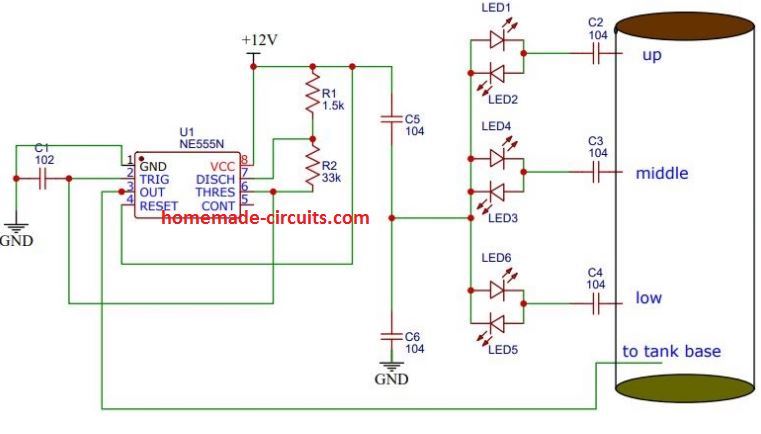
The circuit run smoothly. Now i want to add the S-R latch circuit for controlling Relay.
Pls let me know how to do this coz this is PWM based circuit i am afraid it will run.
Hi Chandrashekhar, in order to switch OFF the relay at high level, and switch ON at low level you will have to employ one of the circuits explained in the above article.
You can probably try this design”
Connect the upper robe with C2, and lower probe with C4
Thanks for reply. Now the problem is the probe is very sensitive and when i connect the long wire with the circuit the led glow slightly and when dip into the water the led gloaw fully. Pls resolve . And can i connect any S-R latch with this circuit coz it is high frequency AC. Pls do resolve with any simulation.
You said the circuit is working smoothly, so is it working smoothly with short wires? But since there’s no transistor involved here, so there’s no element which can amplify stray signal from the probes, so longer probes must have no effect. Please check your circuit and confirm whether it is working properly with short probes or not.
You can try any S-R if you how to connect it, you can rectify the high frequency with diode capacitor network for the S-R inputs
Yes Swagtam it working fine with short wire. But with longer wire, it get auto light without touching the water. Pls do resolve. Will i put a bridge rectifier with capacitor or a single diode enough?
Chandrashekhar, since there’s no amplifier stage so it is difficult to understand what is causing the LEDs to glow with large wires. You can try adding a 0.01uF or 0.1uF capacitor across pin5 and ground of the IC and see if that helps in any way, other than this I don’t see any other feasible option.
Hi Swayam. I created the circuit usi ga unna 2003 and bc547 n bc557. The problem is the relay switch as well as the LED connected to pin 16 of 2003 goes on and the relay does not turnoff. What to do I did all the schematic including 1uf connected to bc 547 base/emmiter. Pls let me know where did I wrong. Early response pls. Kindly send me ur email I’d pls
Hi Chandrashekhar, please check the latch circuit separately to verify if the circuit is actually working OK. To do this disconnect the IC pins from the latch circuit. Switch ON power to the latch circuit and make sure the relay does not operate by itself. Now, manually connect the point which was connected to pin 10 of the IC, with positive supply, only momentarily. The circuit must get latched now with relay clicking ON. To break the latch connect the base of BC547 to ground….this must switch OFF the relay….repeat the procedure 2..3 times to confirm the latch circuit is working OK…..
do this first and let me know.
Hi Swagtam. Thanks for early response.
As soon as the power on the circuit, the relay on itself. It does not require positive supply to 100k resistor which connected with bc547base. However if I disconnect between 10k and 100k resistor which is connected with bc 547, the circuit working fine as per desire. Mean circuit goes off when -ve to bc547base and goes on when +ve to 100k to bc547.
Pls tell me what to do
Hi Chandrashekhar, yes that means your circuit is OK….did you test the set up by pouring water in the tank???
Please connect the IC with the transistor and test by filling the tank fully with water and then slowly empty the water
Hi Swagtam need to chat with u and showing my problem. Pls share the chart option. BTW whenever base of bc547connect to pin16 of ic the light connected with ic got light up wheather the pin1 connected to +12v or not. Pls have a solution
Hi Chandrashekhar, the circuit will operate correctly only when you pour water in the tank with the probes immersed, otherwise it will not work. Please remove the LEDs from pin10 and pin16 it might interfere with the operations.
When water touches pin7 to pin1, all the output pins from pin10 to pin16 will turn zero volt, and the transistor relay circuit will be switched OFF.
When water is drained out, pin1 will be removed from water contact, removing zero from pin16, but still the relay will be off because pin10 is still zero.
when water drops below pin7…the 0V will be removed from pin10, and now the transistor circuit will latch along with the relay and switch ON the pump
Hi sir, 80℅ problem solved. Now when the water touched the pin 1 the relay double tick and remain on and again when water receded from pin 1 the relay off. But from pin 7 to 2 all r ok. I have connected 1uf capacitor at base-emittor of bc547. Pls chk
Hi chandrashekhar, When water touches pin1, pin16 will turn zero volt so how will the relay click…
please switch ON the circuit after filling the water tank fully….and then slowly the drain the tank and check the response
Hi Swagtam. As per ur reco, I switched on the circuit after filling the tank. Now the relay is on. If water got drained the relay switched of as soon as pin 1 get untouched. It means the motor run indefinitely but on drainage the motor stop. It will not help me
Hi Chandrashekhar, how can that happen, it means either your IC faulty or the IC inputs are not getting the positive supply from the water.
When the input pins come in contact with water, the corresponding output pins must turn zero volt.
When water comes in contact with all the input pins, all the output pins turn zero volt, in this situation how will the BC547 transistor base get the trigger voltage? And how will the relay switch ON?
Please check your circuit accordingly
Hi Swagtam, thanks for replying all my queries. I have build the circuit and the circuit run smoothly. I replaced relay with a 30Amp 12v relay and connected a led with 330ohm resistor across relay. Now my problem is whenever the water touched pin 1 of ic 2003 the relay stopped and my 0.5hp motor stopped. Again after some time when water receed the relay chattered and this burned the relay. I already attached a 220uf cap across relay. Pls help me. Pls view https://drive.google.com/file/d/1ED2EF1QqscRz2EJLRnPXE0wbLdpeqjYq/view?usp=drivesdk. Any other method beside uln2003 to stop the relay when water full?
Hi chadrashekhar, you should always check the circuit without a load, and once finalized then you can attach a real load. To stop chattering add a 10uF/25V capacitor right across base emitter of BC557
however, since the circuit is supposed to latch then, it should never chatter.
did you check whether the IC outputs are getting zero volt or not when water touches the corresponding input probes…this is very important.
The zero volt must be sharply created, and this will only happen when the input pins get a proper positive potential from the water.
You can manually touch the positive to the respective inputs of the IC to simulate water filling and check the response of the circuit. Make sure to do this through a 1K resistor in series with the positive
Hi Swagtam, thanks for earlier replies. I created the circuit based on your recommendation. have a look the circuit pls.
The circuit run smoothly when water lower the pin 7 of ic the motor run automatically and when water touched at pin 1 the Relay stop and the motor also stopped. Now when the water started decreasing below pin1 the relay start chattering and this caused the relay burned. i connected a 0.5HP motor on it. My relay is 30AMP 12V. I connected 220uf/16v cap and a led with 330E resister across the relay. pls help me. and is there any solution to stop the relay without ULN2003, I mean any transistor biasing . pls look my circuit diagram where I was wrong. Also when the water touched the PIN 1 of IC the relay stopped but the voltage across relay is 6-7Volt.
Hi Chandrashekhar, remember I advised you not to connect LED to pin7 and pin10, please remove LED from pin7.
your circuit is OK…an instead of BC557 please connect 2N2907, because 30 amp relay is heavy for BC557.
ans please do not connect any motor until the circuit is fully tested.
it is a very straightforward design and should work without problems if the IC is correctly optimized
The circuit run smoothly when water lower the pin 7 of ic the motor run automatically and when water touched at pin 1 the Relay stop and the motor also stopped. Now when the water started decreasing below pin1 the relay start chattering and this caused the relay burned. i connected a 0.5HP motor on it. My relay is 30AMP 12V. I connected 220uf/16v cap and a led with 330E resister across the relay. pls help me. and is there any solution to stop the relay without ULN2003, I mean any transistor biasing . pls look my circuit diagram where I was wrong. Also when the water touched the PIN 1 of IC the relay stopped but the voltage across relay is 6-7Volt. https://drive.google.com/file/d/1zDYzlPPbryAjDvqDwupnkXoTlIgmTT2r/view?usp=sharing
when water goes below pin1, pin7 will be still under water, and therefore pin10 will be be zero volt then how will the BC547 base get the power to operate the relay?
please simulate it manually as explained in the previous comment.
Hi Swagtam. Now i have connected another bc547 with 10k at its base and dip other part of 10k into upper part of tank. And collector to the base of bc547 to 1st bc547 latch. Emitter to ground. In this way i stop the relay. I removed pin 16 as input to base of 547. Now solved but the sensing is too high. What to do now?
Hi Chandrashekhar, that may not be required, you just need to bring the positive terminal at 1 inch distance to probe1 and probe7 individually…this will do the job nicely.
Hi Swagtam, now I have discovered that the when I disconnect the pin 16 which connected to base of bc547 the circuit seems fine. The relay start when pin 10 got activated. But on connect pin 16 to the base the relay does not goes off. On connection of ground to base of bc547 the relay goes off.
Sir…. I’m electrical diploma student…..I make a project on cooler…..so I want a some idea for my project… Please guide me………
Sir muze mere project guide ne Limit switch ke upar circuit banane lagata tha but main thing is muze exact pata hi nahi hai ki limit switch work kese krta hai ….. Or use cooler me kese use Kiya Jaye ga…………. .?
Jayant, limit switches are those switches which either switch ON or switch OFF its contacts when its lever like arm is pressed. You can see an example of a limit switch operated circuit in this article:
https://www.homemade-circuits.com/simple-gate-openclose-controller-circuit/
Sir ,
Can u please let me know, which ic it is. I hot it on a water pump controller circuits from China.
IC GZF1014
Shantanu, I tried to find its datasheet but it seems there’s no reference about this IC anywhere online.
Can anyone tell me advantage & disadvantage of water level indicator ic 4093 it’s urgent as I need it for project plz help
The disadvantage is the probes placements which are not in the standard form. The 4017 circuit shown in the video is the best one according to me
Swagatam, Thanks for your reply regarding the uln2003 circuit, but as per your circuit I am not getting my desired result. In your circuit the relay switches on when pin 10 of the ic 2003 is low or in deactivated state, whereas I want the relay to switch on when pin 10 is high or in activated state as I am using pin 7 as a sensor for my ground level sump, please help I am stuck at this problem. The functioning of pin 16 to switch off when tank is full is Ok with me and suits my requirement.
Sanjay, the shown circuit should fulfill your requirement as desired.
As per your requirement when the sump tank is full it must switch ON the relay and the motor. The water is now pulled up into the OH tank which starts filling, when the OH water level is full the relay and the motor is switched OFF, I hope I understood it correctly.
In the shown circuit the pin7 sensor will go to the tank full level or the brim of the sump tank, pin1 will go to the full level or the brim of the OH tank.
When the sump tank is full, it will switch ON the motor, when the OH tank is full it will switch OFF the motor.
Ok I think I got the issue, in the circuit pin10 response must be reversed for fulfilling your requirement, I’ll do it soon and provide you the updated diagram…
Please try this diagram:
Swagatam, regarding the uln2003 circuit, I am unable to fulfil my requirements which are as follows:-1.pin 7 of ic uln2003 will go to the sensor in the sump which should switch on the relay with output from pin 10. 2.pin 16 should switch off the same relay and the pump for the OH tank. Please show the required modification. If you use SCR will 2P4M Scr work?
Sanjay, the circuit shown in the above article will do exactly that, just make sure to place the pair of contacts across the two tanks appropriately.
Hi.
thanks for the ideas. in the case of the 2:nd circui with 555 timer, wich relay is used? thanks
It’s a 12V relay, the details can be found at the bottom of this article:
https://www.homemade-circuits.com/how-a-relay-works-in-circuits-how-to-connect-it/
Hi
Thanks for replying.
I’m learning a lot from you.
But I want to make waterlevel controller which can remember its previous state even after power cut without using battery.
If possible Could you please help me in making this.
Thanks Avi, please see the diagram under this heading: Mains Failure Backup and Memory for the Flip Flp Circuit
in this article
https://www.homemade-circuits.com/build-these-simple-flip-flop-circuits/
check how the pin#14 is configured with a 2200uF capacitor, you can do the same for the IC 555 also, it might just work
Hi
The above ic555 water level controller circuit is very simple and cost effective to make, however i have a doubt. In practical conditions if there is power cut when motor is on. Will it remember it’s previous state and again start the motor by itself.
Hi, you will have to employ a small battery backup, otherwise it will fail to remember its earlier position
Good day Sir,
i am using a water level controller circuit in my dog’s drinking bowl for almost a week by now and its just working great and i just really love watching it working, as the dog consumed the water it will just automatically fill up to the preset level. i am using a very small submersible aquarium water fountain motor, i put it inside a 25 liters bucket with lid in a rack just above the dog’s bowl the water runs thru an aquarium air hose which has a very small hole just enough to fill the bowl slowly and it doesn’t bother the dog while he’s drinking
my concern is that, is there any effect on my dog’s health in the long run with this set up? i didn’t see any unusual reaction with my dog while drinking.
i am using a mineral water ( no chlorine added ) with a small additional amount of tap water because i don’t know why my probe doesn’t conduct with pure mineral water alone.
thanks,
amor
Hi Amor, a Dog’s gut is much stronger and immune compared to humans, so I don’t think it will affect the animal in any manner, still to be fully sure you can confirm it with a specialist or a vet.
Design and Implement a circuit that could give the status of 4 filling tanks when any two of the tanks need filling. The indication shall be implemented using a LED.
Dear Sir,
Thank you very much sir, so kind of you. Looking forward for your update sir.
Best Regards
PG Ragavandir
You are most welcome!
Dear Sir,
Circuit is working nicely sir with a slight change, thanks for your support so kind of you.
Will be in touch with your permission sir.
Thanks & Best Regards
PG Ragavandir
That's great Ragavan, I am glad it's working for you! keep up the good work.
Dear Sir,
Greeting for the day, sir I'm looking for a circuit which Pump Motor get 'ON' & 'OFF'by using Remote or by mobile message for around 10 Km surrounding, it will be used for Farmers for there land (which they can be bit tension free). if possible can you help me for supporting them please.
Thanks & Best Regards
PG Ragavandir
Dear Ragavan,
I'll try to upadte the article soon in my website.
Dear sir,
Eagerly waiting for your reply.
Thanks & Best Regards
PG Ragavandir
Dear Ragavan, I have already replied, please see the previous comment
Dear sir,
Thanks for the response & support, sir I tried what you told but same problem again, now I came to know that after the motor getting 'ON' automatically after 1 hour 30 min because of the BATTERY, If we change new battery to the circuit immediately, again the circuit is working normally.
Sir in this case whether I can use transformer? if so please tell me how to connect transformer and which one? If you say I will send photo sir. Eagerly waiting for your reply.
Thanks & Best Regards
PG Ragavandir
Dear Ragavan, battery is actually not recommended since it can discharge and cause instability, a transformer power supply is ideally recommended for this circuit.
alternatively you can buy a 12V/1amp AC/DC adapter from the market and simply connect its (+)(-) wires at the points where you had previously connected the battery supply, that's all you need to do for the wiring
Dear Sir,
I'm happy for your continuous support, will test and come up with a good result soon sir. thank you very much.
Thanks & Best Regards
PG Ragavandir
You are welcome Ragavan, wish you all the best!!
Customizing for 1 Hp Water Pump Motor
Dear Sir,
Thanks for sharing this valuable information, Hats-off to you.
As per this circuit it is working very well, but when it is connected to Half or One HP motor, when it goes beyond 'B' motor getting ON and when it touch 'A' motor is getting OFF, and then now it is in standby for 1 hour and 30 minis motor is in OFF condition only, but same all three points (A,B,C) are immersed, after 1 hour and 30 minis motor is switched ON automatically if it is even all three are immersed and it is not getting switched off till we OFF manually, can you please help how to rectifies this issue. I'm using every thing as you told.
Thanks & Best Regards
PG Ragavandir
Thank you Raghavan, I appreciate your enthusiasm,
check the circuit again by replacing the motor with a 100 watt bulb, if it works normally then the problem could be in the relay, or due to instability.
Make sure the relay contacts are rated to handle at least 30 amp current and for this the BC547 driver transistor will need to be upgraded to 2N2222, and also connect 0.22uF capacitors in parallel with R2, R3 and across base/emitter of T1.
also if the water is turbulent in the tank, then the sensors might fail to detect the connections across the terminals….to prevent this you can immerse the contacts within a plastic pipe so that the water column inside the pipe provides stable water levels for the sensing.
CANE I USE A RELAY JOX-15F(90)
My apologies for not replying as i was not sure if the question was directed at me. A JQX – 15F (90) works well but I prefer the smaller footprint such as RT424006 but they are only rated at 8amps whereas the JQX is rated up to 40 amps depending on the one you get. Regards, Mike.
thanks Mike, you have been very helpful!!
Using BC337 and BC327 transistors and three relays
My water project is up and running thanks to your circuits. Sensing probes are always a problem and I used a simple method in the pharmaceutical industry since 1979. Simply use 2mm 316 stainless welding rod forced through a 1.5mm drilled hole in a good quality plastic fitting. It never rusts and is small enough not to be affected by too much water motion. In addition, your circuit can be driven by 3 or 4 volts, so , I used second hand 5 volt cell phone chargers to power them. These are obtainable locally for ZAR 10. These give plenty power to drive 6 volt relays and of course they have been designed almost bullet proof and are compact. I have the project on facebook (Mike Ellis Kloof) and made the project public, so you can see it if you want. But essentially I am collecting water off our roof and ditching the first 400 litres as a first flush. As soon as the tank is filled a 0.55Kw pump is switched on and that sensing circuit also powers another relay to switch on a second sensing circuit on the 2×5000 litre main tanks. When the main tanks are full their sensor redirects the water to the ground at the back of our property. The main tank feed is then used via a pressure controlled pump to feed the house. This pump is also protected by one of your circuits to switch off in the event the tanks get empty. Thank you once more for your circuit which I have acknowledged on Face Book. The circuit I used for 40 years at my work , used BC337 and BC327 transistors and three relays. It was also bullet proof, but the cost of the relays made it expedient to use your circuit. Once more thank you for your effort to make life easier for us. Kind regards, Mike.
Thanks so much Mike, that's amazing, you have turned my designs into reality.
I appreciate your efforts a lot, in future if you have any queries regarding any new circuit-idea please feel free to drop a comment, I'll be always there to help you.
cheers!!
Dear Mr. Swatagam. Many thanks for your well designed circuits. I wish to pump water in a similar fashion from a tank collecting rain water. Will the high resistivity of the water be too high for this circuit to work and if so is there a way of amplifying the signal to make it work? Our rain water has a conductivity of 5 to 6 microsiemens/ cm compared with our municipal supply at 200-300 microsiemens per cm. I have to pump the rain water from a 750 litre collection tank near the house to a position above and behind the house to fill two 5000 litre tanks. Thanking you, Mike Ellis. Durban. South Africa.
Thanks Mike, Rain water will also have some impurity in it since it has to go through many pollutants in the atmosphere, and this will be enough for conducting electricity to some extent. But if there's a lot of movement in the water then the sensitivity of the probes can get affected…to remedy this you can add a pipe enclosure around the probes, meaning use a long pipe inside the tank, and keep the probes inside this pipe such that the water column inside the pipe can be used for the conduction and detection.
Sir, can i use 2m ohm resistor instead of 2M2 or any other suitable number. kindly help
Gowhar, the value is not critical it just has to be much higher than the resistance of water
2M will do
Is it necessary to change resistance or transistor value if i use ic4017? Another thing u have not provided pcb layout, is there any software to make layout?
the resistance wattage can be 1/4 watt but the configuration will change entirely.
for the PCB you can contact any qualified PCB designer, he will do it for you.
Sir can i use ic 4017 here? Another thing i did not understand why u have not used 1n4007 as a free wheel diode?
Kaushik,
you can use IC 4017 or any other suitable configuration for implementing the idea….you can use 1N4007 diode for the relay coil if the relay coil resistance is much lower or if the relay is rated to handle more than 20 amps
Hi,
very helpfull post!
Can you help me telling me how to deal with the circuit running reversing the relay?
I need it to run at the NC position because I have a Preassure sensor to activate the pump and I want to disable the system when no water is at the bottom level sensor opening it. When the both sensors are powered then the relay become open instead of closed. Thanks!!!!
Hi, thanks, if you want to reverse the relay and the motor operations, you just need to apply the indicated N/O phase supply to the N/C contact of the relay
Thanks foir your reply!
I did that, but I guess I need to explain myself better.
The system needs to operate the opposite way you planned, I need to power the relay coil when NO water is in the tank but turn it off when water reaches the top sensor so the pump get in phase. Then gates get latched (relay power is still off) until water reaches the bottom sensor where reley coil is powered and pump circuit opens. I just not want to get the relay powered all the time because almost 99,9% of the time the UGT tank would be filled. I think that its better to activate to shut the system of in case of no water is present.
Thanks again!!!!
If you don't' the relay to be powerd all the time then you can try replacing the BC547 with a BC557 and connect the relay/diode assembly across its collector and negative supply…the emitter will go to the positive supply….rest everything can remain exactly as given in the diagram