In this article I have explained an alternator power booster circuit which was unveiled by one of the keen followers of this blog, Mr Michael Mbamobi. I have explained more about the details.
Technical Specifications
There is this circuit I want to show you. I want to show you the circuit through Homemade Circuit or Brighthub.
I didn't see how I can upload picture there. Please direct me I can sent this through Homemade Circuit. Anyway I uploaded the picture here! see the circuit and find out what these our Nigerian Guys are up to. I only hear about this type of device here in Nigeria.
I bought it and disassembled it. With your ability as Engr. Swagatam Majumdar, you can build a better device that can perform this same thing without depending on their own construction.
The folks call this an alternator power booster! It enables small gensets support loads bigger than their coils and feel alright with it without yearning!
I disassembled it carefully because D1, R1, R2, C2 and Q1 are obscured inside a glue like paste.
AC IN is from a small 650VA Generating set which is normally incapable of powering the connected loads.
The diode polarity and the value is not certain but this is its place in the circuit. It got broken while dismantling the glued circuit.
Q1 couldn't be traced either because the print was scraped of by the manufacture.Only its pin#1 and pin#3 responded to the DMM, it read zero like a dead diode, pin#2 does not read with any other pin at all. Pin#4 which is the tab is also unconnected.....just cannot figure out the device or its specs.
The diode D1 is blue in color, small glass type.
Solving the Circuit Request
Dear Michael,
It looks like an AC voltage booster circuit to me. Q1 is probably a power triac, the diode might be a diac DB-3, I am assuming this since it's small glass type and blue in color.
I would be addressing this circuit in my blog very soon....kindly stay tuned for the updates in my blog.
Thanks and Regards.
Circuit Explanation
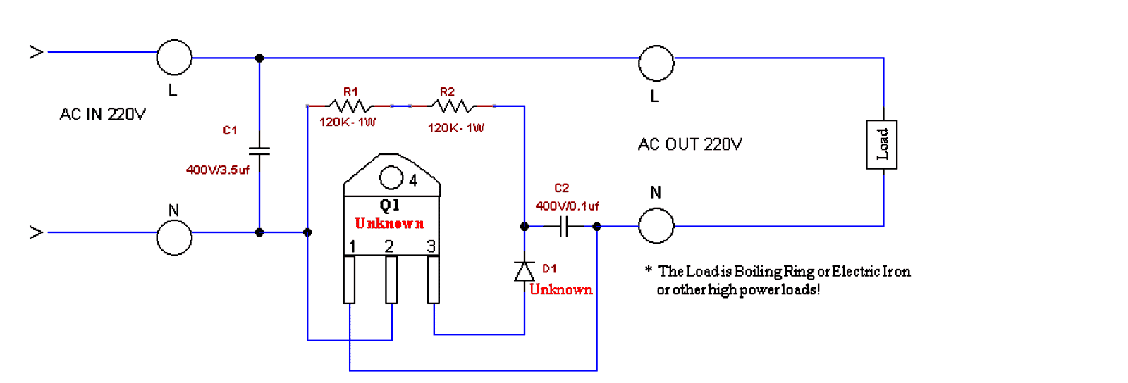
This circuit is a simple AC voltage booster designed for supplying boosted voltage to high-power resistive loads like electric irons or boiling rings. Here's how it works:
Working Principle:
Capacitive Voltage Divider (C1)
The capacitor C1 (3.5µF, 400V) works like a reactive voltage dropper to provide a phase-shifted voltage for triggering the TRIAC (Q1).
It limits the current flowing into the gate of the TRIAC.
Gate Drive for the TRIAC (Q1)
Resistors R1 and R2 (120K, 1W each) form a voltage divider network which ensures a controlled gate drive for Q1.
The combination of D1 (Unknown, but likely a Diac) and C2 (0.1µF, 400V) creates a triggering delay, which allows phase control of the AC waveform.
Switching Action of TRIAC (Q1)
The TRIAC remains off until the breakover (firing) voltage of D1 (could be a Diac like for example a DB3) is reached.
When this happens then the D1 conducts, which sends a sharp pulse to the gate of Q1, turning it on.
The TRIAC then conducts ON, allowing the AC power to reach the load.
Voltage Boosting Mechanism
The phase angle of TRIAC conduction is controlled, which modifies the effective RMS voltage applied to the load.
By partially delaying the triac conduction, the circuit makes it possible to increase the peak voltage for the load.
The increase of the voltage across the load is achieved by extending the conduction duration of the AC cycle.
Main Features:
It Increases output voltage above input voltage (may not bee a true step-up transformer action but rather a phase-controlled voltage boost type).
It will Work effectively with resistive loads (boiling rings, irons, etc.).
This concept Uses phase angle control to regulate output power.
Capacitor C1 is a crucial component which helps to boost the voltage by acting as a reactive impedance.
Limitations:
This design is Not suitable for powering inductive loads (motors, transformers).
Here, the Voltage boost depends on the load resistance and the phase angle.
It Can create harmonics and waveform distortion in the AC supply line of the grid.
Mains Voltage Booster using Two Capacitors and Two Diodes
The above concept can also be implemented with the following circuit which is simpler than the above and is also a lot cheaper.
The capacitor ratings may be modified and experimented with as per the load, and individual preferences.
However this circuit can be used only for heater applications such as irons, heaters, geysers, ovens, toasters, blowers, dryers, hot air gun etc.
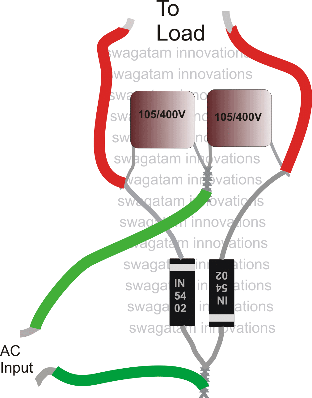
Please use 1N5408 diodes instead of 1N5402, mistakenly shown in the above diagram.
Hello Engineer M. Swagatam
I assembled the Small generator Alternator Power Boosting Circuit successfully as you demystified it missing parts and circuit diagram to be and it works.
It does not multiply voltage. It is still 220VAC in 220VAC out.
I used A pressing Iron of over 1600Watts to test assembled device and it powered the load using my 650W gasoline Gen.
What I want to know now is How to increase the Wattage Capacity of the device.
Would I need to double or Triple e.t.c the TRIAC and or Capacitor and or increase the Resistors Resistance and or Wattage etc.?
Please reply.
Thank you Sir.
Thank you Dare, for updating the results, it sounds great!
To increase the power, you can try increasing the 3.5uF value capacitor to a higher level, and increase the current handling capacity of the triac also, rest everything can be as is…
Tank you for the Prompt Reply. Can I just Double the Triac thereby connect it Pins in Parallel?
I don’t think that will work, you will have to use a single high power triac, such as the BTA41/600 or similar.
Sir. Can booster circuit power AC motor of 750watts from supply of 500watts?
Hello Umar, sorry, that’s impossible on this planet no matter which circuit you use.
Please do you have a booster for the air conditioner
Sorry, I do not have a booster circuit for air conditioner…
OK sir, but can this Ac booster helps in reducing the current been drawn from the prepaid meter
No, this booster is not a power saver device, it is simply to boost a low voltage AC mains into a higher level DC voltage.
Sir, can this circuit power DC motor of same capacity both voltage and power.
Hello King, yes it can power a DC motor, just add a 100uF/1000V capacitor across the motor wires.
Thanks for the response sir, pls I want the fan be controlled by variable resistor so I can decide the speed I like, in this regard I will love have a circuit that has variable resistor sir.
Thanks for the support.
Adebanji, in the previous voltage regulator diagram which I shared, just replace the zener diode with 10k potentiometer, which can be then used to control the motor speed
Good afternoon sir,
Pls there is another project I am working on now I believe later I can come back on the previous project called voltage booster.
Now I designed a project to control the speed of one radiator fan with 30volt dc and as we all know the actual voltage for the fan is 12v dc, so all transistor used when i control the speed are used to have high temperature and blow up.
Pls what can I do? Can you help get another cct for the project?
Hello Adebanji,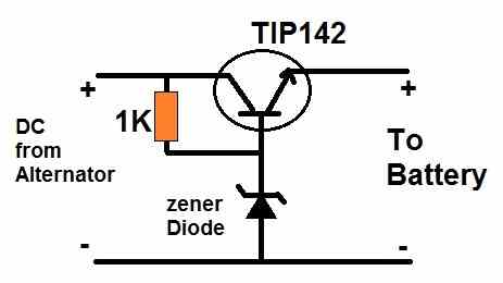
If your fan is 12V then you can stepdown the 30 V to 12V using a transistor regulator circuit, as shown below:
" rel="ugc">
For the zener diode you can use a 13V zener to get around 12V at the output
Dear swagatam,
I have tried your own project in fact I spent time on it but the result I expect I didn’t get it at all.
I use pressing Iron it didn’t work I also used 6a4 diode: 400v 6a , I moved further to use 10a10 diode but its same result.
Pls sir what can I do?
Also you promised to go through the first circuit maybe I should wait for you till you be ready to work on it sir. I remain yours, Thanks.
Hi Adebanji,
Which capacitor did you use in the second circuit? The capacitors are the main elements for boosting the voltage. For your 1400 watt load the capacitors must be rated at least at around 100uF 400V or 630V, and they must be non-polar.
You can initially try using 1uF/400V capacitors and test the heating on your 25 watt soldering iron, you will find the iron becoming red hot due to the boosted voltage.
I really really love you sir. Thank
Kudos ? to our able engineer ? swagatam, I have worked on both circuit but the second one performed well even over performed, I appreciate your effort and concern particularly your response to the questions raised, thanks so much sir. Please ? I need to ask this question, pls like you advised that I can use it
with 1400watts heater, pls what and what can i use? Like the value of components to use. Like value for diode and capacitors. Thanks.
Thank you so much Adebanji, I am glad you could get the desired results from the second circuit.
You can definitely use it with a 1400 watt heater by appropriately upgrading the capacitor and the diode values.
For the diodes you can use 6A4 diodes and for the capacitors you can try 100uF/400V each, they must be non-polar type for best results.
However, please note that if your input power is same as 1400 watts or less then this circuit will not work, in fact no booster circuit will work in that situation.
I have not get feed back from you sir since I made the comment.
Sorry Adebanji, here’s the answer to your comment.
Yes you can use the second circuit for your 1400 watt heater, but you will have to increase the uF values of the capacitors and the power rating of the diodes accordingly to handle the 1400 watt power.
Well done sir, I want to ask if I design this second cct can it be used to power heater, 1400w pressing iron etc, with the explained connections?
Sir,now in the market of nigers the same power booster device (first circuit) has been upgraded to 10000w. Also it’s just performing as they say…… Pl sir why can’t you do something to solve this mystery. It’s a fact that it works well. Further it’s supporting deep freezer and all appliances.
please I need a simple electrical circuit to boost up 30v ac to 240v ac for my electronics appliances at home.
I’m suffering from a very bad low voltage in my area.
pls include the details of the electronic components used and if possible pictorial diagram along side with the circuit diagram.
thanks
You can try the second circuit from the following article to fulfill your requirement. If you are new to electronics then you must first learn all the basics, and only then attempt this circuit.
https://www.homemade-circuits.com/modified-sine-wave-inverter-circuit-2/
what’s the current rating you are supposed to connect?. If higher the current rating it’s very much impossible……! on using 2 nd circuit you lag current.
The current capacity can be increased by appropriately increasing the value of the capacitors and the current rating of the diodes.
Is there any Write up for this project???
What voltage can this produce as output???
What are the pure components used for this project, should incase we want to develop more on it???
Unfortunately there’s no write up for the first circuit. I can provide more details about the second circuit if required.
Regards.sir. With the circuit power booster can we connect lighting loads. Have you developed any thing like this sir. If so pl update me.
Hi Raja, I have tested the last circuit with my soldering iron and it became red hot within a minute. So if it works with a soldering iron then it should work with lights also, provided the light is an incandescent type.
How to make booster for generator
Hi i am a final year, student of electrical and electronic engineering department, my project topic is Ac to Ac based power booster range from 500watt, to 1500watt.
AC to AC power booster can be built only through transformers.
And a 500 watt to 1500 watt power can never happen because power can never be boosted. Either current or voltage can be boosted.
But Sir, will the circuit pick my iron? Since the output is DC
resistive loads can work equally well with AC as well as DC, no issues.
Because I sincerely wish to use either iron or heater on it and the are all ac load. Please kindly help me out Sir
Patrick, You can use the second design to get increased heat on heaters and irons.
Sir , please how can I turn the output to ac instead of DC
Sorry that is not possible. Instead you can use heavy duty transformers to achieve that.
Because I design the two circuit but non of them work for me. It will indicate light on socket but if on load, it turned off immediately
Which circuit are you referring to? The second circuit in the above article is tested by me and it worked perfectly for my soldering iron.
Sir , I’ll be very grateful if I have the complete circuit label. Thanks
Patrick, which circuit are you referring to?
Precisely the first circuit Sir
I did not test the first circuit it was contributed by another reader.
Good morning Sir, please the second circuit, how many watt is it and can I use 1000watt iron on it
Hello Patrick, the output watts will depend on the values of the capacitor and power of the diodes. But it is applicable to only resistive loads such as soldering iron, bulbs, heaters etc.
i wish a happy day swagatam.What is the value of the watt at the output of the circuit? thank you.
Thanks Abu, For the second circuit the output can be 100 watt
Thank you, but what are the modifications to produce 1800 watts to supply a home heater without damaging the circuit?
The above circuit can be used only for resistive loads, and not for any other form of loads.
What value of capacitor will I add up to obtain 1000watt output Sir
You can try 100uF/400V PPC and 6A4 diodes
Please do you mean paper Cap by “PPC”
Polypropelene capacitors or metalized polyester capacitor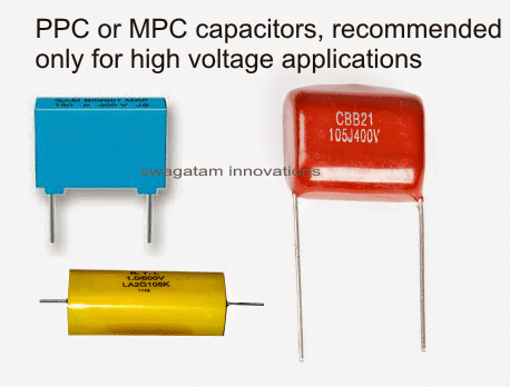
" rel="ugc">
Compliments engineer, can a NTC thermister be added to the circuit you suggested for the alternator power booster so that it can as well power an inductive motor. If possible, the circuit diagram please.
I don’t think an NTC thermistor would be able to upgrade the circuit to handle inductive loads…it doesn’t seem feasible.
In the first diagram with traic . I was able to come in contact with the guys selling it. This is the explanation given to me
“The only work it does it to enable you Plug things you cant Plug directly with your generator for Instance an IRON cant be plugged on a small 800VA I better Pass my neighbor generator, so what the Power Optimizer does is to Decrease the Power consumed by the Iron and enable the Generator Power it. Also Note thate the Power Optimizer for Elements Like IRON, Water dispenser, Hot Plate, Electric Cooker Can not be used for Compressors Like AC, Freezer, Fridge, Pumping Machine, etc.”
Please honorable is it possible for a device to reduce the output power of appliance to enable the input power to power it?
Please what’s on take on this?
I bought it used it with my little generator and 1000w pressing iron and it worked perfectly.
Hi Emmanuel,
Sorry I did not understand your following statement properly:
Sir ple I want to ask a question sir., Like the AC booster using 2capacitor and 2diode. Can I use it for electronic TV or radio etc. Sir sincerely need your reply. God continuing to bliss you sir
Maxwell, this AC booster circuit cannot be used for inductive or capacitive loads like TV or radio, it can be used only for resistive loads like heaters, soldering iron etc
Please what’s the difference between BT139, 600E, D2 series and BT139, 600E, A2 series in transistors
Please I need your help on that. Thank you
Sorry Emmanuel, I have no idea about it. What are D2 and A2?
Would I need a transformer for this alternator booster?
What IC can I use to produce this??
How and what can we use power booster to raise capacity of power generation. Like 5kva to 10 kva pf.?
This circuit is designed to work only for resistive loads, not for inverters or inductive loads
Good day
I have a fivestar 1000w 12v to 22ov inverter but have some problems with it. The output is only 183v ac. how can I boost the output to give 220v ac.
I checked my 2 batteries and the DC is 13.5v.
Also can u please help me to increase this to a 2000w if possible. And a diagram to explain where to put extra mosfets.
Kind regards
Please check the battery voltage after connecting a load to the inverter. The battery voltage might be dropping while a load is connected which may be causing the output to drop as well. If the battery is not dropping with a load and still the output is dropping then your inverter is malfunctioning, and will need to be checked and repaired.
To upgrade inverter power output you will need to replace its transformer, mosfets and the battery appropriately as detailed in the following article:
Calculate Battery, Transformer, MOSFET in Inverter
Please sir i want to ask you a question, 1N5408 DIODE and 1N4007 DIODE which one is higher, and which one is lower
1N5408 can handle more current.
Please sir.can i use 1N4007 diode with 105/400v capacitor to build this booster
you can use it.
Please sir if i use 1N4007 DIODE and 105/400V CAPACITOR can it give me high current or low current, and can i use it to iron my clothes on my i pass my nabbour generator
Good day to you sir, I really love the way u respond to our questions here God will bless you, like I have came across this post b4 some years back, pls my question is, can this second cct be used to power pressing iron, heater when connected it to small 800va generator?
Thank you Adebanji,
Yes you can use the diode/capacitor to power pressing iron, heater when connected to small 800va generator
Please sir,I want to ask you a question, The question goes like this, apart from CAPACITOR NUMBER 1N 105/400V and DIODE NUMBER 1N 5408, can i any other number of capacitor or diode to build this power booster.please sir I need your answer
Hello Chukwuma, you can use other values for the capacitor, but lower values might give lower current output, and vice versa. However the voltage value must not be below 400V for a 220 V AC input supply
Hello honourable swatagam,how are u doing,I have an issues,1. how can i make 220vac transformer less to 10vac .
2. How can I converts or stepdown already 150vac to 10vac bcus d existing transformer in this one which suppose to stepdown 150vac to 9vac – 10vac and I could not get such transformer for replacement,very small transformer wit low ma, is now producing or giving out the same 150vac instead of 9vac – 150vac Tobe the correct output of powering a small logic board wit small lcd on it.
Hello Nosa, if the output current requirement is lower than 50 mA then you can convert 150V AC to 10V AC using forward/reverse 10V zener diodes placed across the supply lines.
Thanks my honourable swatagam,I will check it out
You are welcome Nosa!
Hello my honourable swatagam,you said 10v zener diode should be placed across the supply line’s. Do you mean the 10v zener diode should bridge the live and neutral connection or wires.
When you said forward/reverse,it therefore means that when output device is connected the 10v can flow from N wire terminal or L wire terminal,is that what you met by forward/reverse
Hello Nosa, you can try the following configuration
" rel="ugc">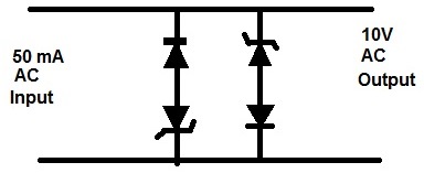
Thanks my honourable swatagam,your diagram is very simple,if i may get u,do you mean dat the main power supply input from 220vac to 240vac transformer less comes into your diagram and the output is 10vac.is that what the image explain or showing.
Thank you Nosa, yes that’s correct a 240V AC at 50 mA current can be fed to the circuit for getting 10V AC.
Thanksy honourable man
Good morning Sir, please I design the same circuit but the output is reading 110v and if on load , no output at all. Please I need urgent solution
Hi Patrick, How can that be possible, because the zener diodes are 10V rated? Try by connecting a small load, such as a 1K resistor
Thanks my honourable swatagam
Hello swagatem,happy new year and how are you be doing,my question is this, is it possible to pour in distiled water into deep circle battery for solar and charged it up,can d dead battery come back to life.
Hello Nosa, Happy new year to you. Distilled water can be used. The battery may start working if the chemicals inside the battery are still in usable condition.
Thanks Mr swagatem maybe I should give it a try.
I have 12v 230ah deep circle solar battery totally drain out to 2v and I try charging it wit solar panel which it refuse to charge up and I design 12v charging system to charge it but d wires are very very hot during charging and burnt up,so what should I do because d battery voltage still remain 2v in it and it fails to increase to 12v upward.
Connect a series 12V car headlamp bulb with the positive wire, and continue charging for many hours.
Thanks my honourable swagatam.
I have a question, concerning earth battery,how possible for it to power duplex and others.from what I saw on the Internet earth battery is usually 2v charged,so how do I get one bank as 12v 230ah or 400ah etc.how do I design or build such earth battery.pls give me links doing that
Sorry I have no idea about it.
OK thanks my honourable swagatam. Love u big time.cheers
It’s my pleasure Nosa!
My honourable swagatam,please tell me why you said I should connect 12v series of car head lamp bulb with the positive wiresults.
Hello Nosa, as you said that the wires were getting very hot during charging, this could be due to very high current or a shorted battery. A bulb in series will ensure that the current to the battery is controlled, and the wires do not heat up. The bulb will remain illuminated initially and as the battery gets charged the illumination will slowly decrease until the battery is fully charged. If the bulb illumination does not decrease will mean your battery might be faulty. The bulb can be connected in series either with the positive line or the negative line….
Thanks my honourable swagatam, pls whats your recommended voltage to charge a 12v 200ah to 500ah battery or as from 40ah to 500ah 12v battery of deep acid lead circle battery or tubular acid lead battery.
Hello Nosa, the voltage for charging a 12V lead acid battery is 14.3V but you can limit it to 14V for better safety. The current should be around 1/10th of the Ah value:
Lead Acid Battery Charger Circuits
Thanks my honourable swatagam,I was using 18v to charge 12v 200ah deep circle battery I told u about maybe dat was the reason the was very hot and getting burnt.
Yes that may be exact reason why your wires are getting hot
Thanks my honourable swatagam, now my voltage is 18v can I use potimeter or variable resistor to reduce my voltage to 14v or 14.3v To try it back on 12v 230ah deep acid lead battery to charge it again or can I connect it to a 60ah pwm charge controller to charge 12v 230ah deep circle battery without reducing the voltage to 14v,can dis method work without having effect on the 60ah pwm charge controller.
Thank you Nosa, you can connect the 18V with the following circuit and then adjust the pot to reduce the output to 14.2V:
Thanks my honourable man
You are welcome Nosa!
Hello my honourable swatagam, can I join charge in paralle 12v 230ah deep circle battery that is drain to 0v to 2v with 12v 100th deep circle battery that is very good and fully charged to use it smart chargers Tobe able to charge the dead 12v 230ah deep circle battery.
Hello Nosa, no, you cannot charge the deeply discharged battery with a charged battery, because then the charged battery will also get fully discharged, and neither will get charged.
You must use a 14V 25 amp charger to charge your 12V 230 Ah battery
Hi Mr. Swagatam iam 62 years old man ritrired from Civil Aviation but iam ingage for life i see your all Electronic circuits and istady i liked your work
Best regard
zafar
Thank you Mr. Zafar, I appreciate your interest and glad you liked my work.
Sir thanks for your technical teaching, please I need a circuit that can help me boaster my generator current power so that it can withstand more loads without changing of sound pls
Thank you Emmanuel, sorry, presently I do not have any circuit for boosting generator power output.
Good morning and thank you for sharing your knowledge with us. I am searching for a circuit to step up 15v ac provided by my doorbell ring wires to 18-20v ac in order to use it with video doorbell. A solution is to change the transformer but I am wondering if there is other solution in order to avoid changing the transformer for 3-5 volts diferrence. The video doorbell needs about 300ma. Thanks in advance , waiting for your answer.
Hello, the easy and better solution is to change the transformer, because making a boost converter can be rather complex, and might require some advanced knowledge in the field.
Please the 1 and 2 of the triac terminal, are they connect
No, joints are shown in black dots
Hello Mr swagatam greetings, am impressed wt ur innovations more power to ur elbows. Plz I need voltage booster my generator alternator coil 230V goes down when I put loads esp small refrigerator of 50 litrs (freezer) wt other little appliances, so want to boost the voltage to 300V for easy carriage of the loads. I reside in Ikom Cross River State Nigeria, I’ll fund d cost of the boost, tell me the cost. My email jobnwobegu007@gmail.com. thanks in anticipation of your response
Thank you jofrancis, the voltage could be going down due to heavy current drawn by the freezer, which cannot be corrected with a booster, instead you may have to upgrade the alternator power with increased current rating.
please sir I really need your help on the write up based on the circuit requirements,design, explanation, analysis and circuit diagram on alternator power booster
It is not possible to boost power of any source, output power will be always less than the input power
I builds the second circuit with exact components but no outputs, and all the components are in good conditions.
thank you Michael,plz i need this generator booster circuit diagram that can carry AC electric motor at least 1/2 or 1.0 HP, unlike the one that carries only boilers and heating elements . i love your works.Thanks and waiting.
Mr. Micheal (Warbabylon) can help us with the complete circuit. Many of us are yet to get this circuit working. Thank you as you share.
the last one has been tested by me, not quite sure about the first one…
Please can this second one power air condition?
This is my email… Sir so pls…. Help me… Sir. Aljohnguigue@gmail.com
Sir can u help me with my project in school….. I want to know on how to make a power booster…. With the help of you…..sir.. Example. When I have a 3000 watts generated power..I want it to boost into 6000watts or something higher than 3000 watts..
Aljonguigue, that’s a technically impossible thing to achieve, you can never boost power. you can boost voltage or current, but the output net V x I will be always lower than input V x I
the circuit above with triac operates on the principle of controlling the firing angle of the triac
Hello swagatam, am really glad meeting your post on this. Actually I've seen a generator booster that you can actually use with electric iron and heater. At the moment, am trying to reconstruct this circuit believing I will get my required result of a booster. I have all the components from the above diagram and am about to test it out. Please I have a 104/400v capacitor and a 3.5uf/400v capacitor mostly found in ceiling fans. I hope it will do the trick. Pls am really concerned about the booster circuit and I humbly ask you to throw more light on that. Thanks
Thanks nnaemeka, a booster will work only if the input source has enough stock current, if it lacks current then the booster will fail to sustain the load.
you can use the mentioned fan capacitors for the second circuit…the shown design has been tested by me with a soldering iron and it worked perfectly making the iron red hot within minutes, and I had to switch OFF the supply to prevent the iron from burining.
OK please if you yes matter to read the voltage how many volts are you seeing?
hello ive tried it using the fan capacitor and didnt get a feedback. please what should i do? Also, i saw a picture circuit where 13005 transistor was used with two 100k resistor, one 16k resistor and a ceramic capacitor probally a 1uf/400v. i coundnt get the actual circiut diagram. pls could you help me discover if the above components can be used effectively to boost electrical equipments like electric iron and heater. Thanks
hello, I had used PPC capacitor in the second design, I could instant results from it, I am not sure why your capacitors didn't work?
The diagram at the top is the only one that i have, which was given to be by one of the readers.
..I do not have much idea regarding the working of the first diagram as I am having difficulty in simulating it in my mind…so I can't help you with it…
yeah,I like electronics , its most important and usefull thing in the world,but am still getting up in to it, i need an inverters way at an electronics ,I need help Swagatam
Thanks Nukuba, if you have any specific questions, please feel free to ask…
Hello once again sir Swagatam..
can i use this 2 non polar cap. 105J400V and 2 IN4007 instead of IN5408? its not available here.
Thanks Again..
HiPaul, yes it will do…two parallel 1N4007 may not be required, you can use single 1N4007 diodes since the load in your case is small….
Dear Swag, thanks for your article. It’s very informative. Please is it’s possible to have a circuit diagram that can work with an Air conditioner. And secondly, what does Booster Capacitor do and how can one be designed.
Thanks.
Sixtus, for an air conditioner you will need a transformer, a capacitive circuit might not work. The capacitor in the second circuit add their stored voltages in series to create a doubled voltage at the output
hello sir Swagatam,
Our grid is 170 volts which is a low voltage and my soldering iron is rated 220 volts 40 watts?
can this be helpful to power up my soldering iron?
thanks again sir..
yes the circuit will work for raising the 170V to 230V and more
Hello Sir Swagatam..
Can i use this 2nd circuit for soldering iron that is connected to a low voltage grid?
Thanks in advance…
Hi Paul, yes you can do it…
Can this work on solar powered inverter?
Engr.Swagatam
I commend u for this wealth of knowledge you always made available to anyone who demand of it.my question is; can a variable resistor and additional capacitor be use to vary the amount of current that the load receive.In due course I will upload another circuit of the same function with the one mr Michael uploaded for your input and analysis. this is because this circuit has a variable resistor of 250K
Thank you Gabriel,
Actually I am not sure about the first circuit since it was drawn by assuming the stages.
in the second circuit the current is controlled by the capacitor values….however this cannot be made variable.
If you have a more appropriate diagram you can surely send it to me for publication.
Thank you very much!
A generator output is mainly dependent on the RPM of the alternator, which is governed by the correct timing of the CDI sparks….so may be the CDI sparks are not firing correctly in the ignition chamber of the generator…so perhaps this issue could be identified and rectified appropriately
hello, thanks you…I had tried it successfully on a 25 watt soldering iron but yours is a 1000 watt press iron which might require a huge current….therefore the capacitors must be rated accordingly, may be upto 50uF to 100uF….but should be non polar type….you can try connecting many 105/400V capacitors in parallel for acquiring the results.
hello sir how was your day. my 1hp eletric pump affect my generator when ever i use it to pump water. is there any circuit solution for this to add to my 2.5kva generator to power it.
hello olutayo, a 2kva generator should easily handle a 1hp motor, you must first check how much current the motor is trying to draw for the pumping operations, if it's more than 5 amps then probably you may have to replace the generator with a higher rated model.
Sir, still on this matter: if am able to buy one and send it to you will it help to solve this mistry and share the knowledge as you have been doing so kindly?
In all honesty your kind is very rare.
I want to say again that am highly impressed and humbled by your openess and willingness to share what you know and guide others like me without attaching a price.
People ask same questions and you patiently give answers and where you do not know you are humble to admit. Thank you, thank you and thank you again.
Am learning bit by bit, I loves electronics hopefully someday I will be good and able to help others too.
Finally, I did write you requesting for a circuit to help me charge my nicd drill batteries. You promised to look into it. Just a friendly reminder
Thank you so much Nwachukwu, actually I have already published it in this site…you can check it out here:
https://www.homemade-circuits.com/2016/05/cordless-drill-battery-charger-circuit.html
Ok sir. Which circuit should I work on?
Secondly if it's the second one, does it require a transformer because transformer was mentioned in one of the comments yet I didn't see a transformer in the circuit. Please help me out.
I have tested the second circuit with my soldering iron and it worked perfectly…so you can try the second circuit…transformer will not be required, just connect the source supply across the shown input wires, and the output wires can be connected with the load.
adding more capacitors in parallel will allow you to get more current for the load
From Onyenkwere Chinaza.
Please I use a 1000W pressing iron and I use a 650VA small generator. Does it mean that this circuit can help me use the iron with the generator?
If yes which circuit will work. The first or the second?
In the second is there a transformer involved?
Forgive me for the many questions, I'm a newbie in this field.
No, the above circuits will not increase wattage or power, these circuits will only boost the voltage to double or triple values
I have to agree with my fellow Nigerians that this thing WORKS… Its still kinda strange to me how the circuit could possibly make a 500W generator power a 1500W electric Iron, but somehow it works…perfectly in fact….for heating applications only though. Iron, cooker, electric kettle, .. It goes crazy on any other kind of load like a fridge…. I'd really like to know how this works… The mystery is eating me…
Good day sir, I tried building the circuit using the two capacitors 105, 400v and the diode connected as shown in the circuit diagram but is wasn’t giving me an output voltage sir.
Eben, It should give two times more voltage than the input, if the input is 240V , the output should be 500 V, please check the parts and connections properly.
Hi michael…..good day,i'm Francis…..please could you share the circuit with me?!!!!!!!!?
Hi.
I want to view Posted circuit pictures. How do I view them because they don't seem to appear when I click on them?
Hi, place the curser over the image, and click when it turns into a "hand" icon
Hi Mr swagatam please can you device a circuit that can power fridge using
Triac diac and Micah capacitor please I need it urgently thanks Emmanuel Obayagbona
Hi emmanuel, can you please specify what exactly are you trying to achieve…if it's getting more output than the input then I am sorry that's impossible and not feasible….
But Mr swagatam,is there no alternative booster circuit Tha can power a fridge using tiger generator??
can you specify the input power specifications and the fridge voltage and watt specifications, to be able to understand the situation.
Dear swagatam,
What rate (in VA) ur circuit above, and can it use for air conditioner 1hp inverter?
Dear Yuzie,
the above circuits will work only with resistive loads not with inductive loads, and an inverter is an inductive load.
as i posted earlier, i bought one of those power optimizer and i use a 650va generator set (called i pass my neighbour). this gen can not power up a 1500watt electric iron or heater but with the use of the optimizer/ power booster i was able to iron effectively and heat up my water several times and the first diagram looks exactly like d one i have. how i wish there is a way i an send u a snap shot of the components so u take a look at it yourself
if you are able to generate 1500VA from a 650VA source by any method then that's a miracle and you must show it to the world, the idea can you a millionaire.
As for me I have no idea how to do it, as I told you before I am unable to simulate the first circuit so can't help with it.
a snap shot will not help because that will not reveal the circuit details or the component details of your circuit
I BUILT THE SECOND CIRCUIT YOU GAVE SIR BUT IT DIDNT WORK. WHEN I PLUG IT TO LIGHT THE SOCKET COMES ON BUT WHEN I PLUG AN ELECTRIC IRON TO THE SOCKET, THE LIGHT GOES OFF BUT MY GEN REMAINS ON. PLS WOT EXACTLY COULD BE THE PROBLEM. I NEED UR HELP PLS
I am not sure what you are trying do?
If you are thinking that this circuit will boost wattage then you may be wrong…the circuit will not boost wattage.
if your iron wattage is too big for the generator then no circuit in this world would be able to make it function.
the second circuit above will not boost voltage provided the wattage of the load is much smaller than the wattge of the fed input
….sorry I meant
the second circuit above will only boost voltage provided the wattage of the load is much smaller than the wattage of the fed input
am confused sir u said and i quote "The capacitor ratings may be modified and experimented with as per the load, and individual preferences". what exactly do u mean by this? is it that the 105/400v can be increased or reduced? if that is true what will be the effect of such increase or reduction? also if i have a 600va gen set and i want to use a 1500watt iron on it, will ur modified circuit work? if no what do u advice?
yes you got it right, by increasing the uF of the capacitors in the second design you can increase the current or the wattage handling capacity of the circuit
but you cannot increase the output wattage than the input wattage by using any method, anywhere in this universe, that's not feasible.
pls sir i bought one of those power optimizer as it were called and dismantled it and the circuit looks exactly like the first one uploaded and it was working fine but when i dismantled it, i discovered that the component numbers were wiped off, so my question is this, cant the first one work owing to the fact that it really worked when bought and secondly what is ur take sir. pls reply me and once again thanks for educating me alot
Ekeh, if it was working before means it is a good design, but may be you broke something while trying to dismantle it, there must be something that was hidden and secret which you might have broke and that's why it isn't working now….
I am finding it difficult to simulate the first design so I can't suggest my opinion about it.
thanks for your explanations on this booster. actually I have built the first circuit by mr Michael and I connected the positive to Q1 instead of negative and the device worked without any humming noise but when I reversed my connection to as it is in the drawing above I.e with negative to Q1 I discovered that the device was humming, and also I connected a metre to the output socket the output with out load was 50v but with load 100v. please can you explain these my discoveries.
more so, instead of a ceramic capacitor can't I use polarised ones because I have 4700uf 25v &1000uf 25v and I have IN5392MIC.
lastly can I use a diode instead of diac? thank you.
to me the first circuit doesn't make any sense at all. C1 is connected directly across the power rail meaning it will only waste power and do nothing.
even if the circuit works it won't do anything significant.
the second circuit suggested by me has been tested by me and it really works, but only for resistive loads such as heaters
4700uF/25V will give you a big explosion.
please what will happen when there is high or normal voltage conditions, won't it blow up the appliances?
yes it will damage the load (resistive only) if the input voltage is restored back to normal.
Mr. Swagatan, please what exactly is the booster used for or what is the purpose of the booster?
Mr Eno, in the above shown circuits it's for boosting the performance of resistive appliances during low voltage conditions.
It will take time…just keep investigating the circuits and the concepts theoretically and practically, when in trouble put up your question here to get them answered appropriately…in this way you will be able to gradually grasp the many aspects and get stronger in the field.
it should be 105/400V not 104/400V. 104 = 0.1uF, 105 = 1uF so pls correct this in your circuit.
please mr swagatam how can i make the above circuiy yo power a refrigerator
the above circuits will work only for heater types of resistive loads, not for other appliances.
Can i use it with microwave, connect to my 1.5 inverter
It's not recommended, but you can give it a try, if there's no audible noise from the fan then it could be fine.
Will ceiling fan capacitor work that is non polar capacitor? Pls help. Am waiting for ur reply sir.
yes it will work.
I think the triac use in mr micheal cct is BT151 but the diode I can't tell. Pls try complete the cct ƒσя ♏ε̲̣̣̣̥
Interesting but can I use it with my inverter 1.5 inverter
It is recommended for resistive loads only.
1N5401 is not a problem, and if you are using a soldering iron at the output even a 1N4007 will work as diodes.
check the capacitors, they might be faulty.
It would be difficult to troubleshoot without seeing, actually my prototype worked very well, in fact the connected soldering iron became red hot within a minutes time and I had to switch power off to prevent the iron from blowing off.
everything's already furnished in the above article.
Hello Mr. Swagatam. Please can this voltage booster be used for induction loads like centrifugal pumps, air conditioner, fridge, and motors?
Hello Prince, A voltage booster based on transformers can be used with all types of equipment, but the above mentioned concepts are suited only for the resistive loads.
Mr Swagatam, I really appreciate your prompt response. Please do you have any such “transformer-based voltage booster ” circuit?
Best regards.
Hello Prince, you can refer to the following article which shows how to connect the secondary of a transformer with its primary in order to create a voltage boost
https://www.homemade-circuits.com/how-to-build-2-stage-mains-power/
Mr Swagatam, appreciated.
Good day sir your article is really inspiring,pls can i use this circuit with my 1.5kv inverter to use my i.2kv microwave
Thank you Hyelda, no you cannot use it for inverter, it is only recommended for resistive loads.