In this post I have explained how to make a 0.6V to 6V or 12V boost converter circuit using a single chip MC74VHC1G14, which uses under 1V to operate.
About the IC MC74VHC1G14
Normally, we all know that a silicon transistor would find it difficult functioning below 0.7V, unlike germanium counterparts which are capable of doing it with ease, however nowadays we don't often hear about these devices which have become quite obsolete with time.
The circuit discussed here uses an inexpensive Schmitt trigger NOT gate MC74VHC1G14 from the 74XX TTL family which are designed to work with voltages well below 0.6V, to be precise even with as low as 0.45V. The device we employ is manufactured by Motorola.
The presented 0.6V to 6V boost converter circuit can be even modified to achieve upto 12V from a 0.6V source.
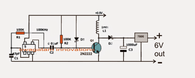
Referring to the figure below, we see a rather straightforward set up consisting of an oscillator stage using a single NOT gate inverter module as discussed above.
You can also try a Joule Thief Circuit for getting similar results.
Another design explains a 1.5 V to 3.6 V boost converter circuit
Circuit Operation
This NOT gate is very special since it's able to oscillate even at voltage as low as 0.5V which makes it very suitable for the present 0.6V to 6V or 12V boost converter application.
The oscillation frequency here is determined by R1 and C1 which is calculated to be around 100kHz.
The above frequency is fed to the base of an NPN transistor for the required amplification.
C2 makes sure the two IC and the BJT stages are kept isolated from direct contact in order to avoid the low input voltage from dropping below 0.5V
R2 and thee schottky diodes D1 keeps the BJT sufficiently biased for helping an optimal oscillatory response for the transistor.
D2 is another schottky diode which is introduced to keep the charge from C3 disconnected during the switch OFF periods of Q1 otherwise the stored charge inside C3 could get discharged or shorted via Q1.
The IC 7806 at the output is to maintain a fixed 6V irrespective of the boost level created by L1 and the associated converter stages.
L1 must be wound strictly over a ferrite core. The dimension and data of the coil is a matter of some trial and error or it may be procured as a ready made unit for the same.
Circuit Diagram


With over 50,000 comments answered so far, this is the only electronics website dedicated to solving all your circuit-related problems. If you’re stuck on a circuit, please leave your question in the comment box, and I will try to solve it ASAP!