In most automatic battery charger circuits in this blog you might have seen an opamp with a hysteresis feature included for some crucial function. In the following post I have explained the significance and design techniques for the hysteresis function in opamp circuits.
To learn exactly what's a hysteresis you can refer to this article which explains hysteresis through an example of a relay
Principle of Operation
Figure 2 demonstrates a conventional design for a comparator without employing the hysteresis. This arrangement works by using a voltage divider (Rx and Ry) to establish the minimum threshold voltage.

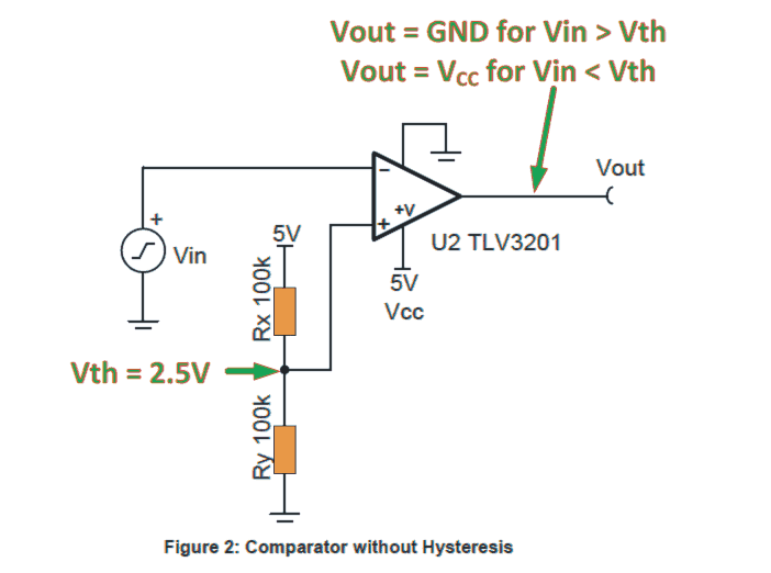
The comparator would evaluate and compare the input signal or the voltage (Vln) to the set threshold voltage (Vth).
The comparator input feed voltage which is to be compared is connected to the inverting input, as a result the output is going to feature an inverted polarity.
Each time the Vin > Vth the output is supposed to get close to the negative supply (GND or logic low for the shown diagram). and when Vln < Vth the output would get close to the positive supply (Vcc = 5V or logic high in this example).
This easy solution enables you to decide whether or not a genuine signal for example temperature is above a given decisive threshold limit.
Even so, using this technique may possess a predicament. Interference on the input feed signal could potentially cause the input to changeovers above and below the set threshold triggering an inconsistent or fluctuating output results.
Comparator without Hysteresis
Figure 3 illustrates the output response of a comparator without hysteresis with a fluctuating input voltage pattern.
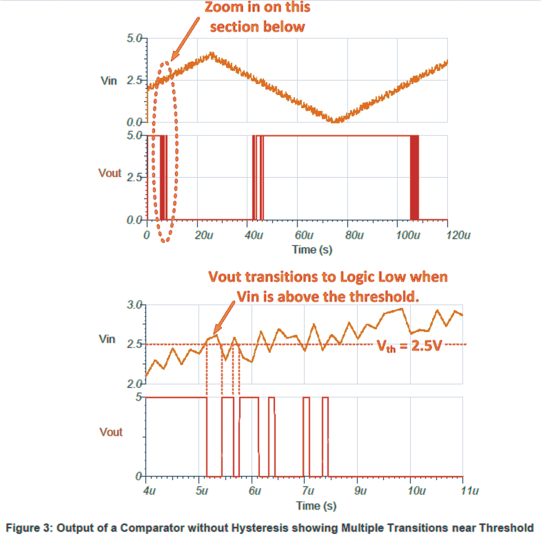
While the input signal voltage arrives the set limit (by the voltage divider network) (Vth = 2.5V), it adjusts above as well as below the minimum threshold a number of instances.
As a result, the output fluctuates too in accordance with the input. In actual circuits, this unstable output may easily cause unfavorable issues.
As an illustration, think about the input signal to be a temperature parameter and the output response to be a crucial temperature based application, which happens to be interpreted by a microcontroller.
The fluctuating output signal response may not contribute a faithful information to the microcontroller and could produce "confusing" results for the microcontroller at the crucial threshold levels.
Additionally, imagine that the comparator output is required to operate a motor or valve. This inconsistent switching during the threshold limits could force the valve or motor to be switched ON/OFF many times in the course of the crucial threshold situations..
But a "cool" solution through a modest alteration to the comparator circuit enables you to include hysteresis which in turn completely eliminates the jittery output during threshold changeovers.
Hysteresis takes advantage of a couple of distinct threshold voltage limits to stay clear from the fluctuating transitions as seen in the discussed circuit.
The input signal feed needs to go over the upper threshold (VH) to generate a changeover of a low output or below the lower set threshold limit (VL) to switch over to a high output.
Comparator with Hysteresis
Figure 4 indicates hysteresis on a comparator. The resistor Rh locks on the hysteresis threshold level.
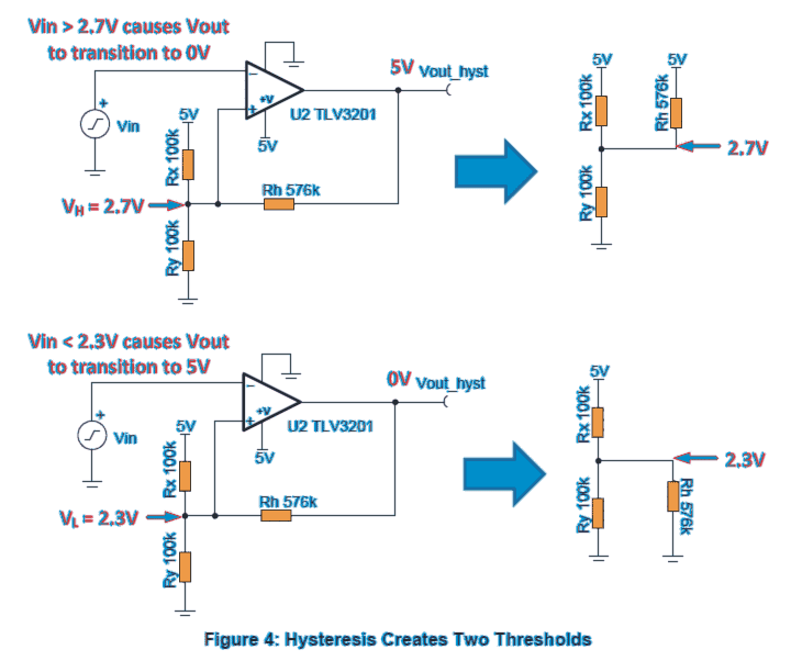
Each time the output is at a logic high (5V), Rh remains in parallel with Rx. This pushes extra current into Ry, elevating the threshold limit voltage (VH) to 2.7V. The input signal will likely need to go above VH=2.7V to prompt the output response to move to a logic low (0V).
While the output is at logic low (0V), Rh is set parallel with Ry. This cuts-down on the current into Ry, bringing down the threshold voltage to 2.3V. The input signal will want to go below VL=2.3V to settle the output to a logic high (5V).
Compartaor Output with Fluctuating Input
Figure 5 signifies the output of a comparator with hysteresis with a fluctuating input voltage. The input signal level is supposed to move over the higher threshold limit (VH = 2.7V) for the opamp output to slip down to logic low (0V).
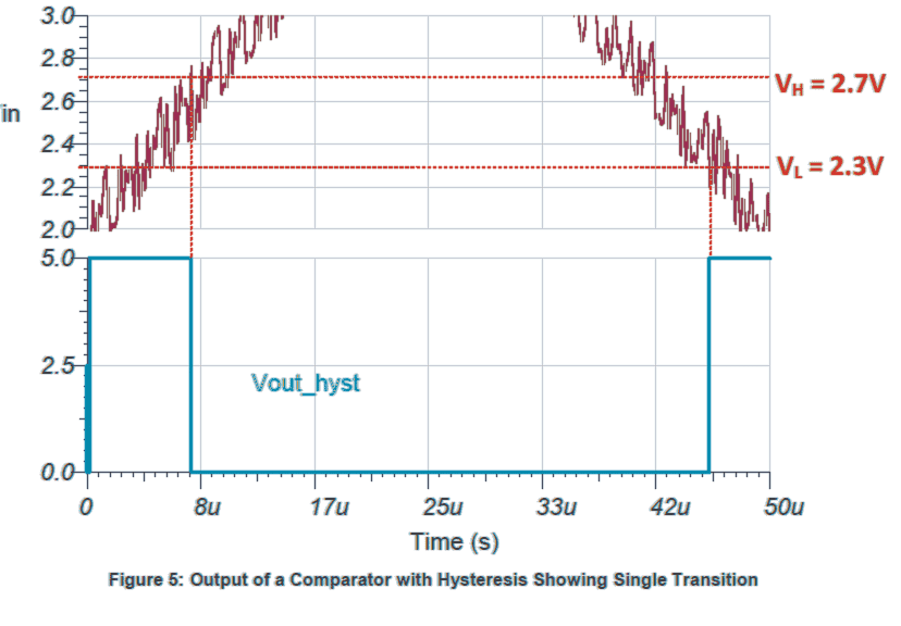
Also, the input signal level needs to move under the Lower threshold for the opamp output to smoothly climb to logic high (5V).
The disturbance in this example may be negligible and therefore may be ignored, thanks to the hysteresis.
But having said this, in cases where the input signal levels were above the hysteresis calculated range (2.7V - 2.3V) could result in generating supplementary fluctuating output transition responses.
To remedy this, the hysteresis range setting is required to be extended sufficiently to dismiss the induced disturbance in the given specific circuit model.
Section 2.1 provides you with a solution for determining components to fix the thresholds in accordance with your selected application demands.
Design of Hysteresis Comparator
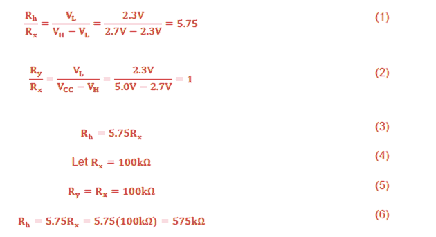
Equations (1) and (2) can be of help to decide upon the resistors wished to create the hysteresis threshold voltages VH and VL. A single value (RX) is required to be arbitrarily picked out.
Within this illustration, RX was determined to 100k to help reduce current draw. Rh was computed to be 575k, accordingly the immediate standard value 576k was implemented. The confirmation for Equations (1) and (2) is presented in Appendix A.
Rh / Rx = VL / VH - VL
Discussing hysteresis with a Practical Example
We take the example of a IC 741 battery charger circuit and learn how the feedback hysteresis resistor enables the user to set the full charge cut off and low charge restoration of the relay apart by some voltage difference. If the hysteresis was not introduced the relay would rapidly switch ON OFF at the cut off level causing a serious issue with the system.
The question was raised by one of the dedicated readers of this blog Mr. Mike.
Why Reference Zener is Used
Question:
1) Hi this circuit is very genius!
But I have some questions about the comparator opamps;
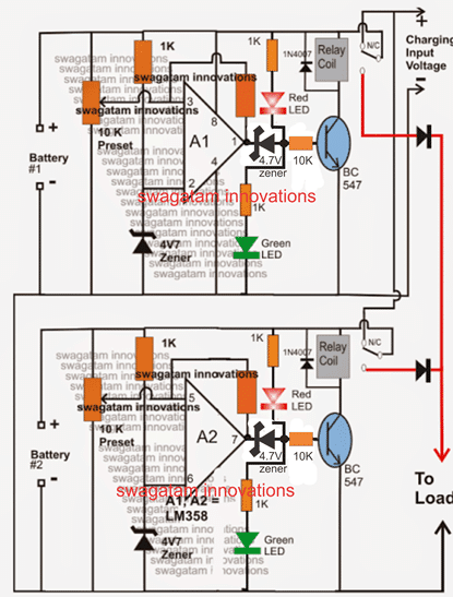
Why are 4.7 zeners being used for the reference voltage? If we don't want the 12 volts to drop below 11 for discharge,why such a low zener value?
Is the feed back resistor going to the virtual ground point a 100K resistor? If so, why was this value chosen?
Thanks for any help!
2) Also, I apologize, I forgot to as why are there 4.7 zeners at the bases of the BC 547 transistors?
3) Also my last question for today for this circuit. The red/green indication LEDs; how do they light up? I mean the red LED is connected through its resistor to the top + rail, connects to the output of the OPAMP, then goes down in series towards the green LED.
It would seem they wouldbe both on at the same time, since they are in series, in both circuits.
Does it have something to do with the feedback circuit and virtual ground? Oh I think I may see. So when the OPAMP is off, the top red LED
Current is going through the feedback resistor (thus its "on")to the virtual ground point? But how does it get switched off, when the OPAMP has an output? When the OP AMP gets an output, I can see that going down to the green LED, but how, in that state, does the red LED then get switched off?
Thanks again for any help!
My Reply
4.7 is not a fixed value it can be changed to other values also, the pin#3 preset ultimately adjusts and calibrates the threshold as per the selecte zener value.
Question
So the reference voltage is the zener is at pin 2 (top view opamp) correct? The 100K feedback resistor and pot are creating the hysteresis value (meaning, the difference between pin 2 and 3 to make the opamp swing high to its + rail voltage)?
The opamp in this config is always trying to make pins 2 and 3 arrive at the same value via its feedback resistor, correct (zero, since the feedback divider is @ 0 and pin 3 is @ ground)?
I've seen this solar charger controller done without the feed back, just using several opamps with voltage reference pins and a pot on the other one.
I am just trying to understand how hysteresis is working in this case I don't understand the math in this circuit. Is the 100k 10k preset feedback absolutely necessary?
In other opamp circuits, they dont use any feed back just use them in comparator config mode with ref voltage at invert/non invert pin, and when one is exceeded, the opamp swings to its rail voltage
What is the feed back doing? I understand the opamp gain formula, in this case is it 100k/10k x voltage difference of POT voltage (preset)value and 4.7 zener?
Or is this a Schmidt trigger type of hysteresis UTP LTP circuit
I still don't get the feed back with the 100k/10k; most opamp comparators Ive seen just use the opamp in saturation, could you explain why the feedback and gain for this?
Ok I am goofed; the 10K preset is used to divide the voltage from the 12volt rail, correct? So, when its preset value according to the POT wiper is more? than the 4.7V zener, we swing the opamp high? still dont get the 100k feedback and why its used in a comparator circuit
Why Feedback Resistor is Used
My Reply
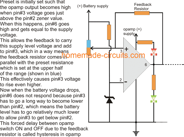
Please refer to the above example figure for understanding how the feedback resistor works in an Opamp circuit
I am sure you know about how voltage dividers work? As soon as the full
charge threshold is detected, as per the adjustment of pin#3 preset the voltage at pin#3 becomes just higher than pin#2 zener voltage, this forces the opamp output to swing to the supply level from its previous zero volt....meaning it changes from say 0 to 14V instantly.
In this situation we can assume now that the feedback is connected between "positive supply" and pin#3...when this happens the feedback resistor starts supplying this 14V to pin#3, which means it further reinforces the preset voltage and adds some extra volts depending upon its resistance value, technically this means this feedback becomes in parallel with preset resistor which is set between its center arm and the positive arm.
So suppose during the transition pin#3 was 4.8V and this switched the output to the supply level and allowed the supply to reach back to pin#3 through the feedback resistor, which caused the pin#3 to a bit more higher say at 5V....due to this pin#3 voltage will take longer to get back to below the 4.7V zener value level because it has been raised to 5V...this is called hysteresis.
Both LEDs will never light up because their junction is connected with pin#6 of the opamp which will either at 0V or the supply volt which will make sure that either the red LED lights up or the green, but never together.
What is Hysteresis
Question
Thank you for answering all my questions, especially the one about the feedback, that seems a bit advanced config so its new for me would this low voltage set point circuit option work as well; 14 volts on the non invert, 12 volt zener on the invert reference pin.
Once the 14 VDC rail dropped to 12, the opamp output trips on. This would activate the low voltage part of the circuit. In your case, the 10k pot is just "adjusting", "dividing" or bringing the 14volt rail to a voltage closer to the 4.7zener?Your still controlling the 14 VDC.
I mean once it goes to 11 VDC etc, you want a ratio that will swing the opamp high. if you replaced the 4.7 with another zener value, the pot divider would set up a new ratio, but the pot is still "following" or in ratio with the rail 14 VDC? Instead of putting 14VDC on one opamp pin, your dropping it through a divider, but the ratio is still controlling a small drop from say 14VDC to 11 VDC through the 10K pot, that will drop to 4.7V?
I'm just trying to understand how the circuit closes the "spread" from 11VDC (where we want the low voltage set point to be) and the ref voltage of 4.7 vdc. most of the comparator circuits Ive seen just have the ref vdc at pin 2, for example 6 VDC. and a rail voltage of say 12 VDC. Then a pot sets up a divider from that rail of 12VDC, drops to say 6 VDC through the mid point of the divider. Once the voltage at pin 3 approaches the ref 6 VDC @ pin 2, the opamp swings according to its config, (invert or non-invert)
Perhaps where I'm messing up is here- in other circuits I've looked at, the rail voltage is assumed to be stiff, but in this case, its going to drop Its that drop (14VDC to 11VDC) upsets the 10K voltage divider ratio?
And your using that ratio to reference the 4.7 zener? so if you have the 10K pot at its mid position of 5 k, that divider would set the 14VDC at 7 VDC (R2/R1+R2) if the 14 rail went to 11 VDC, the divider mid position is now 5.5, so it depends on where the wiper is at, am I starting to get it?
We just adjust the wiper until the 4.7 is in ratio to the voltage divider and the rail drop we want?
so this circuit is using regular opamp comparator principles, but with the added affect of hystersis for the low voltage set point control?
My Reply
Yes you are getting it right.
A 12V zener would also work, but that would cause the opamp to switch between 12V and 12.2V, the feedaback system allows the opamp to switch between 11V and 14.V, that's the main advantage of using a feedback hysteresis resistor.
Similarly in my case, if the feedback resistor was removed, the opamp would start oscillating frequently between the 14.4V cut-off level and the 14.2V reverting level. because as per the setting of the 10K preset the opamp would cut off at 14.4V and as soon as the battery voltage dropped by a few milli-volts the opamp would again switch OFF, and this would go on continuously causing a constant ON/OFF switching of the relay.
However the above situation would be fine if a relay was not used rather a transistor was used.
Question
Normally what I see in comparators is a fixed voltage like you have @ pin 2, usually through a voltage divider or zener etc, then at pin 3 a variable voltage from source - pot - ground config with wiper (pot) in the middle and the wiper will find the set point of pin 2.
In your case 4.7 fixed zener voltage and swing the opamp approx to its rails, according to its config where its confusing is that the 10K wiper in your circuit is set at 14.4 volts? Then that is supposed to trip the 4.7 zener? I don't get the match up?
How to Setup the Threshold Trip Points
My Reply
we first set the upper threshold cut off through the pot by supplying 14.4V from a variable power supply with feedback resistor disconnected.
once the above is set, we connect a correctly selected hysteresis resistor in the slot, and then begin reducing the voltage until we find the opamp switching off at the desired lower say 11V.
this sets up the circuit perfectly.
NOW, before confirming this practically we make sure that the battery is first connected and then the power is switched ON.
this is important so that the power supply is able to get dragged down by the battery level and begin with a level that's exactly equal to the battery discharge level.
that's all, after this it's all smooth sailing with the opamp following the cut off pattern as set by the user.
another important thing is that, the power supply current must be around 1/10th of the battery AH so that the power supply is able to get easily pulled down by the battery level initially.
Question
Yes I was thinking it over and without the hysteresis it wouldn't work. If I put a 7 zener at pin 2 , set Vin @ pin 3 through a 5k voltage divider to be 7 volts, and a discharged battery on the circuit, as soon as the battery got charged to 14 volts, the relay would drop in and pull in the load, but the load would drop the 7 at the pot down immediately, so the relay would drop out. Without the hysteresis, I can see now why I wouldn't work, thanks
My Reply
Even without a load the battery will never cling to the 14.4V limit and will instantly try to settle down to around 12.9V or 13V.
When opamp o/p swings to (+) it becomes as good as the supply rail, which implies that the feedback resistor gets linked with the supply rail, that further implies that pin#3 is subjected to a separate parallel voltage in addition to the presets upper section resistance which is connected with the supply rail.
This added voltage from the feedback causes the pin#3 to rise from 4.7V to say 5V...this changes the calculation for the pin3/2 and forces the opamp to stay latched until the 5V has dropped below 4.7v, which happens only when the battery voltage has dropped way down to 11V....without this the opamp would have toggled continuously between 14.4V and 14.2V
What's Full Charging Voltage and Hysteresis
The following discussion tells us regarding what's full charge voltage for lead acid batteries and hysteresis significance in battery charging systems. The questions were asked by Mr. Girish
Discussing Battery Charging Parameters
I have couple of questions which makes me scratch my head:
1) What is the full battery voltage for a standard Lead-Acid battery, at what voltage the battery need to cut-off from the charger. What must be the float charge voltage for a lead acid battery.
2) Is hysteresis resistor is crucial in comparator circuit? without it will it work properly? I've googled and found many confusing answers. I hope you can answer. Projects are on the way.
Regards.
Full Charge Cut-off and Hysteresis
Hi Girish,
1) For a 12V lead acid battery the full charge from the power supply is 14.3V (cut-off limit), float charge can be the lowest amount of current at this voltage which prevents the battery from self-discharging, and also prevents the battery from over-charging.
As a rule of thumb this current could be around Ah/70, that is 50 to 100 times less than the AH rating of the battery.
Hysteresis is required in opamps to prevent them from producing a fluctuating output (ON/OFF) in response to a fluctuating input which is being monitored by the opamp.
For example if an opamp without a hysteresis feature is configured to monitor an over charge situation in a battery charging system, then at full charge level as soon as it cuts off the charging supply to the battery, the battery will show the tendency to drop its voltage and attempt to settle down to some lower voltage position.
You can compare it to pumping air inside a tube, as long as pumping pressure is there the air inside the tube holds, but as soon the pumping is stopped the tube begins slowly deflating…same happens with the battery.
When this happens the opamp input reference reverts, and its output is prompted to switch ON the charging again, which yet again pushes the battery voltage towards the higher cut off threshold, and the cycle keeps repeating……. this action creates a rapid switching of the opamp output at the full charge threshold. This condition is usually not recommended in any opamp controlled comparator system and this might gives rise to relay chattering.
To prevent this, we add a hysteresis resistor across the output pin and the sensing pin of the opamp, so that at the cut-off limit the opamp shuts off its output and latches on in that position, and unless and until the sensing feed input has truly dropped to an unsafe lower limit (wherein the oamp hysteresis is unable to hold the latch), the opamp then switches ON again.
Download the Original Content Here:
https://www.homemade-circuits.com/wp-content/uploads/2021/03/op-amp-hysteresis-calculations.pdf
If you have more doubts regarding full charge voltage for lead acid batteries and hysteresis significance in battery charging systems, do not hesitate to put them out through comments.

Hi, thank you for the great work, but I am puzzled at figure_4 Vout voltages, could you please confirm once again?
Hi, thanks, the figure 4 looks OK to me, nothing’s wrong in it.
bonsoir,j’ai besoin d’aide concernant une simulation sur proteus d’ un circuit de gestion d’énergie basé sur l’utilisation d’un comparateur a hysteresis a 2 seuils positifs 1.8v et 2.5 v comportant a l’entrée un condensateur dont la tension de charge et de décharge sera comparé a ces deux seuils et contrôlera a la sortie de l’ampli un interrupteur basé sur un transistor.
ce circuit est destiné a l’alimentation d’une charge résistive.
I am sorry, I am not good with proteus simulation, so it can be difficult for me to help you with the topic.
I am novice in electronics, I do not know to use all these formulas to find the value of the two resistances of hysteresis in the circuit. for two 12 V accumulators, what would be their value?
You can find a 6V example below, you can modify it for a 12V easily:
https://www.homemade-circuits.com/2017/01/universal-battery-charger-circuit.html
you should tell all your viewers how to find the resistance when in parallel
so they can use the voltage divider formula …but this is a good tutorial
Thank you, I appreciate your suggestion, will try to include the info soon…