The post narrates a simple yet highly accurate adjustable 1 to 10 minute timer circuit with display. The idea was requested by one of the dedicated readers of this blog.
Technical Specifications
I am trying to build a circuit to help me with giving speeches. I have a bunch of parts already and I would like to use them if possible. I want it to have an On/Off switch to power the circuit and a Start/Stop button as well as a Reset button.
I would like for it to light a Green LED after 5 mins, then turn off the green LED and light an Amber LED at 6 mins, and then turn off the Amber LED and light a Red LED as well as sound a buzzer at 7 mins.
I would also like to have a seven-segment display show the elapsed time. Let me know haw feasible this would be. Thanks.
The Design
In the shown 1 to 10 minute timer with display circuit, IC 4060 is configured as a 1 minute clock generator which is acquired at its pin#3.
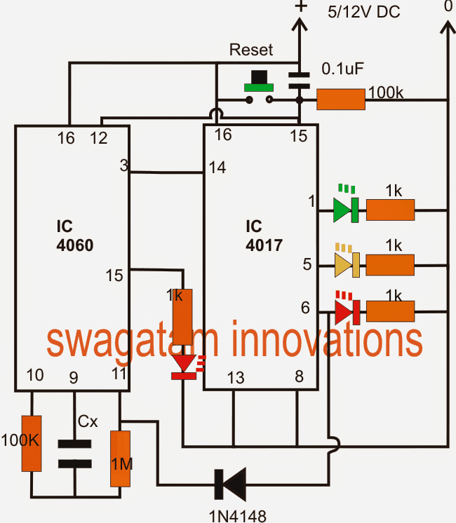
The IC 4017 is wired in its ususal decade counter mode wherein its outputs shift a logic "high" across its pin3 to pin6 in response to every single minute pulse by the IC 4060 at its pin#14.
As requested three LEDs are positioned for indicating the elapsing of 5 minutes, 6 minutes and 7 minutes in sequence across the pin1,5,6 respectively, with the relevant selected colored LEDs.
For setting up the IC 4060 with 1 minute intervl at its pin3, we initially use a randomly selected low value capacitor for Cx and then note down the interval at pin3 for this capacitor.
Once the interval is known, the value of Cx for achieving 1 minute time may be calculated with the following formula:
Cx/Cr = 1/Rm
where Cx = required value, Cr = random value capacitor (in uF), Rm = time interval noted from Cr (in seconds)
The reset button at pin15/12 of the ICs can be used for resetting the circuit to original state.
Once the final selected interval is elapsed, the circuit latches itself and freezes by supplying a "high" from the relevant IC 4017 output to pin11 of IC 4060.
The red LED at pin15 of 4060 IC indicates the counting process by blinking the connected LED until the pin#6 of IC 4017 goes high.
The proposed circuit can be used for indicating any time interval from 1 to 10 minutes by using all the outputs of the IC 4017.
For getting different ranges of time intervals across each pinout of the IC 4017, the IC 4060 clock can be set with the desired time ranges, for example 2 minutes, 5 minutes, 40 seconds etc.
This 1 to 10 minute timer circuit when used along with a 7 segment display circuit as illustrated below could consume around 60mA current so probably a ac/dc adapter would be more preferable than a battery.
Adding a 7 segment display to the above circuit
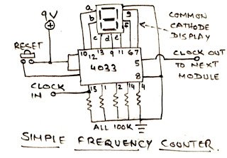
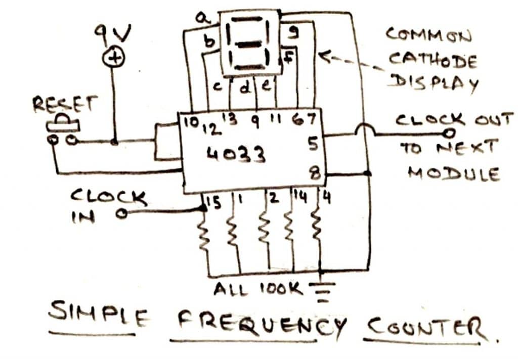
A simple pulse counter circuit using the IC 4033 shown below can be used with the above circuit for displaying the elapsed minutes.
The clock IN pin should be connected with pin3 of IC 4060.
The circuit will faithfully display the elapsed time in minutes right from 1 to the last selected minute output.
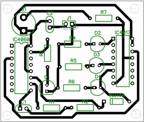
PCB Layout
1 to 10 minute timer using just two transistors
The above designs look unnecessarily complex. Because the same application can be efficiently implemented through a 2 transistor circuit as shown below:
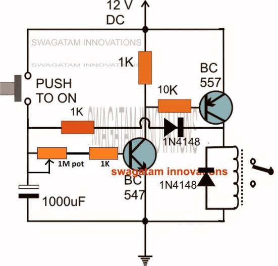
When I initially designed this, it was without the 1K/1N4148 feedback link, which actually made the design rather inaccurate with its timing cycles.
This was because of the inconsistent discharging of the 1000uF capacitor which caused inaccurate timing outputs for each subsequent timing cycles.
I realized the issue and solved it by adding the 1K/1N4148 feedback link across the BC557 collector and the 1000uF capacitor positive pin.
This ensured after each timing cycle when the BC557 switched OFF allowed the capacitor's residual charge to completely discharge via the 1K/1N4148 link and the relay coil.
This in turn allowed perfect accuracy for the capacitor charge/discharge cycles and produced uniform, consistent timing intervals for each subsequent cycles.
Simple 10 Minute Timer using an FET
The below shown 10 minute simple timer is a form of enhanced Schmitt trigger, using a combination of an FET and a BJT.
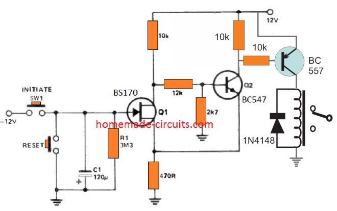
In the stand-by powered mode, the FET Q1 is in the switched ON condition, the BJT Q2 remains switch OFF, and the relay will be deactivated in its N/C position.
As soon as the timer is initiated by pressing the "initiate" switch, the capacitor C1 begins charging rapidly with the -12 V, which cuts off the FET and switches ON the BJT.
Now, when S1 is released, C1 begins slowly discharging through R1, until the potential across C1 drops to Vp of the FET.
At this instant Q1 turns ON again, and Q2 BJT turns OFF, reverting to its original standby state. The relay now deactivates again
Much longer delays can be achieved by selecting an FET with lower Vp than 1.5 V, and higher values of C1.
The only drawback of the design s that, it works with a dual supply voltage.
