
In the earlier post I have explained comprehensively about how a unijunction transistor works, in this post I will elucidate a few interesting application circuits using this amazing device called UJT.
The example application circuits using UJT which are explained in the article are:
- Pulse generator
- Sawtooth generator
- Free running multivibrator
- Monostable Multivibrator
- General purpose oscillator
- Simple crystal oscillator
- Transmitter RF Strength Detector
- Metronome
- Doorbell for 4 entrances
- LED Flasher
1) Square Wave Pulse Generator
The first design below demonstrates a simple pulse generator circuit made up of a UJT oscillator (such as 2N2420, Q1) and a silicon bipolar output transistor (such as BC547, Q2).
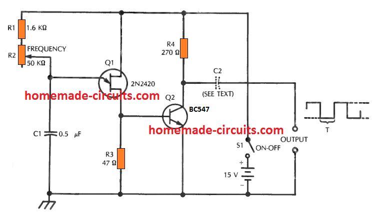
The UJT output voltage, obtained over the 47 ohm resistor R3, switches the bipolar transistor between a couple of thresholds: saturation and cutoff, generating horizontal-topped output pulses.
Depending on the off time (t) of the pulse, the output waveform could be sometimes narrow rectangular pulses or (as indicated across the output terminals in Fig. 7-2) a square wave.
The maximum amplitude of the output signal can be up to the supply level, that is +15 volts.
The frequency, or cycling frequency, is determined by the adjustment of a 50 k pot resistance and the capacitor value of C1. When the resistance is maximum with R1 + R2 = 51.6 k and with C1 = 0.5 µF, the frequency f is = 47.2 Hz, and the time off (t) = 21.2 ms.
When resistance setting is at minimum, probably with only R1 at 1.6 k the frequency will be, f = 1522 Hz, and t = 0.66 ms.
To get additional frequency ranges, R1, R2, or C1 or each one of these could be modified and the frequency calculated using the following formula:
t = 0.821 (R1 + R2) C1
Where t is in seconds, R1 and R2 in ohms, and Cl in farads, and f = 1/t
The circuit works with just 20 mA from the 15 Vdc source, although this range could be different for different UJTs and bipolars.
The dc output coupling can be seen in schematic, but ac coupling could be configured by placing a capacitor C2 within the high output lead, as demonstrated through the dotted image.
The capacitance of this unit must be approximately between 0.1µF and 1µF, the most effective magnitude might be the one which brings about minimum distortion of the output waveform, when the generator is run through a specific ideal load system.
2) Accurate Sawtooth Generator
A basic sawtooth generator featuring pointed spikes is advantageous in a number of apps involved with timing, synchronizing, sweeping, and so forth. UJTs produce this kind of waveforms using straightforward and cheap circuits.
The schematic below displays one of these circuits which, even though not a precision piece of equipment, will deliver a decent outcome in small price range labs.
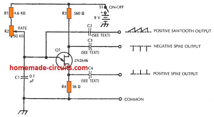
This circuit is primarily a relaxation oscillator, with outputs extracted from the emitter and the two bases. The 2N2646 UJT is hooked up in the typical oscillator circuit for these types of units.
The frequency, or repetition rate, is determined from the setting up of the frequency control potentiometer, R2.
Any time this pot is defined to its highest resistance level, the sum of the series resistance with the timing capacitor C1 becomes the total of the pot resistance and the limiting resistance, R1 (which is, 54.6 k).
This causes a frequency of around 219 Hz. If R2 is defined to its minimum value, the resulting resistance essentially represents the value of resistor R1, or 5.6 k, producing a frequency of around 2175 Hz.
Additional frequency ranges and tuning thresholds could be implemented simply by altering R1, R2, C1 values, or may be all the three together.
A positive spiked output can be acquired coming from base 1 of the UJT, while a negative spiked output through base 2, and a positive sawtooth waveform through the UJT emitter.
Although dc output coupling is revealed in Fig. 7-3, ac coupling could be determined by applying capacitors C2, C3, and C4 in the output terminals, as demonstrated through the dotted area.
These capacitances will probably be between 0.1 and 10µF, the value determined being based on the highest capacitance which may be tackled by a specified load device without distorting the output waveform.
The circuit operates using around 1.4 mA through the 9 volt dc supply. Each of the resistors are rated at 1/2 watt.
3) Free -Running Multivlbrator
The UJT circuit proven in the below shown diagram resembles the relaxation oscillator circuits explained in the a couple of previous segments, apart from that its RC constants happen to be selected to provide quasi-square-wave output similar to that of a standard transistorized astable multivibrator.
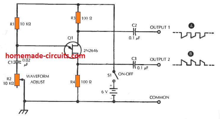
The type 2N2646 unijunction transistor works nicely inside this indicated set up. There are basically two output signals: a negative-going pulse at UJT base 2, and a positive-going pulse at base 1.
The open circuit maximum amplitude of each of these signals is around 0.56 volt, however this could deviate a bit depending on specific UJTs. The 10 k pot, R2, should be turned for acquiring a perfect tilt or horizontal topped output waveform.
This pot control additionally impacts the range of the frequency, or the duty cycle. With the magnitudes presented here for R1, R2, and C1, the frequency is around 5 kHz for a flat-topped peak.
For other frequency ranges, you may want to adjust R1 or C1 values accordingly, and use the following formula for the calculations:
f = 1/0.821 RC
where f is in Hz, R in ohms, and C in farads. The circuit consumes around 2 mA from the 6 V dc power source. All fixed resistors can be rated at 1/2 -watt.
4) One-Shot Multivibrator
Referring to the following circuit, we find a configuration of a one-shot or a monostable multivibrator.
A 2N2420 number unijunction transistor and a 2N2712 (or BC547) silicon BJT can be seen put together to generate a solitary, fixed amplitude output pulse for every single triggering at the input terminal of the circuit.
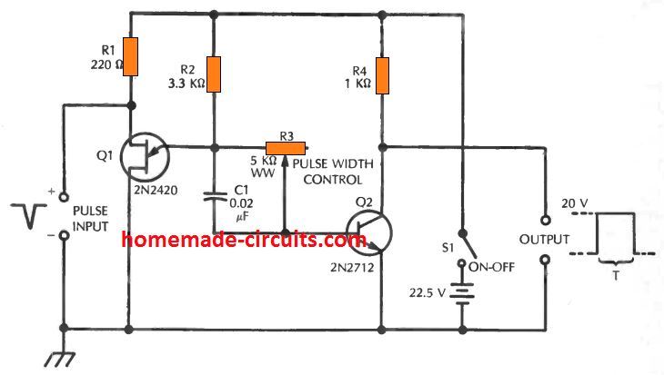
In this particular design, the capacitor C1 is charged by the voltage divider established by R2, R3, and the base-to-emitter resistance of transistor Q2, causing its Q2 side negative and its Q1 side positive.
This resistive divider additionally supplies the Q1 emitter with a positive voltage which is slightly smaller than the peak voltage of the 2N2420 (refer to point 2 in the schematic).
In the beginning, Q2 is in switched ON state; which causes a voltage drop across resistor R4, decreasing the voltage at the output terminals drastically to 0.
When a 20 V negative pulse is given across the input terminals, Q1 "fires," causing an instant drop of voltage to zero at the emitter side of C1, which in turn biases the Q2 base negative.
Due to this, Q1 gets cut off, and the Q1 collector voltage increases swiftly to +20 volts (notice the pulse indicated across the output terminals in the diagram).
The voltage continues to be around this level for an interval t, equivalent to the discharging time of capacitor C1 via the resistor R3. The output subsequently drops back to zero, and the circuit goes into stand by position until the next pulse is applied.
Time interval t, and the correspondingly the pulse width (time) of the output pulse, rely on the adjustment of the pulse width control with R3.
As per the indicated values of R3 and C1, the time interval range can be anywhere between 2 µs to 0.1 ms.
Supposing that R3 encompasses the resistance range between 100 to 5000 ohms. Additional delay ranges could be fixed by appropriately modifying the values of C1, R3, or both, and using the formula: t = R3C1 where t is in seconds, R3 in ohms, and C1 in farads.
The circuit operates using roughly 11 mA through the 22.5 V dc supply.
However this could be likely to change to some extent depending on the UJTs and bipolars types. All fixed resistors are 1/2 watt.
5) Relaxation Oscillator
A simple relaxation oscillator offers numerous applications widely recognized by most electronics hobbyists.
The unijunction transistor is a remarkably tough and reliable active component applicable in this kind of oscillators.
The schematic below exhibits the fundamental UJT relaxation oscillator circuit, working with a type 2N2646 UJT device.
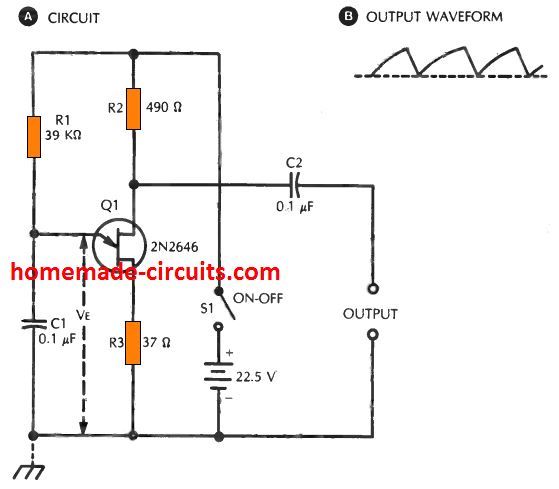
The output is actually somewhat curved sawtooth wave consisting of peak amplitude roughly corresponding to the supply voltage (which is, 22.5 V here).
In this design, current travelling through the dc source via resistor R1 charges capacitor C1. A potential difference VEE as a result steadily accumulates across C1.
The moment this potential reaches the peak voltage of the 2N2646 (see point 2 in Fig. 7-1 B), the UJT turns ON and "fires."
This immediately discharges the capacitor, switching OFF the UJT back again. Th is causes the capacitor to initiate the recharge process again, and the cycle simply keeps repeating.
Due to this charging and discharging of the capacitor the UJT switches on and off with a frequency established through the values of R1 and C1 (with the values indicated in diagram, the frequency is around f = 312 Hz).
To achieve some other frequency, use the formula: f =1/(0.821 R1 C1)
where f is in Hz, R1 in ohms, and C1 in farads. A potentiometer with an appropriate resistance could be used in place of the fixed resistor, R1. This will enable the user to achieve a continuously adjustable frequency output.
All resistors are 1/2 watt. Capacitors C1 and C2 may be rated at 10 V or 16 V; preferably a tantalum. The circuit consumes roughly 6 mA from the indicated supply range.
6) Spot Frequency Generator
The following configuration indicates a 100 kHz crystal oscillator circuit which could be used in any standard method like a alternative standard frequency or spot frequency generator.
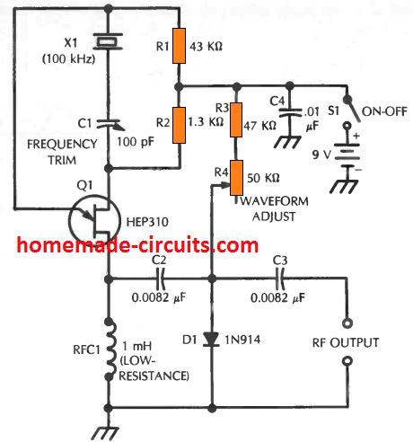
This design produces a deformed output wave which can be highly suitable in a frequency standard so that you can guarantee solid harmonics loaded with the rf spectrum.
The joint working of the unijunction transistor and the 1N914 diode harmonic generator generates the intended distorted waveform.
In this set up, a tiny 100 pF variable capacitor, C1, enables the frequency of the 100 kHz crystal to be adjusted a bit, to deliver an increased harmonic, for example 5 MHz, to zero beat with a WWV/WWVH standard frequency signal.
The output signal is produced over the 1 mH rf choke (RFC1) which is supposed to have a lower dc resistance.
This signal is given to the 1N914 diode (D1) which is dc biased by means of R3 and R4 to achieve a maximum non-linear portion of its forward conduction characteristic, to additionally distort the output waveform from the UJT.
While using this oscillator, the variable waveform pot, R3, is fixed for achieving the most powerful transmission with the proposed harmonic of 100 kHz.
Resistor R3 acts simply like a current limiter to stop direct application of the 9 volt supply across the diode.
The oscillator consumes around 2.5 mA from the 9 Vdc supply, but, this could change relatively depending on specific UJTs.
Capacitor C1 should be a midget air type; the remaining other capacitors are mica or silvered mica. All fixed resistors are rated at 1 watt.
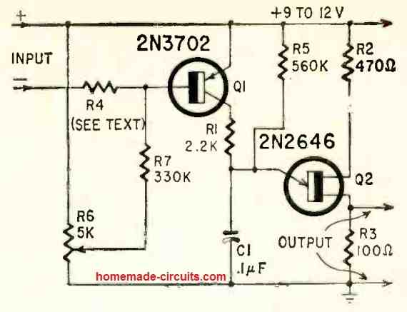
7) Transmitter RF Detector
The RF detector circuit demonstrated in the following diagram can be powered directly from rf waves of a transmitter which is being measured.
It provides a variable tuned sound frequency into an attached high impedance headphones.
The sound level of this sound output is determined by the energy of the rf, but could be just sufficient even with low powered transmitters.
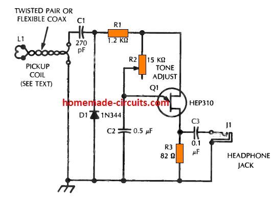
The output signal is sampled through L1 rf pickup coil, consisting of 2 or 3 winding of insulated hookup wire fitted firmly close to the transmitter's output tank coil.
The rf voltage is converted to DC through a shunt-diode circuit, made up of blocking capacitor C1, diode D1, and filter resistor R1.
The resultant rectified dc is utilized to switch the unijunction transistor in a relaxation oscillator circuit.
The output from this oscillator is fed into an attached high impedance headphones via coupling capacitor C3 and output jack J1.
The signal tone as picked up in the headphones could be altered across a decent range through the pot R2.
The frequency of the tone will be somewhere around 162 Hz when R2 is adjusted to 15 k. Alternatively, the frequency will be roughly 2436 Hz when R2 is defined to 1 k.
The audio level could be manipulated by rotating L1 closer to or away from the transmitter LC tank network; typically, a spot will likely be identified that provides reasonable volume for most basic usage.
The circuit can be constructed inside a compact, earthed metallic container.
Usually, this could be positioned at some fair distance from the transmitter, when a decent quality twisted pair or flexible coaxial cable is employed and when L1 is connected to the lower terminal of the tank coil.
All fixed resistors are rated at 1/2 watt.
Capacitor C1 must be graded to tolerate the highest dc voltage which could inadvertently be experienced in the circuit; C2 and C3, on the other hand, could be any practical low voltage devices.
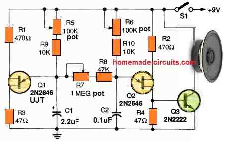
8) Metronome Circuit
The set up given below exhibits a completely electronic metronome using a 2N2646 unijunction transistor.
A metronome is a very handy little device for many music artists and others who look for an evenly timed audible notes during music composition or singing.
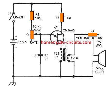
Driving a 21/2 inch loudspeaker, this circuit comes with a decent, high in volume, pop like sound.
The metronome could be created pretty compact, the speaker and battery audio outputs are the only its largest sized elements, and, since it's battery powered, and therefore is entirely portable.
The circuit is actually an adjustable frequency relaxation oscillator which is paired through a transformer to the 4 ohm speaker.
The beat rate can be varied from roughly 1 per second (60 per minute) to around 10 per second (600 per minute) using a 10 k wirewound pot, R2.
The sound output level can be modified through a 1 k, 5 watt, wirewound pot, R4. The output transformer T1 is actually a small 125:3.2 ohm unit.
The circuit pulls 4 mA for the minimum beat rate of the metronome and 7 mA during the fastest beat rate, although this could fluctuate depending on specific UJTs.
A 24 V battery will offer excellent service with this reduced current drain.
Electrolytic capacitor C1 is rated at 50 V. Resistors R1 and R3 are 1/2 watt, and potentiometers R2 and R4 are wirewound types.
9) Tone Based Signalling System
The circuit diagram shown below makes it possible for a independent audio signal to be extracted from each of the indicated channels.
These channels may possibly include unique doors inside a building, various tables within an workplace, various rooms within a house, or any other areas where push buttons could be worked with.
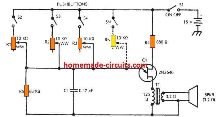
The location which might be signaling the audio could be identified by its specific tone frequency.
But this may be feasible only when a lower number of channels are employed and that the tone frequencies are significantly wide apart (for example, 400 Hz and 1000 Hz) so that they are easily distinguishable by our ear.
The circuit again is based on a simple relaxation oscillator concept, using a type 2N2646 unijunction transistor to generate the audio note and commute a loudspeaker.
The tone frequency is defined through capacitor C1 and one of the 10 k wirewound pots (R1 to Rn).
As soon as the potentiometer is set to 10k ohms, the frequency is around 259 Hz; when the pot is set to 1k, the frequency is roughly 2591 Hz.
The oscillator is connected with the speaker via an output transformer T1, a tiny 125:3.2 ohm unit with primary side center tap unconnected. The circuit works with somewhere around 9 mA from the 15 V supply.
10) LED Flasher
A very simple LED flasher or LED blinker could be built using an ordinary UJT based relaxation oscillator circuit as shown below.
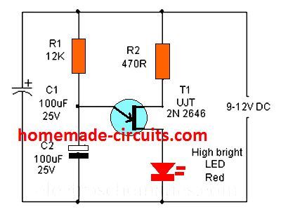
The working of the LED flasher is very basic. The blinking rate is determined by the R1, C2 elements. When power is applied, the capacitor C2 slowly begins charging via the resistor R1.
As soon as the voltage level across the capacitor exceeds the firing threshold of the UJT, it fires and switches ON the LED brightly.
The capacitor C2 is now begins discharging through the LED, until the potential across Cr drops below the holding threshold of the UJT, which shuts off, switching OFF the LED.
This cycle keeps repeating, causing the LED to flash alternately.
The LED brightness level is decided by R2, whose value could be calculated using the following formula:
R2 = Supply V - LED Forward V / LED Current
12 - 3.3 / .02 = 435 Ohms, so 470 ohms seems to be the correct value for the proposed design.
Incandescent Lamp Flasher
Quite similar to the above concept, the following UJT circuit is able to flash a high power incandescent lamp.
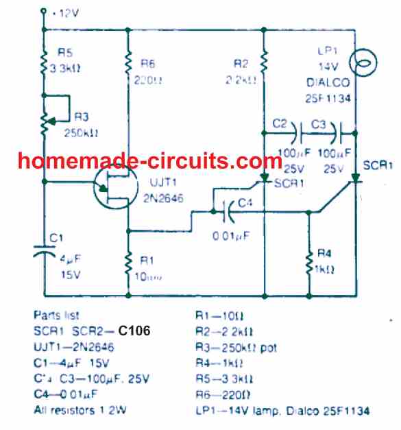
It uses SCRs for the operations. The bulb could be also replaced with high power LEDs
Toy Siren Circuit
This circuit is so small small that it can be easily fitted inside any desired toy.
With a bit of skill by the user, the toy siren circuit can be tailored to sound like the ambulance siren or other form of emergency sirens.
The transducer used is can be an earphone or a piezo transducer.
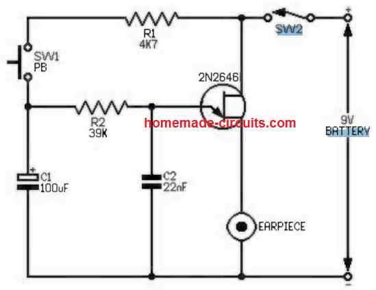
The circuit works like a relaxation oscillator using a single unijunction transistor (2N2646, MU10, TIS43).
R2 and a capacitor C2 decide the frequency of the siren tone.
When button SW1 is pushed it enables capacitor C1 to charge up causing the R2, C2 junction voltage to rise which induces an upward shooting frequency of oscillation.
Now as soon as the the push-button is released the charge inside C2 begins dropping gradually causing a proportionate slow decrease in the frequency of oscillation.
If the push button is switched ON/OFF, with a time interval of around 2 sec between ON OFF enables the circuit to generate a siren like sound.
High Volume Siren
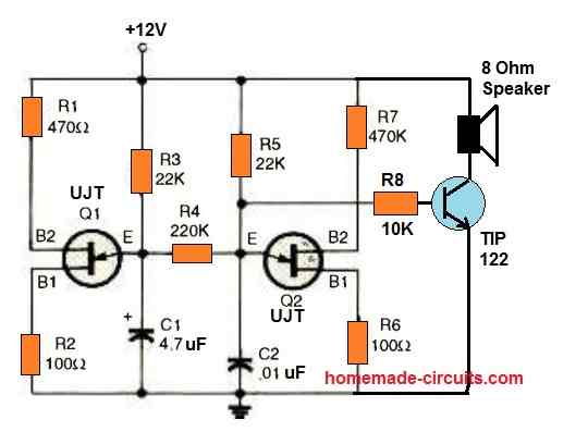
This siren circuit might be useful if you want to frighten away attackers or just experiment with loud devices.
Sawtooth oscillators are created using UJT transistors Q1 and Q2. Q1 is responsible for low-frequency modulation, and Q2 works like the tone generator.
This circuit is a great illustration of the way an RC constant allows a circuit control.
Single UJT Tone Generator Oscillator Circuit
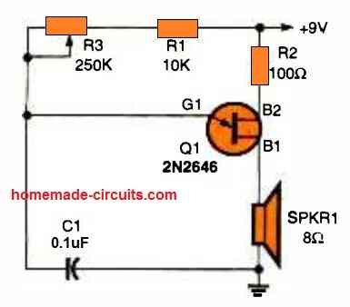
The simplest UJT oscillator, tone generator operates as follows.
C1 charges via R1 and R3 after the circuit is powered.
The dynamic resistance between the B2 and B1 decreases to an extremely minimal value as soon as the voltage exceeds the UJT gate's (G) threshold voltage.
This threshold is typically between 0.5 and 0.8 volts.
After that, the capacitor discharges via the emitter base junction and the 8-ohm speaker.
The settings of Cl, R1, and R3 dictate the frequency of the UJT oscillator. Lowering the oscillator's frequency may be achieved by increasing either the value of the capacitor or the resistor.
Miscellaneous Circuits
There are actually plenty of miscellaneous circuit ideas which can be configured using UJTs. Here I have explained a few more UJT based circuits which can be a lot of fun to build and test.
Simple Electronic Organ using UJT
The following circuit shows a simple electronic organ circuit using a single UJT and a few other passive electronic components.
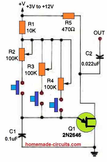
A basic UJT based oscillator has been created in this design having 3 separate pots for adjusting 3 tone output ranges.
When the relevant push buttons are pressed, different musical tones are generated through the speaker depending on the settings of the individual pots.
More number of such pot and button combination could be added in parallel to the existing set up for getting more ranges of adjustable tone outputs.
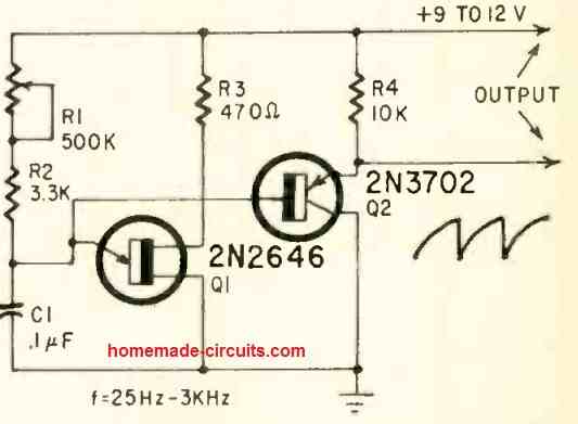
Large Amplitude Pulse Generator
The UJT pulse generator shown below produces a huge amplitude, negative-going pulse over R4, and a positive-going pulse over R3.
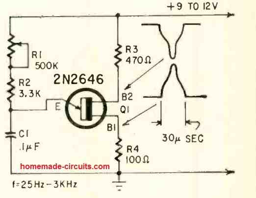
Each pulses include a voltage amplitude of approximately 50 % of the supply voltage, both are of identical type, and are both low impedance.
The R4 pulse is appropriate for triggering an SCR. Using the part values indicated in the figure, the pulse width will be consistent at around 30 sec on the frequency range between 25 to 3000 Hz (which can be adjusted using R1).
The pulse width and frequency range could be changed simply by changing the C1 value.
If C1 value is decreased by 10 (to 0.01 uF), this will lower the pulse width with an factor of 10 (to around 3 µsec) and increases the frequency range with a decade (250 Hz to 30 kHz) . C1 could be anywhere between 100 pF to 1000 uF.
A sawtooth waveform is created on the emitter, however reaches an extremely large impedance value and is therefore not easily obtainable externally.
Wide Range Sawtooth Generator
In the following UJT application circuit, the saw-tooth waveform from the Q1 emitter is applied to emitter follower Q2.
Consequently the sawtooth presents itself on the Q2 emitter at an impedance of approximately 10,000 ohms.
Output coupling could be created, both directly or through a coupling capacitor, to an outside load of 10,000 ohms or higher, with no negative consequences on the waveform or the running frequency.
Frequency range is approximately 20 to 3000 Hz using the indicated part values.
Therefore the range will be higher than 100 to 1 by means of R1. In case a scaled-down range is necessary, decrease the R1 value.
Running frequency could be adjusted from below a single cycle per minute (0.017 Hz) to more than 100 kHz by ideal selection of C1.
When an output impedance less than 10,000 ohms is desirable, you can connect another emitter follower having an emitter load of 2700 ohms on the emitter of Q2.
Temperature, Light Dependent Frequency
The next circuit below transforms variations in ambient light level, temperature or some other parameter which could be produced through a varying resistance, into variations in frequency.
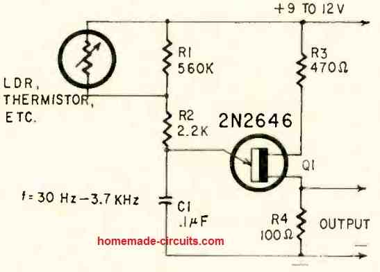
The resistive component (LDR, thermistor, etc.) is hooked up in parallel with R1, and thus regulates the C1 charging time constant, thereby the running frequency of the circuit.
A frequency range of 30 Hz to 3,700 kHz can be obtained. The lower frequency could be acquired using an open circuit for the variable resistor parameter.
Output can be obtained around R4, which generates a series of pulses.
If this output applied across a headphone, the frequency could he clearly listened to, even while the frequency is at a minimum level.
The design can be specifically useful in remote reading of things like temperature, which allows the output pulses to regulate a radio or related device.
Shunt Type Analogue to Digital Converter
In the below shown shunt type analogue to digital converter UJT circuit, the running frequencies tend to be governed by voltage or by any kind of parameters which could be produced through a voltage source such as from a photovoltiac cells, thermocouples, etc.
This circuit is actually basic shunt -controlled converter.
Transistor Q1 shunts the primary timing capacitor (C1) and thus shunts off some level of its charging current which consequently influences the working frequency of the UJT output.
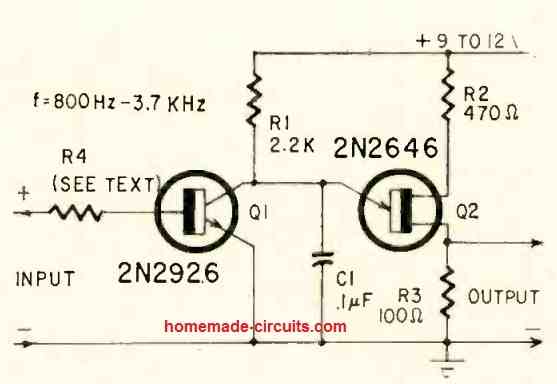
In case no voltage is applied to the base of Q1, it gets cut off, which causes the circuit to operate with a maximum frequency of approximately 3.7 kHz.
While a positive voltage is applied to the base of Q1, it is triggered on and the working frequency drops.
A limitation in this UJT circuit is that, as Q1 is turned ON, there is a drop in the collector voltage of Q1's collector voltage; and while it drops to below Vr, the circuit simply stops working.
The frequency range of the unit is as a result somewhat limited, approximately to 800 Hz to be the least in this scenario.
The R4 value can be selected, by experimentation, to match up the control voltage being used.
Typically, it may have a value of several thousand kilo ohms with input signal voltages of approximately around 10 volts, and some megohms if the input signal is at 100 volts.
Series Type Analogue to Digital Converter
The next UJT application circuit displays a fundamental series regulated converter. In this design, the charging current of C1 is governed practically fully by Q1.
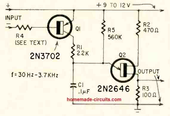
As soon as Q1 is pushed hard on (saturated) with an input signal fed to R4, the C1 charging current is restricted through R1, which causes the circuit to operate at approximately 3.7 kHz.
As soon as a zero signal voltage is fed to R4 base, Q1 gets switched off, so that capacitor C1 is able to charge through R5, producing an running frequency of approximately 30 Hz.
Between both of these extremes, the frequency could be effortlessly regulated by the voltage supplied to the base of R4 (which regulates the Q1's collector current).
Just like the previous circuit, the value of R4 is identified through some experimentation.
Improved Analogue to Digital UJT Converter
In both the above analogue to digital UJT converter circuits, transistor Q1 remains turned off until a forward voltage of about 0.6 is attached to its base.
Due to this reason the operating frequency of the circuit cannot be controlled through voltages lower than this 0.6V value.
This particular problem could be eliminated by making use of a standing bias to Q1 base, as revealed in the above shown improved design.
This customization enables utilization of input voltages straight down to zero, as well as reverse voltages. R4 can be yet again found fixed with some trial and error. Values of many 100K will do the job nicely.
Wailing Witch Sound Effect Generator
The next UJT application circuit we'll look at is an electronic "wailing witch." Feel free to give the circuit whatever name you choose; after using it for a while, you could discover a better one.
Whatever name you give it, this is how the circuit functions.
UJTs Q1 and Q2 are coupled in a dual oscillator circuit, which includes two unijunction transistors.
With the working frequency being controlled by C1, R1, R5, and R9, transistor Q1 is coupled to a extremely low frequency relaxation oscillator circuit.
Unijunction transistor Q2 is coupled in an identical oscillator circuit that runs at a significantly greater audio frequency.
The frequency of this oscillator is controlled by R6, R10, and C2.
A 1-megohm potentiometer in resistor R7 controls the mixing level of the two oscillators. R5, R7, and R6 may all be adjusted to generate a wide range of weird noises.