Building a power hi-fi amplifier with MOS transistors requires the implementation of a relatively large number of components because, at the level of power stages, the connection between the bipolar transistors that make up the input stages and the MOS transistors of the output stages is far from simple.
Fortunately, there is an elegant solution to this problem with one of the rare power amplifier integrated circuits on the market that uses MOS transistors in its output stage: the TDA7294 from ST Microelectronics.
This circuit is quite old, being over twenty years old, and has no equivalent to this day. Its performance is capable of putting many conventional amplifiers to shame.
Furthermore, its simplicity of implementation and very affordable price (around 8 euros) should encourage you to use it more often. This is what we propose to do with this article.
The amplifier that we propose to build comes in the form of a module consisting of a single mono stage.
By proceeding in this way, our assembly is adaptable to all situations since it will be sufficient for you to build two identical modules for a stereo amplifier and up to six identical modules for a home cinema amplifier.
The output power it can deliver is directly related to the impedance of the speakers used and the power supply that you apply to it.
The 60W power output is the minimum guaranteed by the manufacturer of the TDA7294.
Note that this power is an effective value since it is the only one that has a meaning, and it is indicated for a distortion lower than 0.5%.
Note the particularly low value of distortion over the entire usable output power range since, at a frequency of 1 kHz and from a few hundred mW to 60W (for an 8 ohm load chosen as an example), the distortion remains below the 0.005% line.
Even better, for the same output power range but at a frequency of 20 kHz, this distortion only rises to 0.05%, which is a remarkable performance that many discrete component amplifiers are unable to achieve!
The amplifier's bandwidth is obviously in line with these performance characteristics since it is guaranteed to be better than 20 Hz to 20 kHz at -3dB over the entire output power range.
The power supply rejection, i.e., the amplifier's ability not to reproduce the noise superimposed on the power supply voltage, generally consisting of the 100 Hz hum induced by the rectification of the sector, is guaranteed to be greater than 60 dB, with a typical value of 75 dB.
This means that no power supply hum is to be feared as long as it uses filter capacitors that are appropriate for the output power to be provided.
Finally, it should be noted that the TDA 7294 is protected against short-circuits at the output as well as against excessive heating. It automatically goes into silent mode when the chip's temperature reaches 145°C, then into standby mode if the temperature continues to increase and reaches 150°C.
Despite these remarkable characteristics, let's not be afraid to say that the circuit diagram of our amplifier remains extremely simple, as we will discover now.
Circuit Description
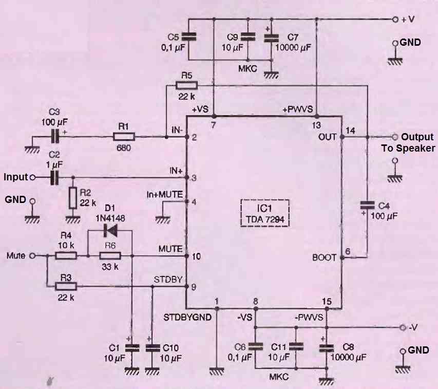
A very simple diagram is presented in its entirety in the following figure and could almost do without much explanation because it is so simple.


In fact, the TDA7294 can be likened to a "big, non-inverting operational amplifier wired in a circuit.
The gain-setting resistors R1 and R2 are recognizable, while R2 fixes the input impedance of the circuit at around 18K ohms (22k ohms in parallel with the TDA 7294's own impedance).
The circuit has four power pins, two positive and two negative, because the power stages are separated from the input stages.
A generous decoupling of these power supplies is provided by C5 and C7 on the one hand, and by C6 and C8 on the other.
As for the somewhat unusual capacitors C9 and C11, which are 10 uF but non-electrolytic, their presence was requested by audiophile friends because they heard an improvement with them.
With a power supply rejection better than 60 dB, we don't see why, but it is well known that audiophiles have reasons that reason ignores…
The TDA7294 can be used in many applications and has a silent input (mute) and a standby input. We have combined them into a single command that we have called "mute" (silence in good French).
The resistors, capacitors, and diode visible at this level are only there to ensure the correct timing of voltage application to these two inputs in order to avoid any parasitic noise.
If this "mute" input is grounded, the amplifier is in standby mode, so it is silent and consumes only a very low current (less than 3mA). On the other hand, it functions normally when "mute" is connected to the positive power supply voltage +V.
Construction
The supply of components should not pose a problem, as the TDA7294 is now available from many retailers.
Remember that capacitors C9 and C11 are optional, as we explained above.
You can choose to install them or not, depending on the instructions given by your kit and your budget.
The heatsink should be chosen according to the output power required.
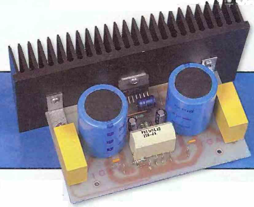
A model of around 150 x 70mm and with a thermal resistance of 1.5°C/W, like the one shown in the photo of our prototype, is a minimum if you want to benefit from all the 100 watt output power.

The solution of screwing the TDA7294 onto one side of the housing that receives the assembly is only acceptable for output powers not exceeding 20W.
Beyond that, the circuit will quickly become too hot, and the thermal protection will kick in and "cut the power" to your amplifier.
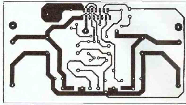
Although the TDA7294 is very stable, we recommend that you use the printed circuit board we have designed, which you will find reproduced in the figure below.

Do not decrease the width of the tracks, as there is a current flowing through them that can be quite substantial at high power levels of 100 watt.
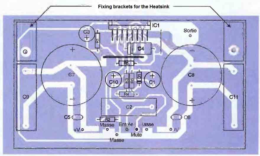
The wiring should be done as indicated in the following figure in the usual order, i.e., straps, resistors, and capacitors, ending with the diode and the integrated circuit itself.

Note that the strap corresponding to C4 must be made with 10/10mm copper wire because it carries a significant current.
Also note that if you want to use a heatsink of the same type as the one we used, fixed with the two brackets visible on either side of the printed circuit board, do not solder C2, C9, and C11 for the moment so that you can easily attach them and the TDA7294 to this heatsink.
Regarding this heatsink, it should be mentioned that the metal tab of the TDA7294 has the unfortunate tendency to be connected not to ground but to the negative of the power supply.
Therefore, you must either mount the TDA7294 on this heatsink with conventional isolation accessories such as a mica or insulating material pad and a shoulder washer for the screw, or directly mount the TDA7294 on the heatsink but then isolate the mounting from the board in which the assembly will be placed.
In both cases, the TDA7294 (and the isolation accessory in the first case) should be generously covered with silicone grease to improve the thermal contact with the heatsink.
How to Test
For listening to 100 watt power the tests cannot be conducted on a laboratory power supply table, or else you will have to do with a low output power.
Indeed, given the current absorbed on the power lines at high output power, they must be at a low impedance which is not well accommodated by a flying or temporary wiring!
In any case, you have nothing to fear because if you have made no wiring errors, which is quite unlikely given the simplicity of the circuit, operation is assured.
This power supply, precisely, must be a classic symmetrical module that will not need to be stabilized.
It must deliver ±35V at 3A if you want to operate under 8 Ohms and ±27V at 4.2A if you want to operate under 4 Ohms and benefit from the maximum available power.
These voltages are, of course, those that should be present at the output of the power supply when the amplifier is operating at full power.
However, be careful that the output voltage of an unstabilized power supply increases at low output power. It should not exceed ±40V, which is the limit value accepted by the TDA 7294.
In the first case, a 2x30V/150VA transformer followed by a 200V/5A pentode will be sufficient. In the second case, a 2x24V/150VA transformer and a 7A bridge rectifier will be needed.
Of course, these figures are valid for one module and therefore need to be increased depending on the number of modules you want to operate with the same power supply.
Given the currents involved, both the power supply and the output wiring to the speakers will be made of large diameter wire (10/10 mm diameter is the minimum).
Moreover, if your modules are far from the preamplifier responsible for controlling them, make sure to drive them at low impedance.
We have indeed noticed a very slight tendency for the TDA7294 to oscillate if it was driven by a source with too high an output impedance.
Hi, thanks for your quick response. Do you have a power circuit for the car? Thanks again.
You can try the amplifier circuit which is explained in the above article, using two two parallel 8 ohm speakers at the output.
Hello Mr. Swagatam good afternoon my name is Carlos. I have a question, I have a mono audio output, and I want a power circuit… Where 2 amplified outputs come out from one input… It’s for a car. Thank you very much in advance
Hi Carlos, you can build a single power amplifier and divide the output across two speakers.