
The discussed circuit is a solid state AC to DC voltage converter that will convert any AC input between 85 V and 250 V into a constant 310 V DC output. This kind of circuits are normally use in LCD TV sets for operating the system through inputs from 100 V AC to 250 AC.
The good thing about this circuit is that it does not depend on complex inductors and ferrite transformers as we have in SMPS circuits, rather it works with a perfectly solid-state design using only an FET, few diodes and a couple of capacitors.
How the Circuit Works
Referring to the shown circuit diagram, the working of the unit can e understood with the following points:
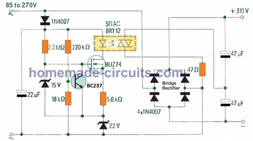
The device BRT12 remains switched OFF as long as the input AC level is between 180 V and 270 V.
In this situation the bridge rectifier using 4nos 1N4007 diodes causes a full waev rectification of the input into a 300 V DC output, across the shown couple of high voltage filter capacitors.
However if a relatively low level input such as a 110 V DC is applied, the opto-triac BRT12 switches ON, causing a low resistance connection to develp across the bridge rectifier stage and the junction of the two filter capacitors.
This situation causes the bridge rectifier to turn into a voltage doubler, which enables the output to continue to be at around 300 V DC level.
The opto-triac is operated through a basic configuration comprosong of a SIPMOS FET BUZ74. The 22V zener is used for generating a reference voltage, and the netwrok using the 1N4001 diode and the 22 pF capacitor is used like a single phase rectifier stage.
When a low 110 V AC input is used, the BJT BC237 is turned OFF via the potential developed at the junction of the 220 k, 18 k resistive divider network.
This causes the FET to switch ON through a gate potential fixed by the 15 V zener diode.
The 5k6 series resistor ensures that the current through the BRT12 and the FET drain is limited to 2 mA. This is maintained even at relatively higher input voltages up to 175 V.
When the AC input exceeds this higher level, the base potential of BC237 increases to a level which is enough to switch it ON. This in turn effectively short-circuits the FET gate to ground, shutting OFF the FET and the current through the BRT12 opto.
Basically, the circuit can operate using AC inputs right from 50 V up to 300 V AC. The changeover happens at around 165 V input, when the opto-triac device BRT12 becomes non conductive. This turn OFF is implemented by the BJT BC237 and its base potential determined by the associated resistive divider circuit.
The main components that control the output at 310 V DC are the opto-triac BRT12, the bridge rectifier and the two output capacitors.
The maximum current capacity of this 110 V to 310 V converter circuit is 200 mA with ambient temperature not exceeding 45 °C. This current is sufficient for satisfactory working of most electronic gadgets.
Parts List
Resistors 1/4 watt 1% MFR
- 2M2 - 1no
- 220k - 1no
- 18k - 1no
- 5k6 - 1no
- 47 ohms - 1no
Capacitors
- 22uF/400V electrolytic - 1no
- 47uF/400V - 2nos
Semiconductors
- Opto-Triac BRT12 - 1no
- FET BUZ74 - 1no
- BJT BC237 - 1no
- Diodes 1N4007 - 5nos
- 22V 1 watt zener - 1no
- 15V 1 watt zener - 1no
110V to 220V Booster Circuit
Several foreign nations have 110 volts mains supplies. This is often a trouble in case your electrical appliance is made for working with 220/240 volts specifically.
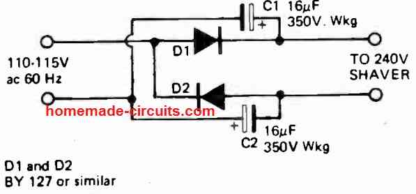
The above shown simple rectifier voltage doubler enables converting your 110V AC to 220 V DC at low current so that you can operate electrical appliances like heaters, soldering iron, electric shavers, mobile chargers etc through this circuit.
Because the output voltage is 220V dc the particular circuit can be only employed to operate little ac/dc motor or heater based equipment, or mobile chargers. It should not be utilized, for instance, to operate electronic items like radio sets, TV sets except if these are specifically ac/dc operated types.