

In this post I have explained a simple car laptop charger circuit for charging laptops from a 12V car battery using a IC 555 based boost converter. The idea was requested by one of the avid readers of this blog.
Making a 12V to 19V Converter
May I request you for a circuit diagram for a transformerless small 100w inverter which can be used with a car 12V battery to power a laptop? I've found one circuit online but as I am a very new comer to electronics, I didn't understand that. Your help will be highly appreciated. Thanks
You may also like: 12 V to 19 V Converter Circuit
The Transistor Astable Design
A classic boost converter which will perfectly suit the proposed 12 V to 24 V car laptop charger application can be quickly built using a fully transistorized design as shown below:

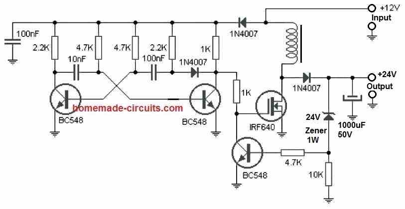
All the shown parts are standard, or could be replaced with other suitable equivalents.
The inductor which is one of main parts of the circuit is built over a ferrite rod 1 cm in diameter, by winding 100 turns of super enameled copper wire having 1 mm thickness.
Actually, the inductor is dependent on the frequency of the transistor astable. For higher frequencies the number of turns will proportionately go down, and is a matter of some experimentation. The turn number will also depend on the ferrite core shape, and may significantly decrease if a ring type ferrite core is used.
The IC 555 Design
The proposed car laptop charger circuit is actually a simply boost converter unit designed for generating the required laptop charging voltage.
A simple boost converter can be made using the IC 555, I probably have discussed it through many other posts in this blog.
As may be witnessed in the following figure, a simple yet very efficient boost converter circuit can be constructed for using with laptops from any high current source having a lower voltage than the laptop charging level.
Circuit Diagram for the Boost Converter

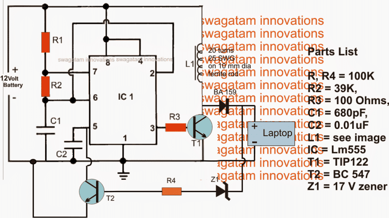
The various stages included in the above 12 V laptop boost charger circuit may be understood as follows:
IC1 which is a 555 IC is configured as a standard astable for generating a stable predetermined frequency at the rate of 12 kHz which is acquired at pin3 of the IC.
The above high frequency output is fed to the base of a driver BJT T1 for inducing the above frequency with high current in L1.
Due to the inherent property of the inductor L1, during every OFF time of T1, an equivalent amount of boosted voltage is kicked back from the inductor L1 and supplied to the load connected at the output via the fast recovery diode BA159.
The load here is the laptop which accepts the boosted voltage for charging its internal battery.
Since the laptop may require a precise 19 to 20V for the operations, the output from L1 must be regulated and stabilized in order to make things safe for the connected laptop battery.
The above criterion is taken care of by introducing T2 and the associated R4 and Z1 components.
Z1 is selected to be exactly equal to the laptop charging voltage that is at 20 V (17V is wrongly shown in the diagram).
Whenever the output tends to drift away from this value, Z1 gets forward biased triggering T2, which in turn grounds pin5 of the IC.
The above situation immediately reduces the IC 555 pin3 voltage to minimal levels for that instant until Z1 stops conducting and the situation is restored to the safe zone....the switching is sustained at a rapid speed maintaining a constant voltage for the laptop.
This car laptop charger circuit can be used for charging a laptop in any car which uses a 12V battery.
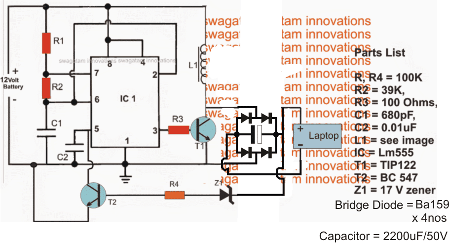
Adding a Bridge Rectifier at the Output
The above design can be much improved by employing a bridge rectifier at the output instead of a single diode, as illustrated in the following diagram:

Using MOSFET Voltage Doubler Circuit
In this post I have explained a simple circuit which may be incorporated for charging a laptop while driving in car or some other vehicle. The circuit runs without incorporating an inverter or inductors in its configuration Let's learn more.
Using Voltage Doubler without Inductor
The good thing about this circuit is that it does not rely on an inductor topology for the required actions, making the design simpler, and yet effective.
As we all know a laptop runs using a DC potential from an in built Li-Ion battery just as our cell phones do.
Normally we utilize a AC DC adapter for charging a laptop battery in homes and offices, these adapters are actually SMPS power supplies rated with the required and matching specs of the laptop battery.
However the above power supply units work only with AC supplies, and in places where an AC outlet may be available. These units will not work in places where an AC source is not present such as in cars and other similar vehicles.


A novel little circuit presented here will allow a laptop battery to be charged even from a DC source such as a car or truck batteries (12V). It's a very simple, cheap, versatile and universal circuit which may be dimensioned for charging all types of laptops by adjusting the relevant components provided in the circuit. It's a simple plug and play charger circuit.
Normally most of the laptop adapters are rated at 19V/3.5Amps, however some may be rated at higher currents for facilitating fast charging.
PWM Charging Control
The discussed circuit has a voltage adjustment features (via PWM) which may be suitably adjusted as per the required specs.
The current may be suitably safeguarded by adding a 3 ohm 5 watt resistor at the output positive terminal.
As can be seen in the circuit diagram, the design is basically a powerful DC to DC voltage doubler circuit which utilizes a push pull mosfet stage for the required boosting of the voltage.
The circuit requires an oscillator stage for initiating the proposed operations which is configured around IC1a.
The components R11, R12, C5 along with the two diodes becomes a neat little PWM controller which sets the duty cycle of the entire circuit and can be used for adjusting the output voltage of the circuit.
Typically the circuit would generate around 22V from a 12V source, by adjusting R12 the output may be tailored to an exact 19V, which is the required laptop charging voltage.