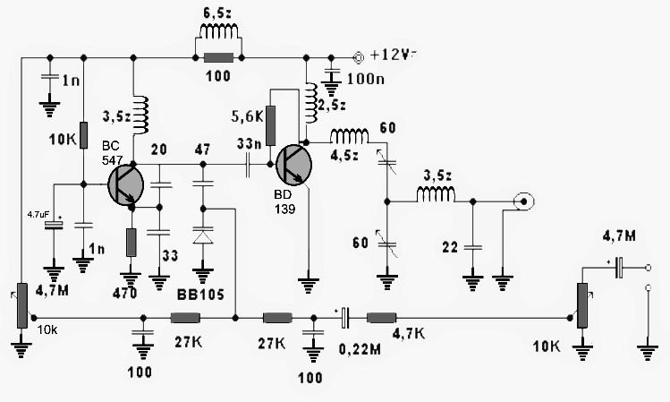
This little transmitter will allow you to communicate, chat, send music transmission on any standard FM Radio tuned within the existing band, across a radial distance of not less than 500 meters or half a kilometers.
Warning: Using this transmitter could be illegal in your country or area, take appropriate permissions before indulging.

How it Works
The circuit of this 1.5 watt transmitter is fundamentally configured for driving a tuned RF amplifier stage by an oscillator stage.
Referring to the diagram we find that the BC547 is rigged in a oscillator mode which resembles a Pierce oscillator circuit.
The base of the BC547 is biased by the 10k resistor, and the crucial RF coil is connected across the collector/positive of the transistor.
As soon as power is switched ON, this coil is resonated by the 20pF capacitor across the transistor collector and emitter.
The 33pF capacitor makes sure that the capacitance does not exceed the maximum specs of the design.
The above capacitor also determines and fixes the working band frequency of the circuit which is within 80 MHz and 110 MHz.
The varicap diode is included in order to convert the fed input voice or music signal into riding electrical pulses over the carrier frequency created by the above discussed oscillator stage.
This modulated signal is fed to the base of the amplifier stage consisting of the BD139 transistor via a bocking 33nF capacitor.
The BD139 picks up the signals and matches it up with the tuned network across its collector terminals formed by the two inductors and a couple of capacitive trimmers.
These trimmers must be adjusted precisely so that the input modulated signal is optimally amplified by this stage and results in a maximum transmission output.
The output is terminated through another inductor which removes unwanted harmonics and feeds a clean amplified RF modulated signal over the connected antenna.
Antenna Specifications
The antenna should be a Yagi antenna as used for old TV sets.
The circuit must be attached very close to the antenna, preferably directly with the connecting points of the antenna.
The power supply can be fed from an external source, or a battery may be used for the same.
All the "earth" symbols must be joined together and terminated over a large copper base positioned right under the PCB...this need be done if a designed PCB is not used.
With a well designed PCB, the "earth" points must be terminated with the inbound large copper tracks which should cover the entire area of the PCB running beside the connecting tracks all across the board.
How to Set the presets
The two 10k pot may be used for optimizing the signal strength or the volume of the fed signal which is to be transmitted.
The BD139 will require a large heatsink attached with its tab.
How to Build the Coils
The term "z" associated with the coils refer to the "turns" or number of turns. For example 3,5z refers to 3.5 turns, 2,5z denotes 2.5 turns and so on.
All the coils for this 1.5 watt transmitter circuit use 0.6 mm super enameled copper wire wound over an air core having a diameter of 5 mm.
