In this post I have explained a 555 based PWM circuit which can be implemented as a 150 nos or more LED light intensity controller circuit. The idea was requested by Mr. Anil
The Circuit Request
I want to run 150 nos LEDs of 5mm with help of IC 555 on Pulse & continuous mode.
I want use 12V/5A DC supply
Thanks & early reply is highly appreciated.
Thanks & regards
Anil Rustagi

The Design
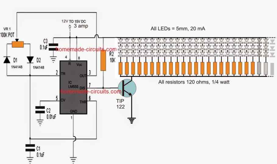
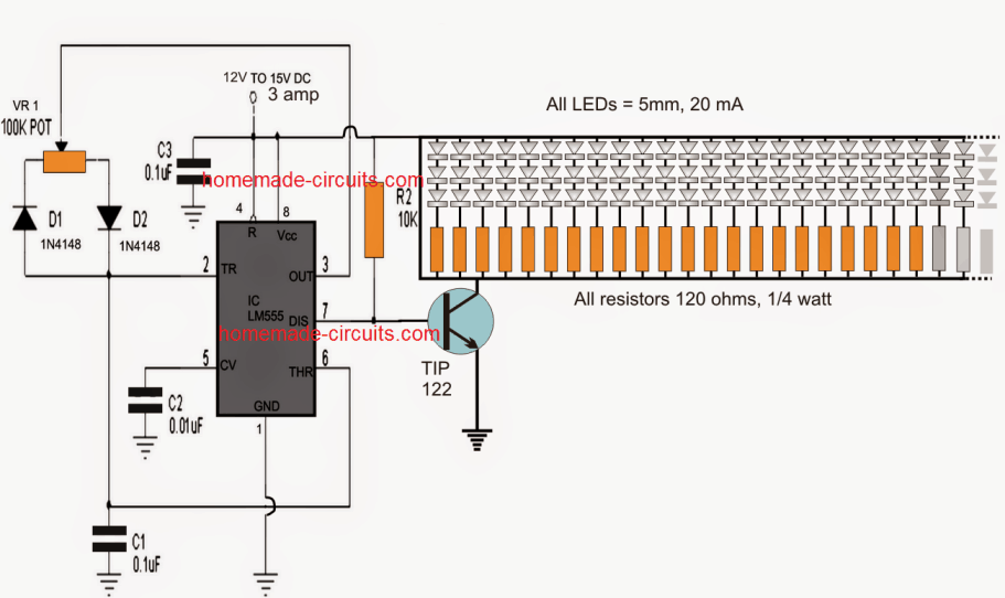
The figure shows a PWM based LED intensity controller circuit using the IC 555.
IC 555 are popularly used in most PWM based circuit applications due to their easy configuration and precise PWM generation ability which is adjustable right from minimum to the maximum.
In the shown design the 555 IC is configured in its standard PWM mode with a slight variation wherein it's discharge pin7 is used as the output instead of its usual pin3 which is rather employed for the discharge function here.
The above configuration makes the functioning a bit more efficient and allows the spaces of the duty cycles to be sharp and more accurate.
Pin7 becomes responsible for creating negative pulses only for the attached transistor, while the positive pulses are derived from the 10 k resistor across the base and positive of the transistor.
VR1 is used as the PWM control pot which almost provides a range from zero to the maximum supply voltage for the LEDs through varying ON/OFF duty cycles as determined by the setting of the 100k pot
TIP122 is rated to hold upto 5 amp with adequate heatsinking meaning more than 150 LEDs rated at 20 mA each can be included with the device as shown in the circuit diagram.
