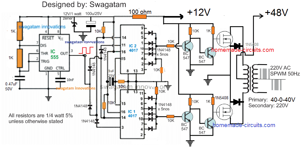
A vey basic yet reasonably efficient 1500W PWM based sinewwave inverter circuit can be studied under this post. The design utilizes very ordinary parts to accomplish a powerful SPWM type inverter circuit.
Main Specifications
Power Output: Adjustable from 500 watts to 1500 watts
Output Voltage: 120V or 220V as per the transformer specs
Output Frequency: 50Hz or 60Hz as per requirement.
Operating Power: 24V to 48V
Current: Depending on the Mosfet and transformer Ratings
Output Waveform: SPWM (can be filtered to achieve a pure sinewave)
The Design
The proposed 1500 watt PWM sinewave inverter is designed using extremely basic concept through a couple of IC 4017 and a s single IC 555.
In this concept the sequencing logic from the output of the IC 4017 are configured by selecting and skipping subsequent pinouts such that the resultant sequencing produces a decent SPWM like switching on the connected mosfets and the transformer.
The complete schematic could be visualized in the following diagram:

The working of the Inverter can be understood from the following explanation:
Circuit Operation
As can be seen, two IC 4017 are cascaded to form an 18 pin sequencing logic circuit, wherein the each negative pulse or frequency from the IC 555 produces a shifting output sequence across each of the indicated outputs of the two 4017 ICs, starting from pin#9 of the upper IC upto pin#2 of the lower IC, when the sequence is reset to initiate the cycle afresh.
We can see that the output of the IC 4017 are intelligently tapped by skipping and combining sets of output pinouts such that the switching to the mosfets achieves the following kind of waveform:

Acording to the waveform, the start and the end sequences can be seen being skipped by eliminating the relevant pinouts of the IC, similarly, the second and the 6th pinouts are also skipped, while the second, 4rth, 5th, 6th pinouts are joined for accomplishing a decent SPWM like pulse form across the outputs of the two 4017 ICs.
Video Proof (100 watt example)
The Objective behind this Logic Configuration
The above shown waveform is selected so that it is able to replicate the actual sinusoidal or sine waveform as closely as may be possible.
Here we can see the initial blocks are eliminated so that the SPWM waveform can match the actual sinewave's initial lowest RMS value, the next two alternate blocks imitate the average rising RMS within a sinewave, while the center 3 blocks tries to replicate the maximum RMS of an exponentially rising sinewave.
When the above PWM format is applied to the gates of the mosfets, the mosfets alternately execute the switching of the transformer primary with the very same switching format in a push pull manner.
This forces the secondary synchronously to follow the induction pattern with an identical waveform which ultimately results in the creation of the required AC 220V, having the above SPWM waveform pattern.
An appropriately dimensioned LC filter across the output winding of the transformer may finally allow the secondary side to achieve a perfectly carved sinusoidal waveform.
Therefore when the resultant output of this SPWM is filtered should hopefully result in the replication of a sinewave output which could be suitable for operating most electrical appliances.
The Oscillator Stage
An ordinary IC 555 astable is implemented here for creating the required clock pulses for feeding the cascaded 4017 ICs and for enabling the sequencing logic across their output pinouts.
The R1, R2,and C1 associated with the IC 555 must be accurately calculated so that pin#3 is able to generate around a 900Hz frequency at around 50% duty cycle.
A 900 Hz output becomes necessary so that the sequencing across the total 18 pinouts of the 4017 ICs causes the BJTs to trigger at a 50 Hz across the two channels, and at around 150 Hz for chopping the individual 50 Hz blocks.
About the Mosfets and the Transformer
The mosfets and the transformer of the above explained 1500 watt SPWM inverter circuit are the two elements which determine the total power output.
For getting a 1500 watt output make sure the battery supply is not less than 48V, at 500 Ah, while the transformer could be anywhere around 40-0-40V/ 40 amps.
The mosfets can be IRFS4620TRLPBF each if 48V battery is used, a pair of these mosfets would be required in parallel on each channel for ensuring proper delivery of the full 1500 watts at the output
If you have any doubts or personalized queries, please feel free to add them in the comments below for getting quick pertinent replies.
