The post presents a simple transformerless 1.5V DC power supply circuit which can be used for powering wall clocks directly from mains, and also keep a stand by back-up cell fully charged for enabling an uninterrupted operation of the clock even during mains failures. The idea was requested by Cheekin
Warning: This circuit is not isolated from mains AC and therefore is extremely dangerous to touch in powered condition, users are advised to apply extreme caution while handling it or testing in an uncovered position.
The Design
The figure shows a simple 1.5V transformerless power supply circuit for wall clocks that would never allow the clock to stop due to a depleted battery as it would keep running from the mains and also be reinforced with a battery power to ensure that the clock does not stop even during a mains failure.
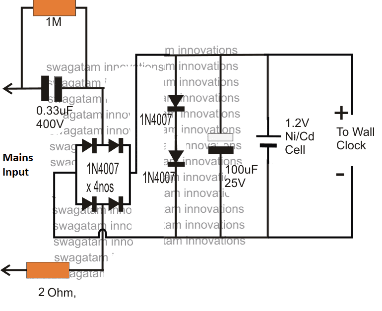
The below shown design is a simple transformerless power supply using a 0.33uF capacitor as the input current limiter component in order to restrict the mains current to a modest 16mA.
Circuit Diagram

Hopefully this current will keep the clock ticking satisfactorily and also keep the attached Ni/Cd cell trickle charged and ready for an emergency back up.
If the 0.33uF does not provide adequate current for the operations, you can increase it to a higher value which just satisfies the application needs.
The indicated 1.5V transformeless power supply for a wall clock is able to develop the required 1.5V DC at the output with the aid of the two forward biased 1N4007 rectifier diodes across the (+), (-) terminals of the supply, which effectively shunts the massive 330V mains (@ 20mA) to a nominal 1.5V DC.
The inclusion of the two shunting diodes also ensures an entirely surge free supply for the clock and the charging cell, and therefore the design is relieved from other conventional forms of surge protection devices.
How it Works
Briefly the 1.5V transformerless supply circuit for clocks can be explained as follows
The mains input current is dropped to a lower 20mA by the 0.33uF/400V capacitor.
The bridge rectifier converts the above low current input to a low current DC variant, which is further acted upon by the two 1N4007 diodes which shunts the DC to a fixed 1.5V approximately.
This 1.5V / 20 mA DC is finally used for operating the desired wall clock, and also for charging a connected 1.2V Ni/Cd cell which reverts its DC each time mains fails, ensuring a failproof uninterrupted supply for the clock so that the unit never stops due to any adverse reasons.
Hello Again Swagatam,
I hope you are doing well.
I just tried the final 1.2v circuit you sent earlier, and it doesn’t work as expected. The LED is lit okay, but the battery doesn’t charge, and the output is pretty high.
AC input is 220v – 230v
The voltage for the battery is 1.3v DC.
The voltage for the output is 2.3v DC.
Which is entirely wrong! It should be 1.5V or 1.6V for the battery and 1.2V for the output load.
Here is the final circuit I just made:
final-circuit-not-working-as-expected
Thank you Waleed,
You are saying the following circuit is wrong:
" rel="ugc">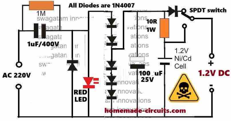
I am sure you have understood the technical aspects of the design, so I am interested to know how the output to the load can be 2.3V?
And how the voltage to the battery can be 1.3V?
Let me explain you how it works, for your understanding.
You can see the bottom 3 diodes in series, together they clamp the output voltage to 0.6 * 3 = 1.8V. The series diode near the switch deducts 0.6V again, making the output voltage to the load 1.8 – 0.6 = 1.2 V.
Since the battery is connected before the above diode, it gets the full 1.8V, which is OK, because the 10 ohm diode limits the current to the battery and restricts it to the required safe limit.
By the way how did you measure the voltages?
You must measure the voltage without the actual load and the battery, in the following manner:
Replace the battery with a 1k resistor and replace the load also with a 1k resistor, and now measure the respective voltages across these 1k resistors.
There may be some differences in the above explained voltage levels… because the 1N4148 may not drop the exact 0.6V across them.
The link you provided is not opening in my computer, please upload it some other image hosting site, I will check it out.
Hi Swagatam,
Thanks for the quick reply.
First, I tested without connecting the SPDT button to check the output voltage.
As you said, I double-checked and tested before connecting the battery without a load connection.
The battery’s voltage is 1.3v, and the load is 2.3v even after connecting the battery, but not the load.
Here are the hosted images:
Final Circuit:
https://drive.google.com/file/d/1eIlkEUWOSQXNEuIo21mf5t8uhH1Y6XFM/view?usp=sharing
With the battery:
https://drive.google.com/file/d/16T3Umn0FN_hwy6FYKnp4xQ36yYKGNJUH/view?usp=sharing
Without the battery:
https://drive.google.com/file/d/1TnkBNK2xR1_4je-6FDbARO2wUjuMuk0P/view?usp=sharing
Please check if I connected something wrong.
I appreciate any help you can provide.
Hi Waleed,
You circuit connections are correct.
Now please replace the battery points with a 1k resistor and check the voltage across this resistor and let me know.
Remember, the output voltage will ultimately depend on the individual diode’s forward voltage drop specifications, which is beyond our control.
I completed the circuit by connecting the 1.2v battery and the DC motor, but the battery was still not charging, and the motor stopped after the battery died. Ok, I’ll connect the 1k resistor and tell you the voltage.
Here is another image of the completed circuit:
https://drive.google.com/file/d/1GU3YsGjSm7ufsTMRqYtDY9eggwhAbWy4/view?usp=sharing
The battery will take 7 to 10 hours to charge and during this time the motor should not be used with the battery.
Hi Swagatam,
I have connected 1k resistor and the voltage between it is only 1v DC but when turn the motor on the voltage drop to 0.9v or less.
I also tried to remove the led and the same output still occur 😔
Thank you Waleed,
As I said earlier, the final voltage will depend on the diode forward drop specifications. 1V instead of 1.2V is OK, because it is just 0.2V less, it is impossible to get exact 1.2V using diodes only.
If your trimmer working without issues then it is fine. The 0.9V drop also looks fine to me.
If the trimmer is not working good, then you can try increasing the input capacitor value to 1.5uF/400V, or add a 474/400V (0.47uF/400V) cap to the existing 1uF/400V.
Hi,
Maybe calculations are a thing, and real-life testing is another thing.
I said the battery’s charging voltage now is 1v or less not for the load, and you said it takes 8 hours to charge!! I know it takes that long, well, but the charging voltage should be at least 1.5v, so now the battery does not trigger the charge action.
Get my point?
I know the charging voltage must be 1.5V, that’s why i have tapped the voltage after series 3 diodes. Each diode drops 0.6 to 0.7V, so adding them gets over 1.5V.
You must first check whether the 3 series diodes are generating the voltage above 1.5V or not.
Did you check by connecting a 1k first?
Yes, I checked before and after connecting the 1k resistor, and it generates from 1v – 700mv – 400mv. Can you please re-check the required components and the connection once again? Is it possible to apply it yourself? I know you don’t have enough time.
I have explained you the function of the diodes, so please check the voltage across the 3 series diodes, and then across each of those 3 diodes. Do this with the 1k connected and without any battery or motor connected.
This will tell you why your circuit is generating 1V only.
By the way the voltage should not fluctuate between 1V, 0.7V. 0.4 V, otherwise it means something’s not right with your components.
The circuit diagram is correct.
Hello,
I think things are easier than using a 7uf cap!!
Most trimmer devices I have (Philips & Braun) run “only” if a battery is installed. If you remove the battery and connect the 220v, the device won’t turn on. This is simply because the battery is the circuit completion part; if it is missing, it means the circuit isn’t complete.
So, I think it’s better to follow what big companies do. They simply say the device works with and without 220v mains on, but the battery is essential.
Why?
In the first criterion (without mains on), the device relies on the battery installed, which gives the motor the required voltage (1.2v or 2.4v) with proper Mah.
In the second criterion (with the mains on), the device relies on a battery charging situation, which gives the battery enough power to run the load. Even if the battery is damaged or weak, there are no issues. The battery works as a connector between 220v mains, only delivering power to the DC motor.
I have a simple 2.4v circuit (only using tiny SMD components instead of a vast capacitor (which will never fit in the device).
The device is using simple SMD components:
M7 diode
T4 diode
Small Conductor
SMD cap
104j cap
SMD resistors
Small Led
1D transistor – By the way, do you know what its equivalent is? Is it MMBTA42 SOT23 A42 SOT?
OK, good. If using 104 capacitor charges the battery optimally then you can use it. Also in that case the AC cannot be used to run the trimmer, rather only through the battery.
Glad it is solved now.
Thank you so much. If you open any trimmer or haircut trimmer, you’ll find only tiny SMD components with 2.2uf 400v caps for the input AC. No one runs the DC motor on 220v AC directly.
So,
For the single battery device, a 1.2V, I’ll use your suggested 1.5V Power Supply Circuit in this post.
For the 2.4V 2-battery device, I’ll use your suggested 2.4V Power Supply Circuit with 5 in-series diodes.
Then, I’ll attach an SPDT or an SMD button to power on the trimmer. If the mains input is connected to the trimmer, it charges and can run in both situations. Right?!
OK, I thought you wanted to run the motor on 220V AC as well, that is why I suggested the universal circuit using capacitor.
Yes, If the mains input is connected to the trimmer, it charges the battery and can run in both situations.
However please note that all these circuits not isolated from mains AC, so are extremely dangerous to touch in open and powered condition…
okay, I noticed the extra diode before the spdt switch. does it keep 1.5v for battery charging and let the output for the motor is 1.2v? right?
That’s right!
Thank you so much, Swagatam. I’ll create and test the circuit you recommended and tell you the results (If I am still alive) 😁
You are welcome Waleed, all the best to you!
Hello sir,
Thanks for the efforts you make.
Can this circuit be used to charge and run the Philips Mustache trimmer?
I have 2 machines. One runs on a single 1.2v Ni-CD battery, and the other uses 2 battery cells, which are 2.4v.
So,
Q1: If I used the 1.2v circuit here on this page, would the motor run smoothly?
Q2: What components or changes are needed to make the same circuit, but with an output of 2.4v for the motor and 2.6v for charging?
Thank you so much.
Thanks Be,
No, the above circuit cannot be used and cannot be modified for operating a Mustache trimmer due to lack of sufficient current.
Instead you can use any standard mobile charger and add a BJT voltage regulator at the output to drop the output to the required 1.2V DC.
But you said in the description:
If the 0.33uF does not provide adequate current for the operations, you can increase it to a higher value which just satisfies the application needs.
So, If I need at least 500mah current what capacitor should I use?
It is possible, but not recommended, especially if the load is inductive.
The capacitor value will depend on the current rating of the trimmer motor.
If you tell me the max current rating of the motor then I can tell you the exact capacitor value.
And instead of the series diode regulator you will have to employ a BJT based current regulator.
Hello,
Sure, here are the current ratings for both machines: the one that runs with only one battery cell and the one with two battery cells.
Voltage:1.2V Speed:7850RPM Current:220mA
Voltage:2.4V Speed:15300RPM Current:350mA
Ok, here’s the circuit for the 2.4V trimmer: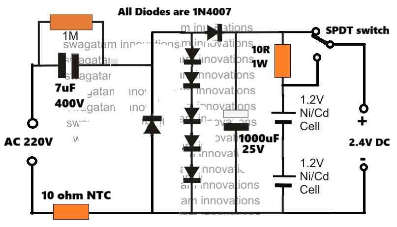
" rel="ugc">
Unfortunately a switch cannot be avoided because the charging current is 70 mA for the battery and the operating current of the trimmer is 350 mA.
For the 1.2V/200mA trimmer, you can use a 5 ohm series resistor for the battery, remove two 3 diodes from the series chain so that only diodes are there in the series chain, and use 4uF/400V for the input capacitor.
Hello sir,
Thank you so much. I appreciate your superb help.
But how do I add that huge 7uf 400v cap into the small trimmer? or do you mean 4.7uf 400v (my old trimmer has 2 caps 2.2uf 385v connected in parallel).
Also, could you send a quick diagram of the 1.2v circuit you mentioned with 5-ohm series resistors? I’m sorry; I’m still a newbie.
Also, there are no 4uf caps in my country.
No problem Be,
The 7uF capacitor is required for generating the 350mA current for the motor, so it cannot be avoided.
The 4uF is for the other trimmer rated at 220mA. For this you can use two 2.2uf in parallel.
The diagram for the 4uF capacitor design (1.2V) is similar to the previous diagram, except the number of diodes connected in series vertically and the input capacitor.
" rel="ugc">
In the above diagram you can see the vertically connected series 5 diodes, here you must remove two diodes and use only 3 diodes.
And replace the 7uF/400V capacitor with 4uF/400V.
That’s all, you only have to do the above modifications, rest everything will be the same.
Hello,
I have re-checked, and I think using this circuit to run the Bread Trimmer is okay. As you said, if the mains current is cut off, the load will run on the battery.
So, I mainly use the machine wirelessly without attaching it to the mains unless it needs to be charged. Right?
Q1: Do you think 20mah is enough to charge a 1.2v ni-cd battery?
Q2: What If I used a 1uf polyester capacitor instead of 0.33uf? Do I need to change anything else in the circuit, like resistors or output capacitors, or can I keep everything as is and only change to a high UF value?
Also, do you have any ideas on how to make the output 2.4v or 2.6v?
Thank you.
Hi, Ok, if you want to use above circuit to charge your battery and also operate the trimmer motor then you may have to include additional current regulation circuitry.
The current from the capacitor should be 10% of the battery mAh.
So please check the mAh rating of your battery, then i can suggest you the correct design for your application.
Although the output voltage is supposed to auto-adjust to the load voltage spec (because of the current regulation), the series diodes can be further adjusted to regulate the output voltage to the nearest appropriate level.
Hello,
Thank you so much for your interest.
The battery’s mAh rating is 700mah (each).
Hi Swagatam,
I am wondering how to add an indicator LED to this circuit. Do I need to attach a 1k resistor to the negative leg of the LED and then connect it to the circuit’s negative line, or what?
Also, what if I want to increase the current slightly? Let’s say 100 MAH! What to change? Only the polyester cap with a higher value of 1uf 400v? or 1.5uf 400v?
Thank you so much.
Hello Waleed,
You can add the LED directly across the output through a series 1k resistor, but it will then drain the battery also. The resistor can be in series with the positive leg or negative leg of the LED.
To increase the current you can just increase the values of the 1uF to a higher value. A 1uF will generally produce around 60 ma current.
Hi Swagatam,
Thanks for the quick reply.
“It will then drain the battery also.” So, is there any trick to prevent the battery from being drained without using the load?
Also, is there a way to prevent battery drain even if the LED is added? Most devices have a small indication LED, right?
Hi Waleed,
Can you please tell me what exactly should the LED indicate in the circuit? I will try to solve it for you…
Hi Swagatam,
Well, I only need to know that the AC 220v main is on, so when the AC is plugged in, the LED turns on, and vice versa.
I know that charging complete and cutoff options are complicated; I only need to know that the AC main is plugged in.
Hi Waleed,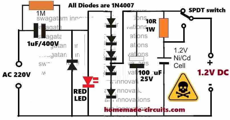
You can try the following circuit: The LED does not require a resistor since the voltage is regulated at 3V for the LED…
" rel="ugc">
Hi Swagatam,
I’m sorry I cannot reply to your last message (I don’t know why).
Anyway, I got the final image of the circuit with the LED indicator.
But I noticed that the output is only 1.2v (it’s great for the motor).
It won’t be enough to charge the battery. It needs at least 1.5v or a bit higher. Right? Or do I understand it wrong?
Yes, you are right, in that case please try the following design.
" rel="ugc">
After 10 replies the comment thread closes automatically, that is why we cannot reply after 10 comment replies are over…
Hi Swagatam,
I’m sorry but the last image you sent is the same as the previous one = the output still 1.2v and no difference 🤔
Hi Waleed, in the new diagram the diode configuration is different. Yes, it allows 1.6V for the battery charging and restricts the output to 1.2V for the motor operation.
Hello again Swagatam,
How are you? I hope everything is okay.
I played a bit with the circuit and finally got it to work as needed.
I removed one diode from the two right after the LED, and the voltage increased from 1.1v to 1.6v as needed. When I connected the battery, the voltage decreased to 1.4v, which is slightly enough to trigger the charging.
What do you think?
Before removing the diode, I removed the LED, and the voltage increased to 2v. When I connected the battery, the voltage decreased to 1.7v, which is great for charging.
But I need the LED. Is there a way to increase the voltage to 2V without removing the LED? Should I remove the second diode?
I removed the one with the red X. Shall I remove the other one from the red circle?
Please check the attached image.
" rel="ugc">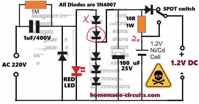
Thank you Waleed, I am good!
Please remember that the voltage for the battery charging must be checked “without a battery connected”. And when the battery is connected, this voltage must drop to the discharged level of the battery.
So if your 1.6V is dropping to 1.4V, that’s correct, and the drop is indicating that the battery is consuming the current and charging.
As the battery charges up, this level will slowly increase across the battery terminals until 1.6V is reached.
1.7V after connecting the battery is NOT great for charging, it is bad, and this might damage your battery slowly.
The initial 1.6V without battery connected is the correct setting, which should be good for the battery.
So you can keep the LED connected.
Okay, I’ll keep the current settings as is and check for other battery cells. Thank you so much.
Sure, no problem, let me know if you have any further issues with the circuit.
Sure, but the charging is very slow!!! Is that okay? And how long does it need to reach 1.4v or more with these settings?
Also, is there a way to replace the 3-pin SPDT button with the 2-pin one?
Ni-Cd cells have similar characteristics like lead acid batteries, and might take minimum 10 to 15 hours to charge fully with a recommended safe charging current that is around 10% of its mAh rating.
If you increase the current, it will charge the cell faster, but it may have its own disadvantages and cause reduced life span of the cell.
With 2 pin switch you an only toggle the power ON/OFF, you cannot select between load through battery power or load through AC mains.
Hello Swagatam,
Okay, there is no problem with the charging time. But I can’t seem to get the second part of your reply?!!!
Currently, I can run the load only on the battery, even if the AC mains is connected.
Please check the attached image to see if I connected it the wrong way!!!
As you can see, I connected:
The yellow line comes from the last diode to the first pin of spdt.
Connected the battery-positive red line to the spdt center pin.
Connected the 3rd spdt pin to motor positive.
Connected the battery negative black line to the motor negative.
I can only run the motor with this connection if the center and 3rd pins are met.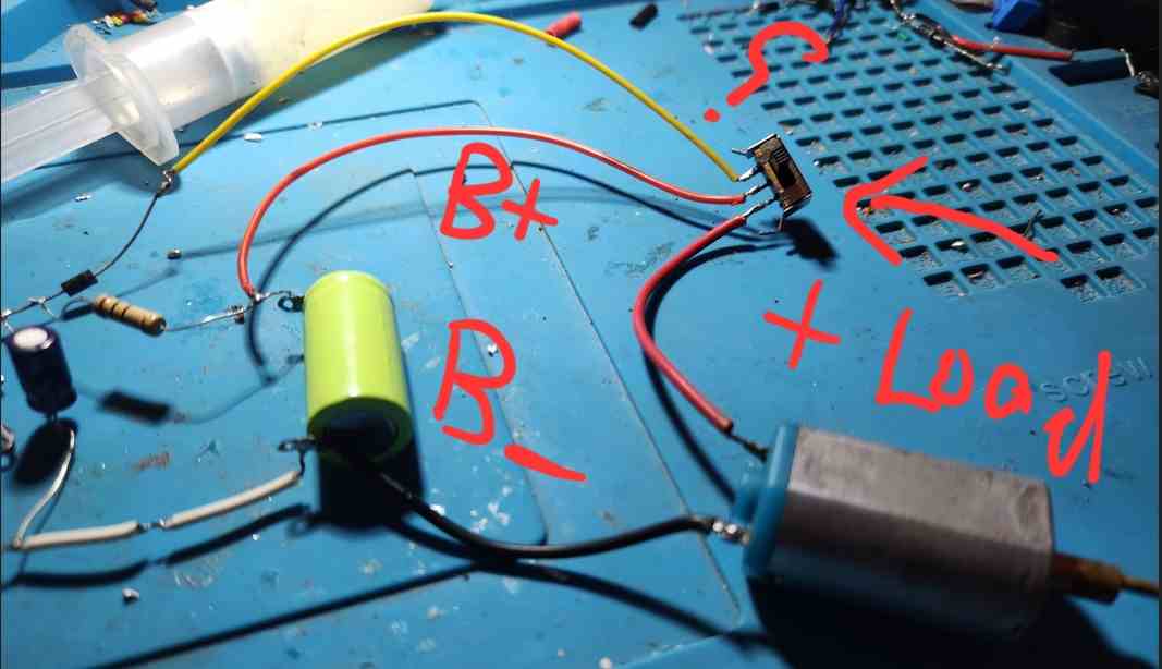
" rel="ugc">
Hello Waleed,
You can see in the previous schematic, the center pin of the switch goes to the load. So please swap the two RED wires and make sure the center pin of the switch connects with the load (motor).
Hello Swagatam,
How are you today? Sorry if it bothers you.
Well, I tried your instructions and swapped the lines. The motor is positive in the center between the battery and mains.
But it still works only on battery 🙁
I measured the voltage when the first line (circuit positive end line with the diode) and the voltage was 1.3v without the motor connected, but when I ran the motor, the voltage disappeared, and the red LED dimmed.
What do you think? Shall I remove the diode, or what?
Also, how would the connections be if I wanted to connect only 2 pins SPDT?
Sorry for asking too many questions.
Thank you Waleed,
Please check your motor current specifications. The 1uF/400V can supply a maximum of 60 mA only, which might not be sufficient for the motor.
You may have to increase the input capacitor value according to the motor’s Amp specifications, and also upgrade the battery series resistor accordingly.
Hello Swagatam,
How are you?
I replaced the 1uf polyester cap with a slightly higher one (1.5uf 400v) with the same settings, but the motor still did not work on the mains.
As I told you before, the motor current is 350 mA.
You recommended that I use a 4uf 400v cap. I searched for it on my staff and could not find it.
Is it okay to use 4.7uf 400v (Electrolytic cap) instead of polyester?
What is the difference?
Also, I have 8.2uf 400v (Electrolytic cap). If I used it, are there any components I could change?
If electrolytic caps do not work, what will the current be if I use 3.3uf 400v polyester (which is available in my area)?
Thank you.
Hello Waleed,
If 1uF generates around 60mA, then you may require around 350/60 = 6uF/400V capacitor for generating 350mA current.
Electrolytic will not work and will burst after sometime.
3.3 * 60 = 200mA, which might be not sufficient for your load.
Make sure the series resistor with the battery is appropriately calculated using Ohms law
R = V/I = 1.2V/0.07mA
Hello Swagatam,
How are you?
It seems I need a capacitor as large as an apple 🙂
Well, I tried adding a 3.3uf cap to run the motor on AC 220v, but it’s not running. I’ve tried increasing it by connecting 2 caps together to get 6.6uf, and it’s barely running.
Finally, I tried to add 2 caps, 4.7uf / each, which gave me 9.4uf, but the motor ran very slowly.
So, I think it’s better to stick only with the battery as the main source of power.
Finally, is there a way to run the motor with a push button instead of the SPDT one?
Thank you Waleed,
It seems your motor requires more than 500 mA for operating optimally.
You can confirm the actual rating of the load by adding an ammeter in series with the battery supply and the load.
For using a push button, remove the SPDT switch and the extra single diode at the output.
After this just wire the push button terminals in series with the positive of the battery and the load positive.
The other wire of the load will connect with the negative of the battery.
Hello Swagatam,
Okay, but I think there are many ways to increase the ampere instead of just increasing the capacitor value, such as adding an amplifier transistor.
Regarding the push button, I already replaced it and connected the two wires with the positive and negative of the output, but it only runs when I keep pushing it; if I release my hand, the motor stops.
I need a single click to run and another to stop it. Is that possible, and if not, why?
Sorry for those annoying questions 🙂
Hello Waleed,
The capacitor controls the input current, so a transistor can do nothing. The transistor will supply only what the capacitor provides.
Push to ON and OFF function can be implemented with an extra complex circuit, which is not recommended according to me.
Okay, according to you, I’ll stick with your previous instructions.
But can you please show me how to connect the push button to the current circuit in a simple diagram or handwritten image?
I already connected one but canceled the final output diode, so I got the positive line right after the 10R resistor and the negative from the battery. Is that okay?
One terminal of the push button will connect with the battery positive.
The other terminal of the push button will connect with the motor positive.
The negative of the motor will connect with the battery negative.
That’s all.
You don’t need the output side single diode and the the SPDT switch connections, so you can remove them all.
Let me know if you understood the connections or not.
Waleed, I just forgot to tell you that the current to the load can be doubled simply by using a bridge rectified instead of a single diode at the input. here’s the full diagram with the push button attached: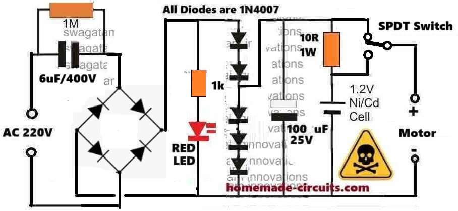
" rel="ugc">
Try this and check if the motor operates correctly or not.
Hello Swagatam,
Thanks for your interest.
I told you there should be some way to increase the current instead of expanding the capacitor.
Anyway, I’ll try the recent circuit and tell you the results.
I am using a 1.5uf cap, so if the current doubles, will that affect the LED?
I tried increasing the current as you described before, but the high current burned 3 LEDs.
Shall I add a 1k resistor to the LED to protect it from high current?
Hello Waleed,
The capacitor is the one and the only way to increase the current, there’s no other way to increase the current.
The bridge rectifier is merely allowing the both the phases to reach the load, which was being inhibited by using a single diode.
The LED is always safe due to the presence of the 5 series clamping diodes. 5 * 0.6 = 3V fixed across the LED. The LED will burn if the diodes happen to have a forward drop of 0.7V or higher, in that case 0,7 * 5 = 3.5V which also looks ok, although risky.
You can add 1k for extra safety to the LED.
Also, if I doubled the current, it’s better to use the SPDT button to run the motor on both the battery and direct AC. Right?
If you use a push button rated at around 1 amp or higher, then the push button will be also safe.
Hi again,
regarding the final circuit you sent. I noticed that there is a 10R 1w resistor. I only have it on 1/4w. is it okay or should it have to be 1w.
also for the spdt button, I want to replace it with push button 4 legs is it okay?
Hi Waleed,
1/4 watt resistor should also work. Check if it is heating up or not (after switching off power), if not then it is fine.
If the push button is momentary type, then it will not work, it should be a 2-way toggle switch.
Dear Sir Swagatam
I hope this letter finds you well. I am writing to ask for your assistance with a question that I think is somehow related to this article.
I have recently purchased a corded Panasonic telephone set that requires three 1.5V alkaline batteries to save the settings I have programmed into it (Ni-Cd batteries are not allowed). The issue is that these batteries are somewhat expensive and I need to replace them every six months as per the instruction booklet.
My plan is to install a socket in the unit and connect the the secondary 4.5V output of a 220/4.5V adapter using a 1N4007 diode.
I am hoping that the unit will run continuously on the adapter power, switching to battery power only when the city electricity is disconnected.
Waiting for your kind assistance, I remain.
Best wishes
Max
Hi Max,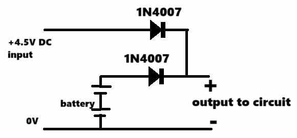
What you want to accomplish may be possible, however you may have to open the unit and wire a couple of diodes, as shown in the following diagram, in order to achieve seamless power transfer during power failures.
" rel="ugc">
However the 1N4007 might drop 0.6V so you might consider using schottky diodes.
Dear Sir Swagatam
Thank you so very much for your kind response and the circuit diagram that you drew for me .
I am writing to inform you that another method came to mind, which is to use a relay instead of diodes. I have already sent a picture of the circuit to your Email address. As you can see, when the plug of the 220/4.5 V adapter is connected to the city power, the relay is activated and the “NC” pin of the relay is separated from the “C” pin; this removes the battery from the circuit, allowing the phone to be powered by the adapter. As soon as the city power is cut, the “NC” pin is connected to the “C” pin again, and the 4,5 V battery powers the phone.
I would appreciate your instructions on this matter, dear Swagatam.
Best wishes
Max
Thank you Max,
I saw the diagram you sent to my email. Yes, using a relay is possible, but the slight delay across the relay contact operation can cause the phone data to get erased, that’s why I suggested the diode method, which allows seamless transfer of power ensuring the phone data does not get impacted.
Dear Sir Swagatam
Thank you very much for mentioning the vital tip. I will do the diode method as per your instruction with schottky diodes and will never forget your kindness. God bless you Sir.
Best wishes
Max
You are most welcome Dear Max, all the best to you.
Let me know if you face any issues with the circuit….
Dear Sir Swagatam
I hope you are doing well. Once again, I need your help, sir. Would you please instruct me if it is a good idea and safe, of course to reduce the 5V output voltage of a Nokia 350mA cellphone charger (when measuring it, multimeter reads 8 volts) to 5 volts using a 7805 regulator, then reduce it to 4.5 volts using a 1N4007, and afterward connect this 4.5 volts output to your proposed circuit diagram?
" rel="ugc">
Thank you in advance for your assistance
Best regards
Max
Thank you Max,
I think feeding a 5V DC input to a 7805V output will produce an output that may be lower than 5V, it may be around 2V lower, meaning the output could be around 3V.
So, please confirm this practically, how much voltage you get at the output of a 7805 IC in response to a 5V DC input.
Please let us know about it.
Dear Sir Swagatam
I am writing to provide an update on the results regarding the Nokia charger with an 8-volt output without a load. When connected to city electricity at 200 volts, the output voltage after connecting it to the 7805 IC was 5 volts. However, after adding the 1N4007 and 1N5819 diodes, the voltage dropped to 4.5 volts; a desirable voltage. I then connected a lamp to the output, drawing 50mA of current and observed that the voltage decreased further to 3.8 volts.
Regarding the other charger that I had previously sent a picture of to your email address, it was found to be faulty and I set it aside.
I eagerly await your new instructions, dear Swagatam
Here, I want to express how grateful I am to have you in my life, and your kindness will forever hold a special place in my heart. Your guidance and support mean the world to me, and I am truly thankful for everything you do. Without you, I had no one to answer my questions.
Warm regards
Max
Thank you Max, for updating the results,
So, 3.8 V is the real voltage available, but it is less than the required 4.5V.
So, I think, instead of 7805, it is better to employ the following simple transistorized voltage regulator, which will directly provide you with the required 4.5V accurately:
" rel="ugc">
You can use a 5.1V zener diode, and 8050 transistor.
BD139, SL100, 2N2222 can be also used for the transistor.
Let me know how it goes.
Thank you so much for your response and the substitution circuit diagram, dear Swagatm. I Just wanted you to make you aware that I received your response dated August 18th just now (8/21/2024 5 PM). I will definitely let you know the result.
Warm regards
Max
Thank you Max, That is strange, the reply emails normally reach within a few minutes!
But no problem, you can certainly try the suggested circuit design and let me know how it works for you!
Sir engineer Swagatam
Hello dear,
I am writing to update you on the new tests that I have conducted. Here are the results:
1. I connected a 1000uF capacitor to the output of my 5-volt, 700mA mobile charger that I am using it for my cellphone and is in a health condition. I observed that without a diode connected to the output, the output voltage remained constant with a current of 10mA and decreased to 4.9 volts with a current of 350mA;there was no voltage drop approximately.
2. Next, I connected two 1N4007 diodes and one 1N5819 diode in series with the positive line of the charger. I found that the voltage decreased from 4.7 volts to 4.1 volts with a current of 10mA, and to 3.5 volts with a current of 350mA. This result was unexpected to me.
3. Following that, I tested your proposed transistorized circuit with a 1N2222 transistor. I observed that the voltage decreased from 4.7 to 3 volts with a current of 350mA, and to 3.5 volts with a 10mA load. Given that the collector current of the transistor is 800mA, and the charger delivers more than 350mA, I am puzzled by the values of 1.7 (4.7 to 3) and 1.2 volts (4.7 to 3.5) voltage drops with a load of 350mA. I would appreciate your guidance in this issue. Thank you for your help. I look forward to your instructions.
Sincerely
Max
Thank you Max, for your detailed analysis regarding the previous linked circuit.
It seems your charger is not delivering the 700 ma current, that is why the voltage is dropping with a load of 350 mA.
According to me that can be the only reason behind the drop in voltage.
Because, if the current does not exceed beyond the supply capacity, the voltage will never drop.
You can try reducing the resistor value for our previous regulator circuit from 4.7k to 470 ohms or 100 ohms and check the results. You can also try using a BD139 or TIP31 BJT for 350 ma output:
" rel="ugc">
Let me know how it goes..
Dear Sir Swagatam
I forgot to inform you that; I have another charger labeled 5V, 2000mA (1000mA actual). When tested with a multimeter, it reads 5.5V. I have uploaded a picture of it to your email address. Thank you so much for all of your kindness.
Best regards
Max
Thank you Max, I saw the image of the 5V mobile charger that you sent to my email ID, it looks OK to me, you can use it to feed a 7805 IC for the required application.
Please let us know it goes…
Sir engineer Swagatam
Hello would you please tell me what is the role of the 1M resistor paralleled with 0.33 MF capacitor?
Thank you very much Sir
Truly
Max
Max,
the 1M is connected to ensure that the high voltage capacitor is able to discharge through it quickly when the circuit is unplugged from mains voltage.
Sir engineer Swagatam
Thank you so very much for your response.
you and your site are more than a university.congratulations.
God bless you. Wish you all good things
Max
It’s my pleasure, Max! All the best to you!
hi, read your article with interest. however i m trying make a hack to power a 1.5V battery wall clock (12″ diameter quartz), using a cellphone adapter with a 3.75 v output. (avoid replacing a dead battery, every period)
I figured, with voltage divider, i need to find a resistor to take the 2.25 v. so if i assumed the clock used 2 mA, then R=2.25/.002 ~=1120 ohms; if 20 mA, the R=112 ohms.
I have no ideas the amp used by clock..
pls suggest a reasonable approach. How does one measure the amp the clock will used?
Hi, to measure the current, you can connect a digital multimeter between the positive terminal of the battery and the positive of the wall clock circuit. Meaning, the current from the battery positive must pass through the meter before reaching the clock circuit. The meter must be set to read 1 amp DC or any other suitable nearby range.
Hi sir,
Its sounds great to sharpen our knowledge with you.
Since a 1uF cap provides ~70mA, by assuming I need ~150mA, can I use 2 1uF/400V cap in parallel instead of a 2uF/400V cap?
Thanks in advance ????
Thank you Badarinarayana,
yes you can use 2nos 1uF/400V to get 150mA, although in practically the current will not be 150mA rather only 100 or 120mA.
I am trying to work out the mathematics and understand how to determine the current flowing in the circuit. Since I can’t upload any pictures/sketches, I will try to explain, so please bear with me.
I see that the rectifier and other diodes create around 2.4v drop. The remaining components in the series are the RC pair (1Mohm in parallel to 0.33uF) and the 2ohm in the end.
Now applying KVL:
330 – 2.4 – i*(Z – 2) = 0
where :
i is the current flowing
Z is the net impedance of the RC calculated as Z = 1/(1/X + 1/10^6)
X being reactance, X = 1/(2*pi*f*0.33*10^-6)
Assuming f = 50 Hz, X = 9645.8 and Z = 9553.6
Hence,
i = (330-2.4)/(9553.6-2) = 0.0343 Amp or 34.3 mA
Obviously, the above formulation is valid for the no-load conditions. I don’t know the typical impedance of a wall clock. But surely, the current flowing through mains would increase (>34mA) when load is connected.
Now, how much current flows through the load?
Would it be around 20mA as mentioned in the article above?
How to calculate it?
Theoretically you may get 34 mA, but if you check the current practically you will find it to be less than 25 mA. Assuming the current requirement of the wall clock is 20 mA, then only 20 mA will flow through the wall clock circuit….so it solely depends on the wall clock circuit how much current it requires from the power supply.
If the clock’s current consumption is much higher than 20 mA then it will cause the 1.5 V to drop to lower levels, which would result in malfunctioning of the clock.
Instead of a battery, would it be possible to use a capacitor? I would like to use this power supply for a quartz wall clock (Ajanta is one brand) and since power failures can last for a few hours, designing with a backup time of 24 hours will work nicely for nearly all cases. Thank you in advance.
A capacitor may not last for many hours, therefore a Ni-Cd battery looks the best option
Dear Mr Swagatam… came across your circuit diagram for a wall clock. My son has shown interest and wishes to make one for his school (Grade 9).
Can you simplify it for a 14 year old student who does not know the electronics. Maybe in a video form? Thanks & regards,
Dear Aarjang, I have uploaded the image in pictorial format so that it becomes easy to assemble:
What happened to the 2 ohm resistor? Also, is it a 100uf 25v capacitor or a 10uf 25v capacitor?
no resistor is required here. 100uF can be also used
Wow, quick reply. You are the man, sir. Thank you very much.
No problem, I am always glad to help!
rechargeable battery case just parallel with wall clock + & -, right?
it is the best way for a weak Current, it was nice, thank you
Thanks. I like the idea very much. Circuit will be compact and cheap.
However I think if we replace bridge rectifier with a single diode (half wave rectifier) it can reduce component count, it will be cheaper, and should not affect the wall clock application.
No problem, but with a single diode you will have a connect another diode parallel to the capacitor, with cathode connected with the positive line and anode to negative, to enable discharging of the input high voltage capacitor for the negative cycles.
This circuit is a great simple solution for the clock application, thanks! One question: Would this circuit work as shown for 120VAC mains input (for North American application), with the same 1.5VDC output? Or how would you modify it for that application? Thanks!
Thanks, glad you liked it! Yes definitely, the circuit will continue to produce a constant 1.5 V even with voltages as low as 12 AC. No modifications iare required fr a 120 V AC input
Can I replace the 1.5V cell with a 3.7V lithium battery and use it to power 15leds in parallel ? I I I want the circuit to trickle charge the 3.7V battery when AC mains is available at the same time output to the LEDs.
Yes you can do that, by adjusting the number of 1N4007 diodes accordingly. For 15 LEDs in parallel you will need 6uF/400V capacitor at the input side.
Thank you sir. But in place of diodes, can I just use a 4.1v zener?
If you want to use 4.1 V zener then make sure it is at least 5 watt rated.
Hi,I want to use this circuit to power a 4 tube battery radio with a filament supply requirement of 1.5vdc@ 50ma.The input is 240vac.
Hi, you can use it for the mentioned application.
I came across 3v adapter with just 2 resistor 2 ceramic capacitors one diode one transistor one very small transformer. Now it is not working. What is the circuit and what could be the fault?
If you have checked with a voltmeter, and not seeing any voltage at the output, then the possible cause may be a burnt transistor.
Is there any possibility of over charging of Ni/Cd cell of 1.2 volt 700 mAh, rating AA.
Check the output voltage, it should be less than 1.5V then no chance of any overcharging.
Thanks for the prompt reply. I will do that to increase the load. By the way can you please tell me which component when change will increase or decrease the current.
you are welcome, the input 400V capacitor determines the max current limit for the circuit, the transistor collector/base resistor also determines the amount current which can pass through the transistor to the load…increasing this resistor value will decrease current and vice versa.
Hello Swagatam…
in the above circuit, how to get 200mAh DC output instead of 20mAh?..Thanks
Hi JD, for getting 200 mA use a 4uF/400V as the input capacitor instead of the shown 0.33uF
Thanks…
I always pay attention to this topic and watch anyone will come up any idea to this circuit as mentioned. I will appreciate if you can let me know what will be the voltage without load connected with the modified 3 volt circuit. The second project I made (Ref:January 26, 2017 at 1:57 PM) here I got 1.46V. is it normal this time I fixed with a 2 ohms 5W resistor.Please help. Thanks.
as previously mentioned the output will be almost equal to the zener or the diode value.
to precisely correct this you can replace the zener diode with a 10K pot, and adjust the pot until you get the required 3V or whatever output may be suitable for your load.
always keep a 1K resistor connected across the output terminal to ensure correct reading across these terminals.
Thanks for your quick reply. Do you mean remove the 4 diodes and replace it with the 10K pot and 'always keep a 1K resistor connected across the output terminal' I am not sure what it meant,is it by connecting from the + and – rail before the 100uF capacitor,can you explain with the circuit given. Thanks.
I was referring to the transistorized circuit, in that circuit you can replace the base diodes with a pot for controlling the output, and put a 1K across its emitter and ground line.
if you want to use the circuit which is shown in the above article, then the 1K won't eb required…and the pot cannot be used, it will need to be exactly as given in the diagram.
if the output drops with load, in that case you can try higher values for the 0.33uF/400V capacitor, until the output is able to sustain the load without dropping.
This should definitely have a fuse in series with the incoming mains voltage if diodes where to fail they will explode violently and send over 100vdc to your clock burning it up very rapidly.
It's highly unlikely for the input capacitor to get shorted under any circumstances…even if it does, the 2 ohm would instantly burn and safeguard the cock from getting damaged….
sorry for the typo…I meant to say "clock"
Thanks for you speedy reply. I will tried it out as soon as I am home. One last thing I hope you can help me so I could test and see which will be best for me. The original circuit of the transformerless 1.5V Power supply which you have given is OK for the 1 battery used. Can you tell me the components need to change for a 3V battery (2pcs. 1.5V battery.
thanks, for getting 3V you just have to use 4 diodes instead of the shown two diodes in the diagram, just add two more 1n4007 in series with the existing 2 diodes.
Thanks hardly have to wait will start when I am home. Will let you know the result.
I tried and got this result using the same components (except the zener diode is 3V) in the circuit of 'simplest-dc-cell-phone-charger-circuit'. The voltage in the output is 2V. without load 11V, and with the 10K resistor and the 3V Zener diode in series with 1N14007 I got 1V reading (zener 3V cathode black ring to the base of transistor the other end to 1N14007 anode the cathode white ring to the minus rail. Is there something wrong with component connection or it is normal to get this result. Thanks.
with 3V zener diode the output will be around 2V, that's OK connect a 10K resistor across emitter and ground, this will keep the 2V constant…with 3V+1N4007 the voltage should increase to around 2.7V…verify the base voltage, it will be always around 0.6V more than the voltage at the emitter of the transistor.
Thanks for your reply. Do you mean using the 3V Zener plus adding 1 1N14007 diode in series with the zener diode.
yes 3V zener plus 1N4007 in series, as shown below
base—–I<—–>|——-GND
Thanks for your prompt reply. May I ask is the earlier modification as you mentioned using 3 diodes in series, is it for dropping the voltage to 1.5V. My adapter maximum current is 500ma. as stated in the label how much current is it charging the 2 battery using the 3.6V zener diode. I do have 3V zener diode can it be used for it.
yes they are for setting up a 1.5V at the transistor emitter.
the current will be 500mA at the emitter side.
3V zener will not do, but you can add a 1N4007 in series to make a 3.6V equivalent making sure that the polities for the two diodes are opposite with 1N4007 having its cathode towards ground
One more question for you to solve for me. The circuit which you provided in 'simplest-dc-cell-phone-charger-circuit' is for 1.5V. Can you give me the circuit for 3V. My adapter output is 1 to 12V with 500ma. Thanks.
you can get it simply by changing the shown zener diode with a 3.6V zener diode
Can you please design a simple touch on/off circuit? Function will be one touched power on and then touched again power off the device.Power supply will be 3 to 9v.Thanks Abu Saeed.
you can try the following circuit
https://www.homemade-circuits.com/2016/07/simple-touch-sensor-switch-circuit.html
It is not 3 to 9v operated circuit also can u please make it more simple?
it cannot be simpler than this.
How to modify such that instead of ac 12v-24v dc power supply is given?
if you want to use an adapter, you may try it by attaching the following circuit in between the adapter output and the clock
https://www.homemade-circuits.com/2012/08/simplest-dc-cell-phone-charger-circuit.html
replace 220 ohm with 10K, and 9V zener with two 1N4007 in series having cathode towards the ground
Thanks again for the information.
Thanks for the reply. What I mean is that 'the transistor regulator circuit' if I switch the voltage range from the adapter i.e. say I switch to the range of 3V or any voltage range from the AC to DC adapter it can be used with that circuit.
yes, regardless of the input fluctuations, the output will be regulated to a constant 1.5V using the above linked transistor emitter follower design
Thanks again for the prompt reply. I just wish to ask at the 12V range setting in the adapter is it I can used it for the 3V used even without any further modification.
sorry I am unable to understand your question correctly…a 12V supply cannot be used for a 3V load in anyway
Thanks Swagatam Majumdar may I ask that charger circuit is having 12 volt input, if I used the 12 volt output from my adapter will it be OK for the clock of the 1.5v and 3v.Will be much appreciate if you can let me know what setup for 1.5v and 3v will be to use from the charger circuit.
thanks cheekin, the transistor regulator circuit which I refereed in the link will drop your adapter's 12V to 1.5V after the suggested modifications are done, so it will be fine.
Thanks Swagatam Majumdar for the prompt reply. Can I used 470F 310VAC. capacitor instead of 400VAC. I was wondering in some country sourcing for components is a problem. If we used a AC to DC power adapter with a range of 1.5V to 12V.type what way could we modify it to work properly as without modifying I have a problem the clock does not function properly.
470nF/310V will also do.
if you want to use an adapter, you may try it by attaching the following circuit in between the output and the clock
https://www.homemade-circuits.com/2012/08/simplest-dc-cell-phone-charger-circuit.html
replace 220 ohm with 10K, and 9V zener with two 1N4007 in series having cathode towards the ground
the TIP 122 could be replaced with a BC547
correction: the 9V zener must be replaced with three 1N4007 series diodes.
After much finding everywhere the nearest capacitor according to them is Cap 470nF 10% 310VAC. which they say is same as 470uF 400VAC but with 310vac. Can this type of capacitor suitable for use in this project. Thanks
470nF = 0.47uF
you can use two of them series to make 0.22uF
or use two 0.1uF/400V in parallel.
What's the purpose of the 2 Ohm resistor?
to limit or restrict switch ON power surge current…
Thanks.
Sir can you please let me know why the circuit as mentioned gave me some problem. After a few days in used the time seem to run faster a few seconds. Thanks.
cheekin, did you confirm the voltage of the supply with a DMM? make sure it is not above 1.5V…
you can also try reducing the 0.33uF to 0.22uF/400V and see if that helps to improve the results.
Thanks for the reply. I will try and get the 0.22uF/400VAC capacitor, my place also hard to find capacitor with this type of voltage. The battery appear warm. By the way do you know any electronics components seller which can deliver Malaysia.
you can try contacting any reputed online spare part store for getting the part sent at your destination….
May I know the wattage rating of the two resistors (1M and 2 ohm) which are connected to AC main?
both are 1/4 watt rated
Hi, I don't have 0.33uf/400v cap. Instead I have a stock of 0.47uf/400v. so can I use 0.47uf/400v instead of 0.33uf/400v? Will it make any difference in the output?
Hi, you can use 0.47uF instead of 0.33uF according to me, that won't cause any harm since NiCd cells are rated to handle much more current than 20mA for charging….
Hi I wish to confirm what you mean by 'yes that's possible by adding two more diodes in series with the existing 2 diodes…..or simply replace them with a single 3V 1 watt zener diode.' is it completely removed the 2 1N4007 doides as shown in the diagram and replace it with the zener diode only. Thanks.
yes if 3V zener is used then no diodes will be required at the indicated position….but make sure that the zener polarity is opposite to the 1N4007 polarity
'but make sure that the zener polarity is opposite to the 1N4007 polarity' do you mean the diode connection in the original circuit, I have to reverse the zener diode opposite i.e the + terminal of the zener diode to the + voltage line. Thanks.
the lead of the zener which has a black band will go to the positive rail and the lead which has no band will go to the negative line.
Thank you very much for the prompt reply.
What happens if I took out ni/cd cell. Actually I need clock which run on ac supply and stop when ac mains fail so that I can find out for how much time supply was inturpted.
you can do it if the backup facility is not required.
Thank you for the reply
Thank you for the circuit given. May I ask can the same circuit be used in a 3 volts wall clock (2pcs. of 1.5v battery).
yes that's possible by adding two more diodes in series with the existing 2 diodes…..or simply replace them with a single 3V 1 watt zener diode.