In this post I have explained through two examples how to build a simple110 V or 220 V AC light dimmer circuit for controlling light intensity with pot, using the principle of triac phase chopping.
A 220V dimmer switch circuit is basically a triac/diac based AC mains voltage regulator circuit which can be used for controlling the intensity of an incandescent bulb.

What are Triac Dimmers
We have already seen in many of my earlier articles how triacs are used in electronic circuits for switching AC loads.
Triacs are basically devices which are able to switch ON a particular connected load in response to an external DC trigger.
Though these may be incorporated for complete switch ON and complete switch OFF procedures of a load, the device is also popularly applied for regulating an AC, such that the output to the load may be reduced to any desired value.
For example triacs are very commonly used dimmer switch applications where the circuit is designed to make the device switch in such a manner that it conducts only for a particular section of the AC sine wave and remains cut OFF during the remaining parts of the sine wave.
This result is an corresponding output AC which has an average RMS value much lower than the actual input AC.
The connected load also responds to this lower value AC and is thus controlled to that particular consumption or resultant output.
This is what exactly happens inside electrical dimmer switches which are normally used for controlling
incandescent lights.
Warning: All the circuits I have explained below are connected directly with the mains AC, therefore is extremely dangerous to touch while powered ON and in uncovered condition.
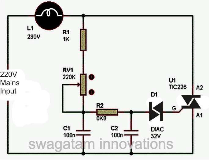
Circuit Diagram of a Simple AC Light Dimmer
Working Video Clip:
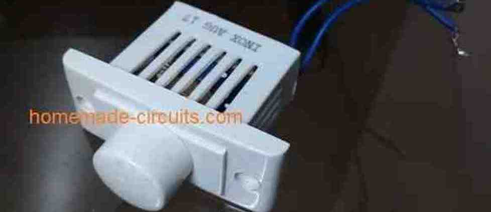
Simple 220V, 120V AC Light Dimmer Switch Circuit
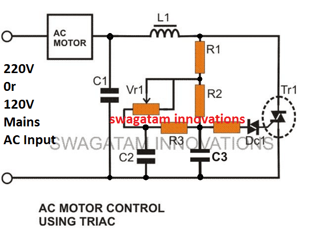
The circuit diagram shown above is an classic example of a AC light dimmer, where a triac has been utilized for controlling the intensity of light.
When AC mains is fed to the above circuit, as per the setting of the pot, C2 charges fully after a particular delay providing the necessary firing voltage to the diac.
The diac conducts and triggers the triac into conduction, however this also discharges the capacitor whose charge reduces below the diacs firing voltage.
Due to this the diac stops conducting and so does the triac.
This happens for each cycle of the mains AC sine wave signal, which cuts it into discrete sections, resulting in well tailored lower voltage output.
The setting of the pot sets the charge and the discharge timing of C2 which in turn decides for how long the triac remains in a conducting mode for the AC sine signals.
You might be interested to know why C1 is placed in the circuit, because the circuit would work even without it.
It's true, C1 is actually not required if the connected load is a resistive load like an incandescent lamp etc.
However if the load is an inductive type, the inclusion of C1 becomes very crucial.
Inductive loads have a bad habit of returning a part of the stored energy in the winding, back into the supply rails.
This situation can choke up C2 which then becomes unable to charge properly for initiating the next subsequent triggering.
C1 in this situation helps C2 to maintain is cycle by providing bursts of small voltages even after C2 has completely discharged, and thus maintains the correct switching rate of the triac.
Triac dimmer circuits have the property of generating a lot of RF disturbances in the air while operating and therefore an RC network becomes imperative with these dimmer switches for reducing the RF generations.
The above circuit is shown without the feature and therefore will generate a lot of RF which might disturb sophisticated electronic audio systems.
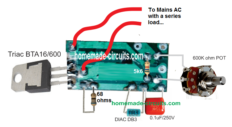
PCB Layout and Connection
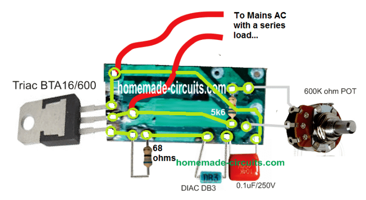
Track Layout Details
Improved Design
The AC light dimmer circuit illustrated below incorporate the necessary precautions for subsiding the above issue.
This enhanced design also makes it more favorable with high inductive loads such as motors, grinders etc.
This becomes possible due to the inclusion of C2, C3, R3 which allows the diac to be fired with consistent short burst of voltage instead of a abruptly switching pulses, which in turn allows the triac to be fired with smoother transitions, causing minimum transients and spikes.
Circuit Diagram of an Improved AC 220V Light Dimmer
Strip Board Connection Diagram

Parts List
- C1 = 0.1u/400V (optional)
- C2, C3 = 0.022/250V,
- R1 = 15K,
- R2 = 330K,
- R3 = 33K,
- R4 = 100 Ohms,
- VR1 = 220K, or 470K linear
- Diac = DB3,
- Triac = BT136
- L1 = 40uH (optional)
SCR AC Light Dimmer
An adjustable RC-type phase-delay AC light dimmer circuit is shown below which consists of R2. R3, and C1.
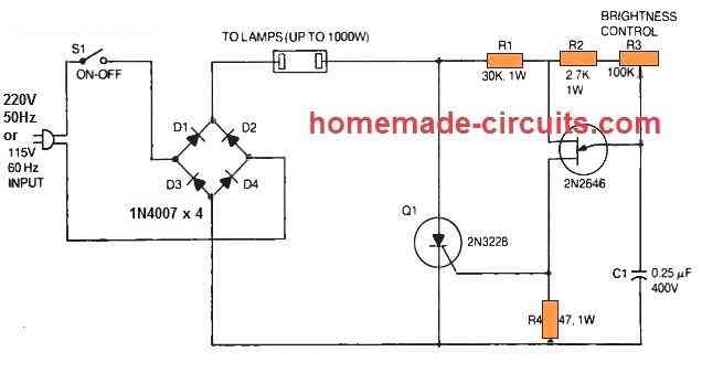
The capacitor C1 fixes the time period where a 2N2646 unijunction transistor (Q2) produces a triggering gate trigger pulse to turn on the 2N3228 SCR (Q1).
By some manipulation of the light-duty control, R3 pot the user is able to change the SCR output across a large range.
In the phase-control circuit, resistor R2 works like a security unit that inhibits rheostat R1 from getting fixed at 100 % anode voltage of the UJT.
This specific rule is applied here to regulate the illumination level of the incandescent lamps, whether as a single lamp or many in parallel as high as to 1000 watts.
In this design, a full-wave bridge rectifier is built using 4nos of 1N4007 silicon power diodes (D1 to D4) that supply rectified power-line voltage for the SCR and the lamp.
Due to the full-wave output from the bridge, it becomes possible for the SCR to take care of both half-cycles of the AC line voltage.
The phase-shift system is sensitive to frequency and has been designed for 60 Hz mains input only.
Therefore the circuit is not going to work with fluorescent lamps and should not be plugged into these.
The 2N3228 SCR 5-amps. 200-volts. but higher-powered SCRs could be replaced for high current applications, and the UJT 2N2646 section of the schematic could be kept unchanged.
Besides SCR circuit is supposed to be used like an AC light dimmer, this circuit can be employed likewise as a heater or oven controller.
I have a device with a 6VAC bulb. I have a power supply of 6VAC, 1.67 Amps. I need a dimmer to go inline to adjust the brightness of the bulb. Is there any available that you know of or do I need to contruct my own and if so do you have any info on the schematic to build one?
Please try the following circuit design, I think it should work: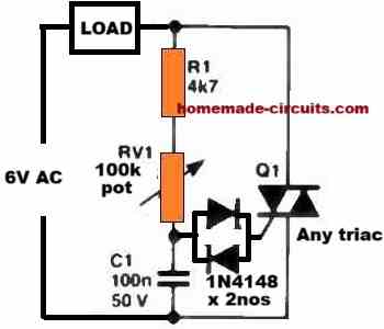
" rel="ugc">
Please let me know how it goes…
By the way, you can simply convert 6V AC to 6V DC and use a BJT circuit to control the bulb intensity, because the bulb can illuminate through both AC or DC supplies?
When I build AC light dimmer, the VR also gets heated. Is it normal and the VR will not be damaged in the long run?
No, that’s not normal, the VR has series resistors connected with it so it should not heat up at all, please check your circuit connections again.
hi swagatam,
I notice a issue with the conventional fan dimmer those are avilable in market , that has a triac in it , that when I connect a voltmeter (robu model : AD16-22FVA) at the output of the dimmer and take it to 0 position , the voltmeter shows 303v instead of 230v mains, also a resistor designed to work internally with the voltmeter makes a humming noise and after running the circuit for 2 minutes burning smell comes from the voltmeter, the voltmeter is absolutely fine but I dont understand this abnormal behaviour, here I have made a video album to show the same issue . link – https://photos.app.goo.gl/Kj1cQXsRSsB8Y9qEA the first video is of the dimmer in 0 position . the last video is the situation if i used the item with dimmer 0 position for a longer time, I have used a same item but another one just to confirm that my video item has no issue. its exactly same there also
Hi Preetam,
Did you try measuring the voltage with a incandescent bulb connected? Please try this, measure the voltage across the bulb.
Alternatively you can try using a moving coil type meter instead of a digital meter, or you can try a true RMS type voltmeter.
The issue could be because the dimmer chops the AC voltage to create abnormal waveform which may not be compatible with standard DMMs.
yes sir if I connect the bulb the voltage shows ok , but as soon as I removed load the voltage is abnormal + a constant humming sound always comes , might be this is due to the uneven waveform created after chopping voltage by dimmer .
In that case the problem may not be with the meter, it could be something to do with the loading of the triac. When the triac is loaded with the bulb, it could be stabilizing the triac conduction and the waveform.
The actual problem can be perhaps diagnosed by checking the waveform pattern through an oscilloscope connected parallel to the voltmeter.
Hi Mr. Swagatam;
Re. to above simple AC light dimmer circuit;
Is it possible to use a bridge rectifier diode as the load and having the dc 84V as the output voltage?
Hi Suat,
Then the average voltage will be 84V but the peak voltage can be 310V, which can be dangerous….
Is it possible to mention about the danger details. For instant shocking hazard
or overheat danger at high voltage side or disharmony between the ac and dc side
or faulty for the device to be used as the load or similiar?
Regards
The danger will be to the load and also to human being.
If the load’s working voltage is 84V, it cannot tolerate a peak of 150V or 200V etc and will quickly get damaged.
The high peak voltage can be dangerous to human beings also.
Hi Mr. Swagatam;
While the load is 220V 100W bulb and circuit is set to the highest level, my multimeter shows the voltage value between 197V and 212V. But oscilloscope shows 228V as the RMS voltage. So in this situation, is it possible to say that multimeter shows the correct value since the load is attached?
P.s: Simple AC light dimmer circuit is subject
Hi Suat,
Since the pot is at the maximum position, the voltage across the load should be almost equal to the input AC level, which should be around 230V, so, 228V appears to be the correct result, by the oscilloscope.
Hi Mr. Swagatam;
Multimeter gives the value between 184V and 220V at the output of the simple AC light dimmer circuit when the pot is rotated from lowest to highest value.
But It is not possible to see any different / various value on the the oscilloscope display even the pot is rotated to low or high position. I always see te fix / same value like : min-328V max 324V avg -4.00 v rms 231V vpp 652V vp 328V.
Is that normal or there is the point I miss?
Hi Suat,
Please connect a 220V incandescent bulb load in series, and then check the response. The waveform will clearly indicate the working of the dimmer.
Make sure to connect the scope across the bulb.
I have a few questions about the Improved Design, the 2nd from top. In the image it has a 47uh choke and in the parts list it says it is a 40uh choke. Which is it? Also, should it be an air wound or ferrite core?
I also see that the Triac in the image is a BT139 but, in the parts list it says a BT136. Which is it suppose to be?
Last is the .022uf 250v capacitors. Is there a specific type that is recommended like (Metallized Paper type) or (Poly Film type)?
The inductor value is not critical, the higher the better. It can be an air core or ferrite core, or iron core, its the inductance value that matters.
The triac can be any triac, depending on the load current and the supply AC voltage spec.
Capacitors can be metallized polyester or simply PPC type.
Thanks for the quick reply. I figured I would try this out and wanted to make sure I did`nt get the wrong type of capacitors. I will wind my own choke/inductor. My plan is for a variable temp. soldering iron using a cheap 50 or 60 watt 120vac iron. Thank you!!
Ok, thanks for your feedback! All the best to you.
Hello sir Swagatam, is it possible to ask for a copy of how you solved for the values of the components of the circuit? I am a student and I am tasked to build a similar circuit as yours, with given specs for the AC input and lamp, for a project, but I don’t know how to start. I would like to self-learn how to do this circuit from scratch, by solving the values of the resistors and capacitors. Thank you and sorry if my request is too heavy.
Hello Kai, I understand that you want to know the calculations details of the above circuit, however calculating the RC parameters can be quite difficult because there’s no easy formula to calculate them with a 220V AC parameters. I got these circuits from other online sources.
However, I can approximately tell you the functions of each of the parts. In the first circuit, R1 provides a fixed dimming value for the lamp in case the 220k pot is rotated to its minimum range. This ensures that the bulb does not shut off completely at this minimum range of the pot, otherwise due to hysteresis the lamp may not illuminate until the pot was turned at around midway. You can select R1 so that even at the minimum pot rotation the lamp gets the minimum glow on it and does not shut off completely.
The capacitor C1 also interacts in the same way, its value must be selected so that when the pot is rotated at its minimum range the lamp reaches its minimum glow and does not shut off completely.
R2/C2 decide how soon the diac must be fired again determining the minimum or maximum illumination of the lamp at a certain pot rotation, which allows the diac to be fired with consistent short burst of voltage instead of a abruptly switching pulses, which in turn allows the triac to be fired with smoother transitions, causing minimum transients and spikes.
Thank you for the response sir Swagatam! I would also like to ask how you chose the diac and triac for the light dimmer circuit. Can any diac and triac be used? And is it correct that I should base the values of the resistors and capacitors with the datasheet info of diac and triac? thank you again.
Hi Kai, the diac can be any diac, but the triac’s amp rating must be as per the load specifications.
Although the resistors provide the required protections to the diac and the triac, their values are mainly dimensioned for controlling the firing angle and timing of the diac and the triac.
Hi Mr. Swagatam;
I have input 120V air fryer but our main voltage value is 220V AC.
Is it possible to use that home appliance by using above dimmer circuit.
Regards
Hi Suat,
No, that is not recommended, because although the dimmer may provide a 120V RMS, the peak voltage can still be around 220V, which can be detrimental to the appliance.
so could you please advice a converter circuit 220AC to 120AC if possible.
Suat, Actually, your air fryer is a resistive load, so yes you can use a triac based dimmer circuit to convert the 220V to 110V, it will do the job.
thanks for the support, is it possible to use buck converter type circuit instead or which one is better dimmer or buck converter.
Buck converter is always better but for resistive load you can use a dimmer circuit. I currently do not have a 220V to 110V converter circuit with me, so unable to provide it to you.
Hello, and thank you for sharing your circuit designs.
I’m trying to build the “improved” AC Light Dimmer (2nd design above), I ordered the parts and now I’m in the phase of creating a layout for a piece of stripboard, using “DIY Layout Creator” software.
You can see my tentative layout here: https://ibb.co/k841cQ8
The green wires are my vertical connections, I think they’re OK, but I’m not sure about the small pink wire connecting 2 pins of the potentiometer, maybe it’s useless?
There are 3 trace cuts, the one next to R4 is useless for the moment but I plan to add a switch to the circuit so I added it to not forget…
I could avoid making 2 trace cuts and 1 wire soldering by connecting directly R3 between C2 and C3 horizontally, I suppose. I might do that if I find the horizontal space in the final design.
The BT139 TRIAC has its Gate leg on 3rd strip starting from the bottom, connected to the DIAC then through R4.
So I guess everything’s OK but I want confirmations before soldering it since it’s my first stripboard project…
Can you also confirm that I could connect a switch where I put the green arrow?
Let me know if you see any error, especially regarding the values of capacitors, resistors or anything. Thanks!
Hi there, Thanks for posting this question! I will try to solve your query, however, the link that you sent simply refuses to open in my chrome and edge browsers. The ibb.co website always throws this problem.
Could you please use some other image upload website and send the link here again? I will try to figure it out.
Hi again,
Ok, I could open the image in the TOR browser.
Let me check it.
I will let you know if there are any issues in it….
I checked the design, and I could not find any issues in the design, everything seems alright.
Yes, you can put the switch across the indicated positions, make sure to cut the track in that position.
Thank you for your answers, it’s appreciated!
Some modifications: " rel="nofollow ugc">
Do I need to keep the pink jumper wire or can I remove it?
I’ve inserted a SPDT switch as you can see on the image. I don’t think trace cut is needed with this configuration, am I wrong?
Thanks again.
Trace cut is required between the yellow wires otherwise the switch will not work.
Pink wire can be removed, it is not required.
Of course, I had not thought that without trace cut the switch would be rendered useless 🙂 Lack of sleep I guess…
You can use the final compact layout for veroboard/stripboard on your site, if you want: " rel="nofollow ugc">
Thank you for your time, bless!
Thank you for the feedback. Sure, I will use the new diagram in the above post, I hope the readers will like it.
Hello, I made some corrections because trace cuts were needed between the legs of horizontally mounted components (L1 & R3), otherwise they were simply shorted.
I’ve also attached the potentiometer and switch on a box chassis to make it more usable, so they’re connected to the board only with wires.
Please find the updated layout here: https://imgur.com/a/DODvzjN
Have a nice day and thank you for sharing the layout.
OK, Great! Thanks for the updated diagram, it looks much better now.
Hi Swagatam;
I tested above circuit with the parts BTA41 600 and 500 K pot and 100n capacitors (instead of 0,022 uF) thru both 800 watts and 2200 watts grinders. Speed control sensitivity was fine for the 800 watts grinder but that was not so sensitive for the 2200 watts grinder. However all parts were nicely cool not overheated.
Please advise if i should change the only 500 k pot with smaller value or also change the capacitors to gain sensitivity for the higher power equipment?
Best Wishes
Hi Suat,
the wattage of the motor should not matter, because both the motors are working with the same voltage that is 220V. The dimmer is controlling the speed by controlling the voltage supply to the motor, so this should work identically for both the motors. Changing the pot value or capacitor value are not relevant to the issue so it won’t work. All since the triac is not heating up that means the dimmer is not working with any kind of overload or stress.
You can try connecting a 100 watt incandescent bulb parallel with the 2200 watts motor and check the illumination of the bulb, if the illumination of the bulb changes that means the dimmer is working correctly.
Hi Swagatam;
I have tried the above circuit but both of them; either 100n capacitors and 10n capacitors were tried instead of the capacitor 0,022 uF. Load was a drill motor (220 AC 400 W). Drill works but 500 K pot does not control the speed. It is possible to say some critics about this situation?
Best Wishes
Hi Suat,
check the response with a 220V incandescent lamp first, that will give you a clear idea regarding whether your dimmer is working or not. I have tested all these circuits and they all worked for me nicely.
Try with a 220L pot or two 100K pots in series.
OK Swagatam;
I rebuilt the circuit and it works now. Sorry for my mistake.
Thanks
No problem Suat, all the best to you!
Hi Swagatam;
Ref. to above part list of the light dimmer, please advise about the followings;
1- It is possible to use 2 pcs of 100 K pot in a serial connection instead of 220 K
Pot?
2- It is possible to use 100n capacitor instead of 0,022 uF capacitor?
3- I will use BTA41 600 instead of BT136 so it is possible to add a any part as a fuse to protect the BTA41 or I should use a short circuit protection circuit before the main circuit or just adding i.e 30 A fuse to the circuit is enough?
Best Wishes
Hi Suat,
1) Yes, 2 pcs of 100 K pots in series will work.
2) 100nF capacitors might create problems with the minimum adjustment range of the pots. The load may reach minimum point (0V) before the pots can reach their minimum rotation level. As a rule the load must never reach the 0V point otherwise it might not start again until the pots are rotated far down midway. However you can try 100 nF and see how it works, if it has problems you can connect two 100nF in series to make 0.047uF capacitors.
3) A fuse would be a better option. So you can connect an appropriately rated fuse in series with the input supply line.
all above are great info for me thanks Swagatam and also I have deduced from that you advised so the 2 pcs of 10n capacitor in a parallel connected would might be better? I need your confirmation.
Best Wishes
It’s my pleasure Suat, you can use two 10nF in parallel, but if you find the heater not reaching minimum level with these capacitors when the pot is moved to minimum, then you can add one more capacitor in parallel or until the heater level is able to reach its minimum heat, but not zero.
Hi Swagatam;
Fortunately I found a triac p/n: bta41 600b in the scrap pcb parts. However there are 2 circuits at the above topics which are one with the triac tic226 and other one is with the bt136 (with the header as improved). I will use my bta41 in the circuit instead of tic226 or bt136 but which circuit you would advise the one light dimmer with tic226 or other with bt136.
Best Wishes
That’s great Suat, Glad you found it.
All the circuits can work with the both the triacs, in fact with any triac, so no issues.
I would recommend the circuit with the PCB design or the following one or the last one, all these 3 designs are tested ones:
" rel="ugc">
Hi Swagatam;
In the market I am able to find BTA16 / 800 instead of TIC226. It is possible to use that kind triac for hair dryer dimmer circuit or does that double parallel connection of BTA 16 on an aliminum heat sink is remedy?
Best Wishes
Hi Suat,
I think TIC226 should also work. According to the datasheet of the IC, its maximum voltage and current handling capacitors are 400 V and 8 amp respectively. Triacs cannot be connected in parallel, so you you cannot connect them in parallel.
Hi sir., Pls clarify whether the triac or diac in the first simple triac dimmer circuit needed any dc voltage for their activation. In the circuit diagram, no such sources are shown. But you have mentioned about dc voltage for triac in the comments section. That’s where the confused arises. Also I’m really confused with the connection of ac load. As far as I understand, the phase of ac should be connected to MT1 of triac and the phase output should be taken from MT2 and then connected to load. The neutral wire should go directly to the ac load. Is this the correct way to wire the dimmer circuit?
Hi Binoj,
AC light dimmers are fully AC they do not require any external DC to operate. I cannot see any comment where I have said AC light dimmers require a DC to operate. As far as I know in AC light dimmers the load can be connected with any of the output wires in series. When you a buy a new AC light dimmer you find only two wires coming out from the unit, they never mention which wire is for the load, so the load must be in series with the any one wire of the light dimmer. There are no phase/neutral for this circuit, phase neutral can be connected anyway round.
Ok sir. Got it from your reply. Sir may also know how the 220kohm and 1k ohm resistor values are selected as such. Will the dimmer work if the pot is 100Kohm or 1Mohm? Is there any specific calculations for the resistor values? And one more thing sir, can I use an ldr to automate the working of the dimmer as per the light falling on the ldr? If so, how can it be connected in the circuit? I think ldr can work with ac also as it is a resistor . Thank you sir
Hi Binoj, The 220K pot value is selected with reference to the 100nF capacitors. Together they make sure that at the minimum position of the pot the load still gets some minimum amount of current and does not become zero. If it becomes zero then the load will not start on slight rotation of the pot rather will require the pot to be rotated upto midway, which is not good.
1K makes sure that when the pot is at the upper extreme position, high current does not reach the diac/triac gate. 1K limits the current when the pot is rotated to the upper extreme position of its range. Unfortunately I do not have any formulas to calculate these parts. You can try replacing the pot with an LDR to replicate light dependent load control.
And finally i assembled the simple dimmer circuit and happy to tell that it’s working smoothly. But when I changed the incandescent bulb to an led bulb of 9W , it shows some small flickering continuously. I used a 100k pot only as the 220k is not with me. (All resistors used was quarter watt. ) Is it a problem for the flickering sir? And one more thing i noticed is that the bulb doesn’t turn off fully at the extreme pot position. The output voltage when measured with DMM shows around 130/140volts only
even when the pot position is varied. Is it normal sir? Can I use the same triac for operating high wattage loads such as drilling machine or so? Does the circuit needs any modifications for high watt operation? And sir,is it good to use a glass fuse for additional safety in this circuit? Thanks so much sir for your great help..
Hi Binoj,
unfortunately LED bulbs being fully electronic cannot be used with triac light dimmers, they simply won’t work correctly. Light dimmers are intended only for fans, incandescent bulbs and heaters.
To reduce the load to minimum you will need a 220K pot.
You can control drill machines also with this light dimmer circuit but make sure the triac is appropriately rated and mounted on a heatsink. You can try a BTA41 800 triac.
And also make sure to use a 47 ohm resistor in series with the diac, otherwise the triac/diac might not last long.
Yes you can add a fuse to the circuit for additional safety.
Great page with great and useful information.
Good day Swag, is there any way we can modify dimmer to work for low wtt capacitance loads and inductive,?
Can transformer be used?
Thanks.
Hello Seun, the dimmer can be used to control a transformer, or any other similar inductive load. It can be also used to control capacitive loads.
I built the second circuit and it is working very fine both in lamp dimming and fan regulation. But I discovered that the digital AC voltmeter doesn’t get below 200volts and regulated to least possible voltage using the potentiometer even at the point the fan offs and lamp stop shinning, it is still reading within 200volts. The digital multimeter also does the same thing. But with analogue AC voltmeter, it works perfectly regulating to zero mark and maximum when regulated. What should l do to make digital meters read properly.
That sounds strange? Did you connect the AC digital meter parallel to the load? If the load intensity is reducing towards zero then the meter should also behave accordingly. I have so far not tested a light dimmer output with a AC digital meter so i am not sure why it may be behaving in that way?
The average RMS of the AC will reduce as the light dimmer generates the increasing chopped AC waveform. So technically the AC meter should be able to read this RMS voltage correctly upto zero.
Yes I connected it in parallel with the load just like I did with the analogue meter(which works fine), the ac digital meter did reduce and increase but surprisingly it didn’t reduce below 200volts even as the load becomes inert. I did the same with digital multimeter and I have the same result. I then bought the commercially available dimmer switch yet the same experience. I begin to wonder what must be the cause. I am stocked now because I needed to built ac voltage regulator in which the reduction and increment in voltage levels are visualized with digital AC voltmeter.
Sorry, I have no idea what may be causing this issue with the digital meter. Maybe it is related with the hum interference present in the AC waveform which may be causing the digital meter circuit to remain always activated
Dear sir,
Please sir, from the first circuit (simple light dimmer)
Will the circuit work if I connect the 24V from transformer output to the 220v mains supply to get 0- 24v from the L1 (light bulb)?
Or I should connect the 220V side of the transformer to L1 while the Mains supply remains 220V?
Hi Godfrey,
You cannot get 24V AC directly from the circuit, you should connect the 220V side to L1 points which will enable the 0-24V side to be controlled as desired.
Okay sir, thank you.
Please sir, how can the circuit be modified to get Ac dimmer for 50VAc load?
Because I wanted to vary the voltage of one winding of the transformer outputs to use on the variable power supply you have helped me built, while I use other windings on their rated voltages at 220V mains input for other circuits
Hi Godfrey,
You can use the first circuit for controlling 50 V AC also. However, you may have to change the RV1 pot to a 100K pot
Okay sir, thank you.
It has worked for 50V, though the only issue now is that the voltage is fluctuating much.
However, I have seen ur circuit on the article: “Voltage Fluctuation in Triac Phase Control Circuits” but the UJT transistor and 1:1 pulse transformer are not handy.
Please sir, is there any substitute for the two components or another circuit design that can solve the fluctuation issue?
Thank you for your reply.
Hi Godfrey,
Is the fluctuation happening with 220V also?
I guess the fluctuations could be more visible for the low voltage AC control only.
You can try replacing the pot connections with an equivalent fixed resistor and check the results.
Unfortunately I think this cannot be controlled at the AC side, you will have to correct this at the DC output side using a filter capacitor.
No sir, I didn’t check with 220V.
I will confirm it.
Thank you very much sir
Sure, no problem!
Hi Swagatam;
Regarding the above improved light dimmer diagram, I will add also BT136 switch on the point between AC mains input and AC Motor as serial connection. Please advise if that location is proper. Thanks and regards.
Hi Suat,
 " alt="how to add a triac switch in series with a triac dimmer circuit" />
According to me it should be added in the following manner, but I am not sure about the results:
Thanks too much for your kind response Swagatam.
Gate of the switch will be loaded by DC 5 Volts not AC. In fact + 5 Volts will be present all time on the gate of the BT136 switch but as soon as PIC sends the +5 Volts to the base over a NPN transistor then (-) from emitter will fulfill the circuit. I will write the result. Regards
You are welcome Suat,
OK I understood now. I hope you will be able to configure the 5V circuit with the triac. By the way, in the above diagram, there should be a resistor in series with the switch and the gate, which I forgot to add. Let me know if you any further questions.
My questions at the phase Swagatam;
In fact if relay was proper for the purpose of egg incubator heater then it was easy circuit but I think relays will be damaged under such frequently conditions.(frequently opens/closes in a minute) However, If possible to use BT136 like transistor, then I simply immerse the BT136 to the dimmer circuit otherwise to my inefficient knowledge, that may be trouble. Neverthless, I will try all alternatives. My other question is it is possible to change capacitors values. Many thanks and Regards
You are right, an AC switch using triac will be more efficient than a relay switch since relay switch can be prone to physical wear and tear. The C2, C3 capacitor value can be changed to some extent, but not too much.
Hi Swagatam;
I need your support on the followings.
1- I did test the BT136 and applied DC (+) 5V to gate and (-) to MT2 but did not happen short contact between the pins of MT1 and MT2. Is that normal?
2- I met the MOC3021 while the google search the so please advise if it is better to use that one as a switch instead of BT136 on the dimmer circuit?
3- However, I have in my stock 4N25 please advise if it is equivalent instead of MOC3021 for the AC circuits?
Kind Regards
Hi Suat,
I already doubted the previous method of connecting two triacs in series, because triacs or SCRs do not work correctly when added in series.
Yes MOC3021 is the perfect way to implement a triac switch circuit.
No, 4N35 and MOC3021 are two completely different opto couplers, they cannot be interchanged
Hi Suat, I think even MOC3021 might not work for switching a triac dimmer circuit ON OFF because the MOC IC also consists of a triac and the dimmer also has a triac, so the two triacs cannot be put in series.
That sounds only way to change the heating resistor with the proper one. Many Thanks
You are welcome.
Hi Swagatam;
I am interested to use the above improved light dimmer. C1 is optional and I think that sustain the output values. Please advise if input is 220 V then it is possible to use 0.1u/250V instead of 400V and my other question is if I may use not VR but ordinary resistant for instant as 330K to gain constant output? Meanwhile I think the resistant lower than 220K is not proper for the circuit. Thanks and regards
Hi Suat,
The 0.1uF capacitor complements the 40uH inductor and they both together help to suppress the Rf noise generating from the light dimmer. If you use the inductor then you will have to use the 0.1uF capacitor also. For 220V input it is not safe to use a 250V capacitor because if accidentally the input voltage rises above 250V then the capacitor might explode, therefore it is recommended to sue a 400V capacitor.
Instead of the pot VR1 you can use a fixed resistor to get a fixed output control….any resistance between 1K and 220K can be used in place of the pot VR1, however you must not change the values of the 330K and the 15K.
Hi Swagatam;
There is an coil 40 uH optional at the above circuit. That is some kind of filter or booster or something different? I have a friend who is scrap owner I can find 40 uH there, it is possible to use coil at higher or lower values? Thanks and Regards.
Hi Suat, As we know that a triac based AC dimmer employs phase chopping which creates a lot of RF noise, and this noise can create disturbance in nearby radio receivers. Therefore the coil and the parallel 0.1uF capacitor are used to suppress this noise generation from the dimmer circuit. The coil value is not critical, you can use upto 100uH. You can even build it at home by winding 100 turns of 1 mm thick super enameled copper wire over an iron bolt.
After reviewing a lot of info from ST Micro on Triac’s like 7 articles on associated material I think I have to position the load on the positive rail. I hate this because of continuous energized load. not so on the negative rail but it then can not be implimented or controlled in all four quadrants. I am more confused now then ever and that stinks. I need more material before I will commit to one set design.
again thanks for your help Swagatam
Thank you Doanld for all your dedicated efforts to build this circuit. I wish you all the best and hope you are able solve the pending issues and succeed with the project soon.
Thank you so much. Sorry I am still wanting some isolation though so I think I will add an MOC 3053 between the RV1 and the junction of C1 and R2. this will work right? just for clarification. for some reason I do not like that diagram you mentioned, like it is rubbing me wrong. I am still accounting for resistive as well as inductive loads so additional parts will be added so the board will be universal.
Many, Many thanks Swagatam
You are right Donald, a MOC opto must be used in the middle. Please ignore my previous suggestion.
Swagatam,
Yes I am aware of what you had stated. what I was referring to is the specific triac in the above replay that is intended to be interfaced directly to microcontrollers, logic integrated circuits and other low power gate trigger circuits. WeEn Semiconductors BT139-800E 800 v 16 A is low power control so could you design somethin to reflect this low power control or do I do PWM directly with Micro controller.?
OK, so you are looking for the wiring diagram to interface triac with microcontroller, right?
You can apply the PWM directly to the gate of the triac through a resistor, and configure the triac as indicated in the first diagram from this article:
https://www.homemade-circuits.com/simple-triac-triggering-circuits-explained/
PS. I found out that zero crossing can not be used for phase controlled triac circuits so new parts were placed on board.
Thanks a million.
Hello Swagatam it’s me again.
We had talked about PWM using an arduino and a voice activation circuit. the Triac I am thinking about using is a WeEn Semiconductors BT139-800E 800 v 16 A which is sensitive gate “series E” triac is intended to be interfaced directly to microcontrollers, logic integrated circuits and other low power gate trigger circuits. this changes the circuit considerably. so I was wondering if you might help out a little with me reconfiguring the circuit to minimize parts. Yes I am still snubbing the parts because the board will be universal for resistive as well as inductive loads.
Many, many thanks in advance
Hello Donald,
are you trying to find out how to configure triac with Arduino? I can show how to do it. PWM dimming can be used with AC triacs also. In AC we have 50 cycles passing the zero crossing in one second, if we create breaks after every one cycle or two cycles or 3 cycles, we can cause different levels of brightness on the connected bulb. However the bulb must be an incandescent bulb not an LED bulb.
Please how can I modify Elkor design to dim 3kw load
Awesome!
Finished two board designs last night, one with multi-resistors and the other PWM from Arduino. sending them off and purchasing voice control module. i will test then report back which is best.
Regards,
Donald
Great! Thanks for the update, hope the final circuit performs as per the expectations!
All i wanted to know if it will work (Thank you). i have the Arduino side covered and with the use of a Voice Activation module V3 and programing. i will be able to control light output with a triac based opto coupler at each resistor. I am sure some testing will be at hand to get the right resistor values but overall feasibility is good. what i am looking for is when i walk into a room i can say light 50% or what ever brightness i need or light off. cool huh !
when finish my board design then test it i will report back to you with the finished product so you can post circuit here for other to share in the fun.
That sounds great! Hope you succeed with the idea, then I can post a new article on this!
Hello Swagatam.
In the circuit above with the incrementing resistor the use of opto isolators or small cheap triacs in between the different resistor values will allow this circuit to be connected to an Arduino and a voice control module which will allow changing of luminosity of the light with voice control.
off
100%
75%
50%
25 %
is this correct or what device do i need between resistors and R3 ?
PS. thank you so much for your time and patience and for this web page
You are welcome!
Hello Donald, I guess that may be feasible if a triac based opto coupler is used, as shown in the following diagram. However, since I am not good with Arduino programming I may not be able to provide much help on this.
" rel="ugc">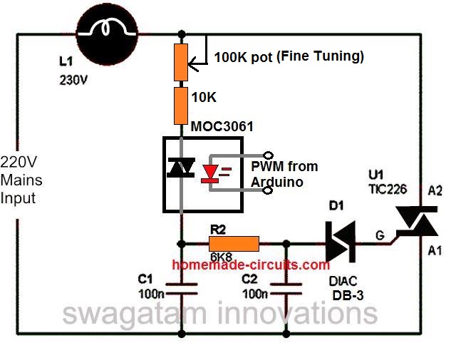
Hi Sir, I will like to ask is it possible for me to add an LDR to the SCR light dimmer so that it can function automatically? If yes where should I add the LDR? Thank you.
Hi Karina, how is it supposed to function, day time ON or night time ON?
night time ON
In the first circuit connect the LDR parallel to C1.
What if I have to use SCR in the circuit too?
Do you want LDR with SCR for the switching?
Yes, I will like to make an automatic SCR light dimmer. Is this possible?
The LDR can be controlled with anSCR, but the triac cannot replaced with SCR for light dimming, it will not work properly!
So where should the SCR be connected?
I cannot understand your need, do you want ScR to control the day night ON/OFF, or to adjust the dimming of the light.
Please explain correctly.
I will like to build a SCR light dimmer circuit and I thought off adding an LDR to the circuit so that the brightness of the lamp can be controlled automatically by the light intensity in the surrounding but I’m not sure how should I connect the circuit. Is it possible to build such a circuit? Thank you.
If you use an SCR instead of triac then you will get 50% light only at full brightness, because SCR cannot conduct for both the AC cycles, so SCR cannot be used in this application.
Good day Sir, I have been using your dimmer circuit for a year for my motor but when I recently added a low value resistor at the Ac input to further limit the current. But I found out the dimmer is not working again. Please what could be wrong Sir.
Seun, the dimmer might have been destroyed due to motor transient not because of the resistor. Try changing the triac with a heavier one and see if that helps. Use triac with in-built snubber
Thanks Chief Swag, I used the dimmer circuit for many gadgets and worked well but for freezer, Tv, laptops there was increase in power consumption rather than reduce, what’s the reason.
Hi Seun, I can’t figure out the exact reason, however dimmer circuit is not recommended for inductive or capacitive loads….you must try a variac instead.
Thanks Sir, which ones are capacitive and inductive load, please how can I do variac
Freezer is inductive load, TV, laptops are inductive/capacitive both, Varaiac is an autotransformer, please check online you will be able to find a lot of information about the device.
Please which kind of load is water pumping machine
All motors based devices are inductive loads.
hi, I am recently DIYing a lighting source over my desk, and I bought a LED COB 50W, that are called Driverless LED, so this Led type can to be connected directly to main AC 220V.
My issue is the dimming part: I also got an PWM 200W dimmer or Voltage regulator for Motor
When I try to dim this led with those dimmers, the light is fluctuating a lot.
I read that it is not an easy task to dim Led light source. Maybe because those dimmer are dimming/variating voltage, and to dim Led it is better to dim current (AmpS), that it is what infos, I could gather…
So any knowledge or tricks to can dim this 220v led, it ll help me.
Regards 😉
Hi, the dimmer that you are using is a triac/diac based dimmer which might not be suitable for LEDs, you will need a PWM based dimmer such as this one.
…The circuit is not isolated from the mains, so be extremely careful while handling it in an uncovered/powered condition.
Hi, I was searching for ” Humming free step fa regulator” in your blog but I couldn’t find one. Then I found the below two circuits through google. But am confused which one will be more efficient.
 " alt="hum less or hum free fan regulator circuit using capacitors" />
In Fan 1, Capacitor 1uf, 2.2uf and 3.3uf are used.
In Fan 2, They are mentioned as C1=2.2uf, C2,C3=3.3uf, but in circuit diagram it is mentioned as C1,C2=2.2uf and C3=3.3uf and Connections also different in both.
Hi, the electronic regulator circuit explained in the above article can be made hum free by appropriately customizing the L1, C1 values.
In your circuits, the fan2 wiring is not correct, and also it involves two contacts to be switched simultaneously, so I have deleted it.
Fan1 is correct, but the capacitor values are not critical, you can customize the values as per your requirement for the various steps.
1uF capacitor will produce 50 mA 220 V, 2uF will produce 100 mA and so on. You can adjust the values with trial and error and by adding or removing capacitors in parallel.
Resistor specs are 1/4 watt 5% CFR
Good day sir, please is there anyway to configure a triac based dimmer to make it produce pure sine wave out put. This is to put off the humming experience at low speed in ceiling fans.
Less I forget, happy new year sir!! I have not been seeing your updates for some time now. Hope all is well with you sir
Good day Moses, Happy New Year to you too!
The humming sound can be controlled by adding an LC filter as shown in the second schematic from top from the following article, using L1 and C1.
https://www.homemade-circuits.com/how-to-make-simplest-triac-flasher/
I keep updating new articles often although not as often as I used to do earlier, since I seem to have run out of new ideas and concepts.
You can always visits the blog page to check New projects.
For example you find values of r,pot,c how you find volues of r,pot,c i need formula and prove.
İn shortly Design a dimmer circuit Lamp work 200watt and write how you find values of R,C prove with formula and determine Diac and Triac model.
it is very important for me please design of this circuit may be like your design but how do we choose the value of the resistance and capacitor please inform us in advance.
Hi sir,
How can i do dimmer circuit for ‘200 watt lamp’ ? And which schematic is the best for me ? Please reply me.
Thank you.
Hi Omer, you can use any of the above circuits for your application, just make sure the BT136 is mounted of a large heatsink.
Thank you sir, sorry for asking but i’m not good at electronic where should i put the lamp exactly on second or third circuit ?
You can put the lamp in series with the wire which connects with the center pin of the triac in the second circuit…alternatively you can just buy one ready made fan dimmer, open it and check the details.
How to get zero volt? My circuit is always on give me 170v, 175v, 192v.
Make the circuit shown in the above article, you will get the correct results
I don’t want anything but congratulations for a wonderful site.
Hello Swagatam,
I am not getting the DIAC DB3 diode and 0.1uf/400v capacitor. Are there any best matches to use? I am only a hobbyist trying my hands on the circuit. thank you
Hi Isbn, you can probably try a 220v neon bulb instead and see if it works or not
Hi Swagatam nice of you to share your knowledge in electronics. Now I have an old AC-DC 12V power supply (the transformer type) that I would like to convert to charge lead-acid battery but the problem with this unit is the output voltage is too high ( 17.14 VDC ), so I am hoping to use your TRIAC dimmer circuit to reduce the voltage down.
I intend to tap the AC right after the step-down by transformer but I think the DIAC cannot work at such a low voltage. Do you have any idea to do this ? Thanks
Thank you Ananda, you can try applying the triac dimmer across the primary 220V side of the transformer and reduce the secondary side to 15V RMS. This might do the trick!
Thanks for the suggestion. However, I am trying to avoid controlling an inductive load like the transformer as you know it will be more complicated that is why I am trying to control the secondary side. Is there any other way of controlling phase angle of low voltage AC (~17vac) using Triac ? I am just a hobbyist in electronics. Thanks
Today most traics have inbuilt snubbers and are truly resilient to inductive loads, especially when the dimmer switch is built with some caution.
I have tried it myself and I could smoothly control a 5 amp 12V halogen lamp by controlling the primary side with a dimmer switch.
I have not yet tried a dimmer with 20V AC or less so I am not sure how it may behave, and there isn’t any other way of controlling this except triac/diac based concepts.
The last two circuits in the above article are specially suited for inductive loads as per elektor electronics magazine.
pls sir can I use the second circuit on a 950w generator to power a refrigerator of 1200w
Victor, refrigerators don’t like to work with phase chopped ACs, so I don’t think that would be recommended.
sir what do you suggest I do to make it work
What is your exact requirement?
is it the circuit requirements or the refrigerator requirements
What exactly are you trying to accomplish or implement??
Respected Sir,
I made above ceiling fan regulator circuit , but at low speed disturbing noise/hum develop in fan , please help me to suppress that noise/hum (at full speed it is fine ) .
Thank you
Deepak….
Hi Deepak, please add the L1/C1 network in your circuit and see if that solves the issue. L1 can be built by winding 50 to 100 turns of any thin transformer wire over an iron screw, size can be as per fitting
Hello ,
Can you tell me ho to calculate the inductance , and also if a shielded drum core inductor can be used or not
L1 and C1 act like RF noise suppressor and are actually optional, I do not know about the calculations at the moment, but it can be optimized through some trial and error. Initially 50 turns of 0.5mm magnet wire could be tried over a ferrite ring or rod, and then the number of turns could be tweaked for achieving maximum suppression.
L1 = 40uH (optional). What wattage inductor should I use? The resistor shaped inductor only handles 1/4 and 1/2 watt. Also standard inductor values are 33uh and 47uh. The old pellet style inductor can handle 1.5 to 1.8 amps @ 1KHz.
You can use any inductor built by winding 50 turns of 0.5mm magnet wire over any small ferrite core, I think the pellet inductor might work
Please sir, I tried out the second circuit above and I observed that when I connected a 1200w pressing iron to a 1.5kva generator, the generator started vibrating heavily and the sound of the generator changed drastically, but when I plugged the 1500w pressing iron to the circuit and plugged the circuit to the generator, the Vibration and the sound was less compared to when I plugged the pressing iron directly to the generator. please sir, what do I add or remove so that the sound of the generator does not change at all?
Chidi, it is simply because the dimmer is reducing the power of the load and allowing the generator to work under controlled load, whereas connecting the load directly is causing the generator to overload and vibrate….you must calculate the loading of the generator correctly and use an appropriately calculated load which will not cause overloading.
What’s the effect of this dimmer on the coil of the AC motor. Thanks
No serious effects
Hello sir Swagatam,
Thank you for this post. I have some questions:
• What kind of capacitor are C1, C2 and C3?
• By using the circuit with different values of resistors instead of a 220k pot to control a fan, which point will turn off the fan? Is it the point with the highest value of resistor (extreme left) or the point without any resistor? (extreme right). At what point will the fan spin fastest?
Hello Godson,
All capacitors are PPC type or MKT will also do.
The extreme right point will give the fastest speed, the extreme left is supposed to give the slowest.
Ok sir. Thanks a lot for the prompt reply.
So I suppose that if the arrow (in the diagram) does not touch any of the points, the fan will not spin at all. Am I correct?
yes that’s correct, the load will not operate when the arrow head is not connected to anything.
I used it with electric iron. It worked well, but failed later. I used bta 41/600b triac.
did you connect heatsink with the triac?
Yes, please what else can I do
I think your triac may be duplicate in quality, an original BTA41/600V triac will never get damaged with a resistive load unless the ampere rating goes beyond 40 amp….buy a new triac from a reputed online store. and check again
Thanks, the circuit worked but after some time triac failed. How can I protect the triac better.
where and how did you try to use it?
Sir,
I would kindly ask two clarification:
– the value of C3 and C3 is 0.022 uF? (on the page is stated only “0.022”)
– the voltage value of the capacitor (C1, C2, C3) stated as 400V and 250V is refered to the voltage AC or DC?
Thank you very much.
Stefano
Stefano, C2, C3 values will depend on the value of the pot used, for a 470K pot you may use around 0.022uF/250V for these caps, and for lower value pot such as 220K, the C2/C3 values could increased to 0.05uF or even 0.1uF.
There are no AC or DC capacitors….the voltage value on capacitors denote the maximum peak voltage the capacitors are rated to handle, regardless of whether it’s AC or DC.
Please can these work well with TV, I had two dimmers that have spoilt my TV
Sorry I could not understand how a dimmer switch could be used with a TV, please elaborate.
Good day sir thanks for your help and support. Sir plz I tried your circuit and it worked, but for some time I noticed some sort of flickering and i think it could be from the diac firing so I replaced it but continue again for a very short period of time I even tried connecting a 100ohms resistor in series with the diac but it didn’t work. Plz sir how can I solve the firing issue of the diac. Thanks
Gift, as you can see in the video, the bulb does not flicker at all, I think there could be some fault either in your diac, capacitor or the pot, please make sure the parts are of good quality then there won’t be any flicker.
Is the triac bt136 or bta 41/600. Can this work well with television. Thanks
both will work depends on how much current you may want at the output….
hello sir, the R1=15k gets very hot(turned black) with 1,500W load, what can i replace it what for better handling capacity. thanks.
bayo, R1 has nothing to do with the load, so it shouldn’t become hot under any situation, I think something may not be correct in your circuit, please check it properly.
Hi, with soldering iron you won't be able understand the response, you should use a 100 watt bulb instead, however with 0.1uF and with 500K pot the output might show sudden shut down at some lower pot limit…therefore you must match the parameters such that the lowest pot adjustment does not allow the output to fall below a specified minimum voltage level
Hi Swagatam.
Thank you for the nice post, and for keeping the thread alive – awesome 😀
I'm looking to build a dimmer-box to mount on the ceiling next to a chandelier. I just want a rotary knob on the box to be able to adjust the light level, so no fancy/smart stuff..
The chandelier has 5 LED bulbs (4W each) which all include the needed circuitry to allow for dimming (supplier specified a SCR-dimmer).
Do you think I can use the second schematic from your post without adjustments?
What size resistors would you recommend? 1W or larger?
Would it hurt if all capacitors are 500V?
Do you have any suggestions on what variable resistor/potentiometer to use?
I'm looking to use either BT136-600E or BT136-800E – any recommendations?
Where should R4 go? The one next to the diac?
Sorry, but I'm a bit of a noob in electronics 🙁
Thank you Kenneth,
Why don't you buy a readymade dimmer switch instead of taking the risk and time of building one, unless you are doing it as a hobby?
yes second schematic will do, the first one will also work.
however I have never seen a triac based dimmer switch being used for controlling LED modules.
the circuit indicated in the above article will not need any kind of changes for upto 200 watt 220V applications, so for your requirement also the same circuit could be used.
BT136 600, or 800 both are fine.
R4 should be where it is shown in the diagram, behind the diac.
all the resistors are 1/4 watt….L1 and C1 are optional.
If you are a noob then you should prefer buying one ready made, ceiling fan dimmer-switches are quite cheaply variable in the market….just a couple of dollars.
Hello Sir and thanks for your efforts, you site is highly educational. I built the second circuit, but get little variation between both ends of the variable resistor, both with a light or a 300w motor. I did not have all the components as recommended, so I am using a 500k variable resistor, a 68 uH inductor, the triac is an sc146d, the 33k resistor is made of paper and pencil lead scribbled on it. The 0.022 uf caps are 400v not 250.
do you have any suggestions? thanks in advance
Thanks Mark, C1 and L1 are not relevant, so those are not responsible for the full phase control.
the capacitors, the pot and the resistors are the components which are actually used for the phase control.
try increasing the values of the 0.022uF to 0.044uF each and then see the difference, if still there's no difference then definitely there's some other serious issue with your circuit, in that case you might want to replace the diac, or the triac or the 33K etc.
Thanks for your reply, I've been tinkering all day with it, it seems I get the same rpm out of the motor with no load on it, but the power is lower, as if the circuit is actually decreasing power instrad of rpm. I need this for a lathe, so I need strong slip even at lower speeds. Not sure if I am making any sense, not an expert here…thanks!
whether with load or without load, the motor should respond from minimum to max speeds when the pot is turned to and fro.
the best way to test it is with a 100 watt lamp, if the lamp is not dimming from zero to max and vice versa, then definitely your circuit has some fault.
Thanks, I need to male sure I am reading the second schematic correctly. Are all intersections also connections? I wired as such on my breadboard, but maybe I should not have connected something to something else
breadboard is strictly not recommended, please build it again by soldering the parts on a veroboard.
wish you all the best!
Hi, ok created a pcb, not working. I really need to know if designing the schematics you followed standard rules in the matter of crossing lines. Usually when crosssing lines have a dot on them they are connected, otherwise they are not, or show a little bridge line. Are yours connecting at intersections or not? Thanks
There's only one intersection above C3 and that's connected.
Hi again, it works fine with resistive loads and single phase brushed motor, however I cannot regulate a brushed universal motor, I can only increase speed but cannot decrease it afterwards. Have to switch it off then lower pot to min then switch on and increase to whichever speed desired. The motor has three coils and two brushes, with ac mains going in one brush on one side and one coil on other side, while the other brush and one other coil pin are bridged together.
Hi, sorry can't figure it out…The circuit works perfectly with ceiling fans which have capacitor start motors, not sure why it's not working with your brushed universal type motor…somebody having expertise in motor electronics would be able to diagnose this correctly.
Interesting…fan motors are induction ones and can usually be regulated with variable frequency drivers only. thanks all the same
Dear Swagatam
Nice to say hello, I have intentions to use the circuit of the second image, this would help me to control engine speed from a desktop drill press Black & Decker 1/3HP – 250W.
Regards
Hello AlFaFer,
yes you can use it, just make sure the triac is appropriately selected as per the motor current specs
the application can be solved using PWM, along with a MOC3063 optocoupler circuit
I was referring to a LED bulb unit, which includes a switching driver inside and therefore it has to be a capacitive/inductive load….if it would be only a LED then the issue would be different.
Actually, the circuit will work with LEDs, but you need to make a modification.
LEDs are *** NOT *** capacitive (beyond a few picofarads) or inductive loads. But they ARE DC devices. If you use them in an AC circuit, you'll only drive them about half the time. So instead of driving the LEDs directly, drive a rectifier bridge and use the rectified output to drive the LEDs. Note that the voltage drop across the LEDs must (reasonably) match the source voltage. If you stick a 1.3V LED in line, all the smoke will leak out. There are LEDs in the 20W to 100W range with forward operating voltages in the 25V-30V range. If you're on a 120V circuit, putting ~4 of these in series will give you the correct voltage range. If you're on 220V power, you can use ~8 in series.
Note that LEDs are about 7-8 times brighter than a corresponding incandescent lamp of the same wattage. This means you can do cool things like replace a 500W bulb with 4 series 100W LEDs and get the equivalent of 2800-3200W incandescent… good for outdoor flood lights… 6 times the light for 20% less power. I'm in the process of replacing my INDOOR torchiere halogens with 4 series 20W LEDs. At 100 lumens/watt, that will give me about 8000 lumens… about the same as a 500W incandescent. Not only that, but the LEDs won't heat up a room like a 500W incandescent or halogen!
If you want to get fancy, you can even adjust the color temperature by using various combinations of LEDs… maybe a couple soft with with a couple cool white. Or a red or green LED with 3 cool whites.
Do
*****NOT****
use a series resistor with the LEDs. That's just wasted energy. For example, if you wanted to run a 20W LED from 120V power (assuming a 30V forward voltage), you would need to drop 90 volts across the resistor. Since the LED will need to draw .67A for operation, your resistor would have to be about 135 ohms – meaning you'd dissipate nearly 60W in the resistor – three times what your LED is using (which would reduce light efficiency by ~75%). You might as well use a halogen.
If you only want to drive a small module (not multiple 20W+ units) then your best option is a step-down transformer.
Dear sir, what do we use two triac in parallel
please open this link
https://lh3.googleusercontent.com/-Zmd8tb6ZFJk/V4TjgDBIL7I/AAAAAAAAAVI/i7VwyLKr22orSL7MQuVov2uS0zXmga2Tw/w1060-h532-p-rw/2016%2B-%2B1
Dar Rakesh, Your image is not opening correctly….
triacs cannot be connected in parallel due to technical constraints…
ok thank you sir
Dear sir,
300 turns ok kindly provide Lead Diameter and Inductance value
Thank you
Dear Satheesh, 300 turns is OK, the wire diameter can be a 25 SWG or similar
Dear sir how to operate MOC3021 direct by 220V AC please help me for this circuit
https://lh3.googleusercontent.com/AWaovahfmGaL0SzJU-U4JqBdBCThiTi5VsPeE451TrOfereJ7ZEM_3Zply0BkNdi4Aweqa1T1w=w1440-h2560-rw-no
converter the 220V into 5V through any adapter or a cell phone charger, and use this 5V DC to operate the second 555 circuit from this link
https://www.homemade-circuits.com/p/ic-555-calculator.html
replace R1 with 10K, R2 with an LDR, and C1 with 1uF.
feed the pin#3 and the negative line of the circuit to the LED pins of the MOC.
Dear sir ,
Good day to you . I have used above the Triac Dimmer Switch I can regulate the ceiling fan At the moment it got little bit of noise from fan. How can I regulate the fan speed smoothly without noise?
Thank you
Dear Satheesh, use L1 with higher number of turns, wind it over an iron core such as an iron bolt or rod. use around 300 turns or more
make sure the 0.1/400V capacitor is not faulty.
sir please i need a guide on how to assign values or calculate values for the potentiometer, resistor and capacitor.. like an analysis
Dear sir अपने first circuit बोला है पर उसमे TRIAC TIC226 लगा हुवा है और मुझे BTA41 लगाना है तो क्या मैं उसकी जगह BTA41 लगा सकता हूँ कोई परेशानी तो नहीं होगी और बाकि components वही रहेगे
You can use BTA41, but for that make sure to change the diac accordingly with a more powerful one (i don't know the number)
Dear sir please how to make BTA41 Dimmer Circuit by LDR
Dear Rakesh,
replace RV1 in the first circuit with LDR
Dear sir RV1 की जगह पर LDR लगा के देखा पर वो लगातार जलता ही जारहा है LDR को चाहे रौशनी मिले या ना मिले पर ये circuit, dimmer की तरह काम नहीं कर रहा
कोई नया idea हो तो sir बताइए
Dear Rakesh, if a 220K pot works at RV1 then an LDR will also work…first test it with a 220K pot, then try it LDR….it has to work…
more light on ldr will cause more brightness on the lamp ad low light on the LDR will cause lower illumination on the lamp. If still it does not work check the LDR with ohm meter….it should show a varying resistance from 10K to 2M in response to the various light intensities
Daer sir मैं आपके इस नए idea को भी check कर चूका हूँ और नया LDR भी लगा के देख चूका हूँ और LDR को multimeter से check भी कर चूका हूँ पर इस बार light थोड़ी कम जल रही थी 220k की वजह से लेकिन LDR का response अभी भी वही है LDR और 220k लगाने के बाद LIGHT जलती ही जा रही है LDR पर रौशनी पड़े या ना पड़े कोई फर्क नहीं पड़ रहा है
बताइए क्या करू
ध्यान रहे सर ये मैं BTA41 के साथ कर रहा हूँ
maine 220k ko alag se test karne ko kaha tha, LDR ke sath me nahi lagana hai….agar 220K alag se kaam karta hai to LDR bhi kaam karna chahiya..
maine test kiya hai …it works.
agar yeh nahi jum raha hai to PWM wala difficult circuit try karna padega.
हा किया था sir जैसा आप कह रहें है दोनों को अलग अलग और एक साथ भी लगा कर देखा था
PWM वाला पे भी मैंने try किया वो कामयाब हो गया पर उसमे light जरा सा डीम होते ही अचानक से light बंद हो जाती है मतलब पूरी तरह से धिरे धीरे डीम नहीं होती जबकि मैंने LDR पे
Led के जरिये धीरे धीरे flash मारा है
अब बताइए sir इसका कोई उपाय है ??
I have tested the last circuit with LDR, and it worked perfectly.
for PWM use MOC3063, and feed the other side with a 555 IC astable output (pin#3), use the second circuit as shown below:
https://www.homemade-circuits.com/p/ic-555-calculator.html
replace R2 with LDR
Dear sir how to make BTA41 Dimmer Circuit by LDR
Dear sir can i use this circuit for controlling AC motor of air cooler about 250W
Dear Sandeep, yes you can do that….
which circuit i have to use first or second and is L1 coil is available in market or i have to make it home and how?
use the second one, coil is not compulsory you can do without it….
C1 can also be removed
Dear sir who are optocoupler no. for dimmer circuit
you can use MOC3023
Dear sir how to drive Triac (BTA41) Dimmer circuit by 98V power supply
please explain your application need in detail
ok i send you on your mail
Ok sir agar mujhe aap ko koi bhi circuit send krna pade to please yato aap muje apni mail id ya whatsapp no. mujhe send kr dijiye yato isi likn pe yato mere mail id pe [email protected]
My email ID is given in the "contact" page…see at the top bar of this site.
Dear Rakesh,
I have already answered your question.
" rel="nofollow ugc">
Sir i repeat again
Dear sir please ऊपर दिए हुवे circuit link को open करे और क्रप्या बतायें इस circuit में SCR से Triac को communicate कर ने के लिए किस किस components की आवशकता पड़ेगी
please sir complete this circuit
use 10K 1watt resistor.
agli bar is link par pic upload kiya to answer nahi milega.
Dear Rakesh,
I use Firefox and your link opens in chrome so it becomes difficult for me to check.
upload the image on any free image hosting side and give me the link, I'll check
" rel="nofollow ugc">
Dear sir please ऊपर दिए हुवे link को open कर के ये बताय की इस circuit में अगर input LED को मैं उसके DC voltage requirement के हिसाब से देता हूँ या उस से कम voltage देता हूँ तो क्या TRIAC का output भी 240AC voltage या उसे कम मिलेगा
मेरा कहने का मतलब है अगर input कम देने पर output भी कम मिले और बराबर देने पर output बराबर मेले please sir yas या no में जवाब दे sir please
Dear Rakesh,
first of all the triac will not produce 220V., this volatge will need to be fed from the right side and the triac will switch ON the 220V whenever the LED is switched ON. The triac should be connected with a load in series as shown in this circuit
3.bp.blogspot.com/-4dY_nPZyFGk/VXveLFjql3I/AAAAAAAAKbc/mJzqWjJt2xg/s1600/triac%2Bpwm%2Bdriver.png
the input LED intensity will not change the triac 220V conduction but if the LED intensity is too low then the triac will just shut off completely.
Thanks for your rply sir…can I skip inductor part?
yes you can, it's only for power factor correction, not critical for the circuit
Hai sir,
Recently I tried to make a dimmer circuit for microscope lamp.unfortunately I couldn't get any output.I skip the inductor part and 100 ohm resistoralso I used a pot 470 k instead of 220 k.is this affect the output of circuit?pls rply…hoping ur favorable rply
Hi Abdul,
Try the second circuit with 220K pot it will surely work.
with 470k pot, reduce the C2, C3 values to 0.033uF and check
which triac can I use to control exhaust fan of cooler(not kit fan)
will depend on the power specs of the fan
Hi Sir,
I am planning to build a dimmer circuit for incandescent lamp of 60 watts..Can I use fuse instead of inductor coil in second circuit ..If, yes what should be fuse value
Hi Shruthi, you can eliminate L1/C1 from the circuit, if RF noise is a not a concern for you, and you can use a fuse if you wish to…the value could be around 60/220 = 0.27 or 300mA.
Thank you sir..
Sir, Which type of potentiometer should we use..A or B marked
It can be any standard 220k pot, just make sure it's marked as LIN (linear)
Sir,
What would the circuit element values all be for a 110V power source for the second circuit?
Jared, everything can be as is, except the pot VR1 value, which might need to be changed to a 470k
Thank you very much. I will make it and let you know if I have any further questions.
Dear Mr. Swagatam,
Can I use microphone in triggering the triac? I want to use the mic for dimming the bulb? It is even possible?
Dear unknown, that's possible but the circuit will become quite elaborate and complex….
can you give me a circuit diagram? or site that can I know what to do? Thank you for your reply Mr. Swagatam I appreciate your concern Sir
I'll try to post it soon in my blog, as soon as I finish the previous assignments.
thank you very much sir Swagatam
Dear Mr Swagatam,
Is the a formula for the first schematic? Like if I replace C1 with 0.22uf/400V what would happen.
Thank you
Dear Imanul, I am not sure about the formula, but the capacitor is related with the pot value….the two must be selected and matched such that the minimum adjustment of the pot should not force the lamp or the load to completely shut off rather enable a minimum possible dimming…….if the load shuts off then the pot will need to be rotated back upto the center of the dial to regain the actions….so this can be a little inefficient and shabby…therefore the two values must be appropriately selected and matched.
Hi Swagatam,
I was trying to do switching ckt using BTA16-600BW and MOC3061 to replace mech relay.My intention is to do a dimmer to control Direct AC driven led module with MC.
I have connected 330 ohm between pin 6 of moc and A2 of triac, A2 connected to hotline. Pin 4 to Gate and pin 4 to 330 ohm to A1. A1 to load to nuetral. Note: I have not connected MC until now. Just directly using 5v supply thru 39 ohms to pin 1.
Issue 1: When load is CFL, ckt works perfect. But when LED light is connected i can see little current flowing through and led lights up with little intensity. How to avoid this?. LED module is Direct AC driven. I can see smd L1 component on the led module.
Issue 2: When LED lights up, after few seconds it starts to flicker. How to avoid this? Do i require a snubber here?
Issue 3: I tried 39 ohm and 103k 400v brown ceramic capacitor across A1 and A2. But the LED was ON even before i could trigger gate.
Issue 4: I also noticed CFL lamp flickering once in a while after some time.
Issue 5: MOC is getting very hot within few seconds. Any thing wrong in connection? I have used 39 ohms in series with + 5v to pin 1.
Please help me in getting this LED light up(flicker free).
Hi Sham, LED and CFL lights don't work properly with phase chopper dimmer circuits.
I think you should try a PWM controller circuit for achieving perfect dimming response from these lights.
Hi sir…could you tell me the component to controlling the speed of bench grider 220v/250Watt.
and which type of schema diagram for that controller? thanks sir
Hi edpmasmdn, you can try the second circuit from the above article, just replace the triac with a BTA41/800
sir can you elaborate how the current get splited in the junction just after the lamp in the 1 figure
the current does not split, it completely passes through the resistors, causes the capacitors to get charged and the triac to fire in a controlled manner so that the lamp can illuminate accordingly….
sir sorry to distrb you again.sir does this bta 41 works well for a load of 3000 watts
yes it can handle more than 3000 watts easily
thank u sir.i will make a try.
sir
i was wrong with the triac number in the previous question, sorry for that.i was trying to ask you that is it possible for me to use the first circuit by changing only the triac bt136 by bt 139.
sir your posts are very much useful for beginers like me more over your kindness in replay to our doubts are appreciable.
Vishnu, what's the load wattage that you intend to use?
sorry sir i have no idea about the load voltage .kindly pardon my little knowledge.i intented to controll the brightness of 5 incandecent lamps each having 200 watts ,my input is 230 volt 50 hz
200 x 5 = 1000 watts divided by 220 = 4.5amps approx…yes you can use BTA139 as it's rated to handle upto 16Amps…use a large heatsink though…
hi sir,
i am vishnu.sir i am in need of an illumination control circuit that could controll the brightness of 5 incandecent lamps connected in parellel,each pf 200watts,can i use the above circuit for that???i am afraid the above circuit cant withstand that much of power .please help me sir
Hi Vishnu,
You can use the second design in the above article, make sure to replace the Triac with a BTA41/600V and put a big heatsink to it
Thanks…
If i use external pass transistors to boost current can i use same 2 amp transformer to obtain 3 amp current or select higher current rated transformer like 5 amp ?
outboard pass transistors only help to increase current output by allowing an additional path for the current to pass, however it has to ultimately depend on the transformer for the current….so 2 amp will not give 3amps. 2amp will give less than 2amps but never more unless voltage is compromized
That is not for two irons but one and same iron i just wanted to incorporate two presets in place of pots and add toggle switch between them so that i can select between two voltage levels hence 50w iron would become 25 watt iron as that would be easier to control than the pot.
yes that would be possible.
Hello,
LM317 and LM337 addresses my need as presently i dont have need for high current psu but i asked in case i need such high current in future i know about pass transistors to increase current but LM338 would decrease components layout for the same result.
Can i use ordinary resistor based voltage divider instead of pot so as to toggle between like say 25 watts and 50 watts power ?
the circuit will not produce different results for different watt loads on a given pot setting, because the circuit is designed to control voltage not current so the net result will be the proportionately the same for both the irons
the same pot setting can be used for both the irons.
Hello Mr.Swagatam,
I have read in some other forums that the above mentioned ics themselves can be used as negative voltage regulator but wont work on centre tapped transformer.
Hello Gururaj, what is your exact need? are you looking for a dual power supply.
hello Mr.Swagatham,
Can i use the above dimmer circuit for controlling the power of 50W soldering iron and are there any negative complement ic for lm338 and lm723 ?
hello Gururaj, yes you can use it for controlling a soldering iron.
I couldn't find any complimentary negative voltage regulator rated at 5amps compatible with LM338…will have to do some more searching.
Your helps are very much appreciated Sir! Thanks alot for providing me details regarding this circuit. Do you have any idea for calculating or assumptions of the values of resistors and capacitors? if none, it's ok Sir. You really help me alot to understand this. Thanky you so much 🙂
Thanks Jerven, the part combinations are simple RC networks so the formulas would be also based on RC timing formulas.
It's easier to solve it through practical analysis.
Basically, if the pot value is more, the capacitor values should be proportionately less and vice versa so that the extreme zero end of the pot generates a voltage just above zero and not zero, because at zero the load will suddenly die and will not revive until the pot is moved back substantially……example for a 220K pot the capacitors could be 0.1uF, for 330K pot it could be 0.068uF, for 680K pot 0.047uF and so on.
Sir Swagatam you said that above circuit will work with 18 W lamp with 180 VAC as input. I became confused when you also said that it will also work for 220 VAC. I thought that the 180 VAC is the maximum voltage that can be applied to the circuit?
another thing Sir is can you teach me how do you calculate or assumed the values of all resistors and capacitors in the circuit? So that if I can build a dimmer circuit with my own. Thank You Sir!
Jereven, 180V or 220V are the extreme ranges so it doesn't make any difference for the circuit, for a 180V input the circuit would produce a zero to 180V control and for a 220V it would be from zero to 220V. The maximum limit is around 300V
The above circuits are not mine, the component values were calculated and positioned by the original designer.
Can you please tell me how to design a circuit for different load and inputs? More specifically what specifications and rating of components to be used (resistor, capacitor, diac, triac). Thank you.
except the triac everything can be left as is….just the triac will need to be upgraded depending upon the load current, example if you intend to operate a 10 amp load you could opt for a 16 amp triac such as a BTA16/600 etc. and so on.
This is the scenario Sir Swagatam:
i want to build a dimmer to control our 18 W, 105 mA lamp and another dimmer for 60 W, 262 mA fluorescent lamp. i want the circuit to be permanently installed. i also want to be as efficient as possible. by the way i am just student and has limited knowledge about these for now.. thank you for your appreciation Sir Swagatam
Hi Jerven, for the 18w lamp (180V) you can try the circuits presented in the above article, however for the fluorescent I won't be able to suggest any circuit since it's difficult to make a light dimmer for fluorescent lights unless it's made using special ICs.
for my 18 W lamp, my input will be 220 VAC. is it still ok to use the above circuit efficiently? and final thing, can you give me some possible reason why the circuit above is not good to use for the 60 W fluorescent lamp (also for 220 VAC input)? thanks again Sir Swagatam. you really help me to understand this topic.
yes the above circuits can be used for the 18 watt application.
fluorescent tubes with electronic or inductive ballasts will not respond properly to a triac based dimmer….the dimming response might be erratic and non linear.
Hi there.
Let me ask you a question.
If we have a circuit that controls the speed of an AC motor through a diac-triac scheme like your designs. Basically it has the Q4008LT IC which is the same thing. When switching on the circuit on a preset speed the motor builds up its speed on a veeeery veeery slow rate… If the preset speed is set to low the motor doesnt start at all…. If the speed is set on high values the motor starts the building process I have mentionted…
What do you think the problem could be?
Thank you in advance for your time.
Hi, you can test the response by replacing the AC motor with a 100 watt incandescent bulb, if the bulb illuminates gradually as per the normal specs it would indicate a proper dimmer switch, if it behaves identically as the motor, you could assume a faulty dimmer switch….if the dimmer switch is good then probably there's nothing you can do to correct the motor response.
Thanks mate. Seems like a descent try and see method.Wiil do.
You are welcome mate!
Hi, my name is Luca and I have some questions for you please…
1) by use of the rectifier bridge, can I use the controller with DC motor?
2) are there problems if I use the controller in series with a mag-thermic switch?
Thanks
Luca
Hi, yes you can use a rectifier diode to convert the output to DC, as shown in the second circuit of the following link:
https://www.homemade-circuits.com/2013/11/treadmill-motor-speed-controller-circuit.html
I am not sure about mag-thermic switch will have to research about it to confirm..
First off please pardon my ignorance.
I am trying to build dimmer for a 220 v 16 amp resistive heating coil. But I think I would like to add the noise suppression of the motor circuit (the extra capacitor and induction coil) but I am not finding induction coils that are rated that high. Can a pair be run in parallel? Or some other arrangement?
And one other request. What amperage ratings do the resistors need? 1 amp seem like that would be fine.
Thanks for any input.
John
Yes parallel coils can be effectively used for the required suppression.
resistors are not connected to the load in anyway, so they can be all 1/4 watt rated.
yes it can be modified for this
Can the scheme for soft start to 2200W
I burned 5 Triacs because of miss rate of C1. It works fine in 110v (if it's not working, you are doing something wrong, or your triac is already fried). But in 220v, I believe that C1 must be 600v or above.
C1 has no relation with the triac, so the triac will not burn due to its ratings….if at all anything burns it will be the capacitor itself.
hi if i remove L1 = 40uH from the 2nd circuit diagram, can it use as ceiling fan dimmer?
yes.
Please design a very simple ceiling fan dimmer circuit without L1 = 40uH parts.
you can remove the inductor, it's for suppressing noise from getting into MW receivers which are no longer used today.
Hello,
I would like to implement your dimmer switch circuit but on an 120 V AC line at 60 hz for incandescent bulbs. What values should I use for the resistors, pot and capacitor?
Thank You
hello, you can use the same circuit for both 220v and 120v 50hz/60hz supplies
Hi Sir –
I would like to use a dimmer type switch to control the input from the main of a transformer which is rated at 2500W at 20amps.
Would this circuit work & how would I spec out the components properly? Any help would be greatly appreciated.
Hi Brad,
You can try the second circuit, with the following pats:
R1 = 15K
R2 = 330K
R3 = 22K
VR1 = 220K
diac resistor = 47 ohm
diac = 100mA big diac
Triac = BTA41/600.
C2, C3 = 0.1uF/250V
C1 = 0.1uF/400V
Use a large heatsink for the triac.
i want to control Tubelight with TRIAC switch. Is possible?
i am going to connect the gate of the TRIAC to Arduino Board..
Is possible? Reply me
Sorry, no ideas about it.
need to work with ac 600 watt 60hz ac motor use BTA40/600 or what
are this componant work with ac motor 600w 60hz
Try the second circuit given in the above article.
Use the following parts:
R1 = 15K
R2 = 330K
R3 = 22K
VR1 = 220K
diac resistor = 47 ohm
diac = DB-100
Triac = BTA41/600.
C2, C3 = 0.1uF/250V
C1 = 0.1uF/400V
plese, need to control kitchen machine 230/6oow/60hz need the circuit to control
i need to control kitchen machine ac motor 220/600w/60hz with 6 speed are above circuit do it or please tell me how to do it
1500w grinder machine to can i use bta 24 triac?
use BTA40/600
Hi Swagatam, I want to create a dimmer switch for 3 series light bulbs 50W each, can I use this same circuit? Thanks in advance. By the way, this is a very good article, I've been searching for other circuit, and this is the best and very informative one.
Hi Joana,
Yes you can the same circuit for 3 bulbs in series, however putting bulbs in series will make their brightness low.
Hi, thank you for your very quick reply, what if I make the connection of the bulbs parallel? Also will it last for long hours? I plan to install it permanently on my house. 😀
yes putting them in parallel would be the correct approach, however the triac won't hold more than 200 watts without heatsink, and 500w with heatsink attached, so be careful about that.
if the above parameter is taken care of then it would be a permanent thing, no issues 😉