Simple solar charger circuits are small devices which allow you to charge a battery quickly and cheaply, through solar panels.
A simple solar charger circuit must have 3 basic features built-in:
- It should be low cost.
- Layman friendly, and easy to build.
- Must be efficient enough to satisfy the fundamental battery charging needs.
In this post I will comprehensively explain nine best yet simple solar battery charger circuits using the IC LM338, transistors, MOSFET, buck converter, etc which can be built and installed even by a layman for charging all types of batteries and operating other related equipment
Overview
Solar panels are not new to us and today it's being employed extensively in all sectors. The main property of this device to convert solar energy to electrical energy has made it very popular and now it's being strongly considered as the future solution for all electrical power crisis or shortages.
Solar energy may be used directly for powering an electrical equipment or simply stored in an appropriate storage device for later use.
Normally there's only one efficient way of storing electrical power, and it's by using rechargeable batteries.
Rechargeable batteries are probably the best and the most efficient way of collecting or storing electrical energy for later usage.
The energy from a solar cell or a solar panel can also be effectively stored so that it can be used as per ones own preference, normally after the sun has set or when it's dark and when the stored power becomes much needed for operating the lights.
Though it might look quite simple, charging a battery from a solar panel is never easy, because of two reasons:
The voltage from a solar panel can vary hugely, depending upon the incident sun rays, and
The current also varies due to the same above reasons.
The above two reason can make the charging parameters of a typical rechargeable battery very unpredictable and dangerous.
UPDATE:
Before delving into the following concepts you can probably try this super easy solar battery charger which will ensure safe and guaranteed charging of a small 12V 7 Ah battery through a small solar panel:
Parts Required
- Solar Panel - 20V, 1 amp
- IC 7812 - 1no
- 1N4007 Diodes - 3nos
- 2k2 1/4 watt resistor - 1no
That looks cool isn't it. In fact the IC and the diodes could already resting in your electronic junk box, so need of buying them. Now let's see how these can be configured for the final outcome.

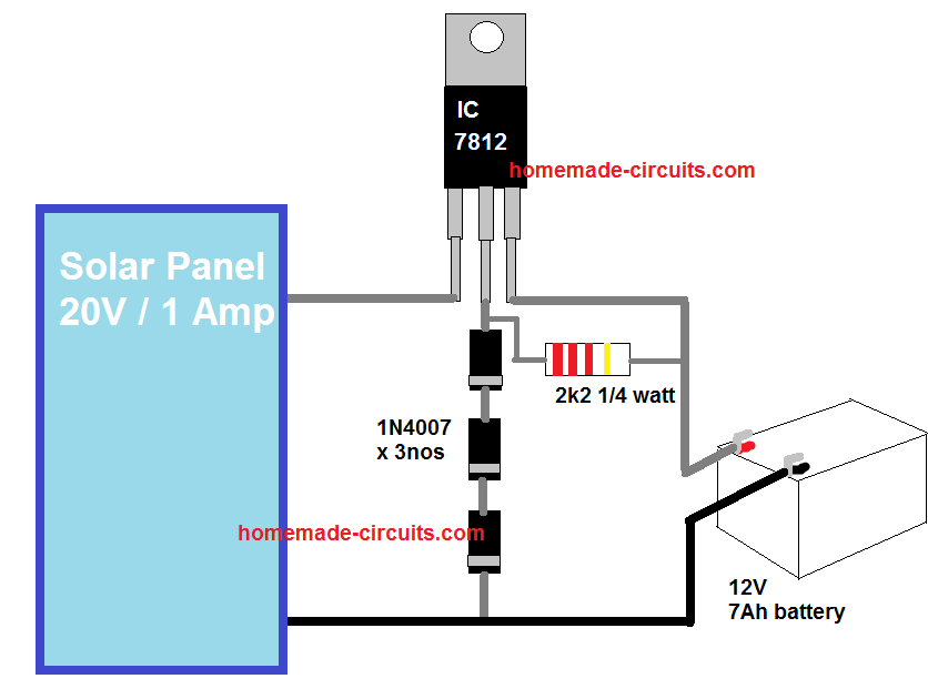
As we know the IC 7812 will produce a fixed 12V at the output which cannot be used for charging a 12V battery. The 3 diodes connected at its ground (GND) terminals is introduced specifically to counter this problem, and to upgrade the IC output to about 12 + 0.7 + 0.7 + 0.7 V = 14.1 V, which is exactly what is required for charging a 12 V battery fully.
The drop of 0.7 V across each diodes raises the grounding threshold of the IC by stipulated level forcing the IC to regulate the output at 14.1 V instead of 12 V. The 2k2 resistor is used to activate or bias the diodes so that it can conduct and enforce the intended 2.1 V total drop.
Making it Even Simpler
If you are looking for an even simpler solar charger, then probably there cannot be anything more straightforward than connecting an appropriately rated solar panel directly with the matching battery via a blocking diode, as shown below:
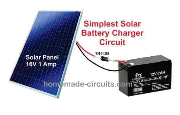
Although, the above design does not incorporate a regulator, it will still work since the panel current output is nominal, and this value will only show a deterioration as the sun changes its position.
However, for a battery that is not fully discharged, the above simple set up may cause some harm to the battery, since the battery will tend to get charged quickly, and will continue to get charged to unsafe levels and for longer periods of time.
You may also like this Highly Efficient 0-50V Solar Charger Circuit
1) Using LM338 as Solar Controller
But thanks to the modern highly versatile chips like the LM 338 and LM 317, which can handle the above situations very effectively, making the charging process of all rechargeable batteries through a solar panel very safe and desirable.
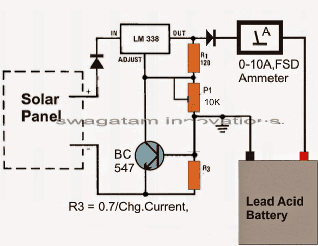
The circuit of a simple LM338 solar battery charger is shown below, using the IC LM338:
Parts List (BOM)
- Resistors
- R1 = 240 ohms 1/4 watt 5% CFR
- R3 = 0.6/Max Battery Charging Current
- P1 = 10k preset
- Diodes are 6A4
- Transistor = BC547
- IC = LM338
- Solar Panel = 18V, 5 Amp
- Battery =12V, 30 to 50 Ah
The circuit diagram shows a simple set up using the IC LM 338 which has been configured in its standard regulated power supply mode.
Using a Current Control Feature
The specialty of the design is that it incorporates a current control feature also.
It means that, if the current tends to increase at the input, which might normally take place when the sun ray intensity increases proportionately, the voltage of the charger drops proportionately, pulling down the current back to the specified rating.
As we can see in the diagram, the collector/emitter of the transistor BC547 is connected across the ADJ and the ground, it becomes responsible for initiating the current control actions.
As the input current rises, the battery starts drawing more current, this build up a voltage across R3 which is translated into a corresponding base drive for the transistor.
The transistor conducts and corrects the voltage via the C LM338, so that the current rate gets adjusted as per the safe requirements of the battery.
Current Limit Formula:
R3 may be calculated with the following formula
R3 = 0.7/ Max Current Limit
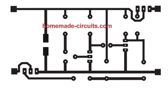
PCB Design for the above explained simple solar battery charger circuit is given below:
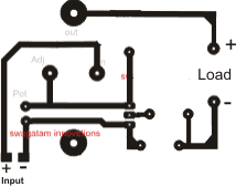
The meter and the input diode are not included in the PCB.
2) $1 Solar Battery Charger Circuit
The second design explains a cheap yet effective, less than $1 cheap yet effective solar charger circuit, which can be built even by a layman for harnessing efficient solar battery charging.
You will need just a solar panel panel, a selector switch and some diodes for getting a reasonably effective solar charger set up.
What is Maximum Power Point Solar Tracking?
For a layman this would be something too complex and sophisticated to grasp and a system involving extreme electronics.
In a way it may be true and surely MPPTs are sophisticated high end devices which are meant for optimizing the charging of the battery without altering the solar panel V/I curve.
In simple words an MPPT tracks the instantaneous maximum available voltage from the solar panel and adjusts the charging rate of the battery such that the panel voltage remains unaffected or away from loading.
Put simply, a solar panel would work most efficiently if its maximum instantaneous voltage is not dragged down close to the connected battery voltage, which is being charged.
For example, if the open circuit voltage of your solar panel is 20V and the battery to be charged is rated at 12V, and if you connect the two directly would cause the panel voltage to drop to the battery voltage, which would make things too inefficient.
Conversely if you could keep the panel voltage unaltered yet extract the best possible charging option from it, would make the system work with MPPT principle.
So it's all about charging the battery optimally without affecting or dropping the panel voltage.
There's one simple and zero cost method of implementing the above conditions.
Choose a solar panel whose open circuit voltage matches the battery charging voltage. Meaning for a 12V battery you may choose a panel with 15V and that would produce maximum optimization of both the parameters.
However practically the above conditions could be difficult to achieve because solar panels never produce constant outputs, and tend to generate deteriorating power levels in response to varying sun ray positions.
That's why always a much higher rated solar panel is recommended so that even under worse day time conditions it keeps the battery charging.
Having said that, by no means it is necessary to go for expensive MPPT systems, you can get similar results by spending a few bucks for it. The following discussion will make the procedures clear.
How the Circuit Works
As discussed above, in order to avoid unnecessary loading of the panel we need to have conditions ideally matching the PV voltage with the battery voltage.
This can be done by using a few diodes, a cheap voltmeter or your existing multimeter and a rotary switch. Ofcourse at around $1 you cannot expect it to be automatic, you may have to work with the switch quite a few times each day.
We know that a rectifier diode's forward voltage drop is around 0.6 volts, so by adding many diodes in series it can be possible to isolate the panel from getting dragged to the connected battery voltage.
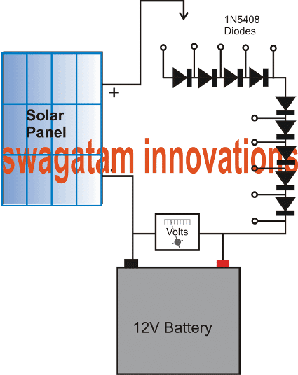
Referring to the circuit digaram given below, a cool little MPPT charger can be arranged using the shown cheap components.
Let's assume in the diagram, the panel open circuit voltage to be 20V and the battery to be rated at 12V.
Connecting them directly would drag the panel voltage to the battery level making things inappropriate.
By adding 9 diodes in series we effectively isolate the panel from getting loaded and dragged to the battery voltage and yet extract the Maximum charging current from it.
The total forward drop of the combined diodes would be around 5V, plus battery charging voltage 14.4V gives around 20V, meaning once connected with all the diodes in series during peak sunshine, the panel voltage would drop marginally to may be around 19V resulting an efficient charging of the battery.
Now suppose the sun begins dipping, causing the panel voltage to drop below the rated voltage, this can be monitored across the connected voltmeter, and a few diodes skipped until the battery is restored with receiving optimal power.
The arrow symbol shown connected with the panel voltage positive can be replaced with a rotary switched for the recommended selection of the diodes in series.
With the above situation implemented, a clear MPPT charging conditions can be simulated effectively without employing costly devices. You can do this for all types of panels and batteries just by including more number of diodes in series.
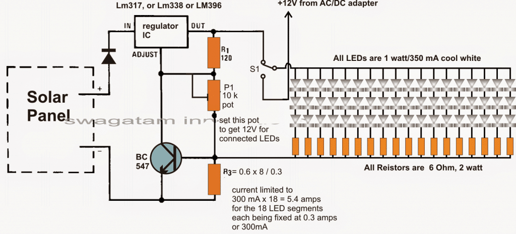
3) Solar Charger and Driver Circuit for 10W/20W/30W/50W White High Power SMD LED
The 3rd idea teaches us how to build a simple solar LED with battery charger circuit for illuminating high power LED (SMD) lights in the order of 10 watt to 50 watt. The SMD LEDs are fully safeguarded thermally and from over current using an inexpensive LM 338 current limiter stage. The idea was requested by Mr. Sarfraz Ahmad.
Technical Specifications
Basically I am a certified mechanical engineer from Germany 35 years ago and worked overseas for many years and left many years ago due to personal problems back home.
Sorry to bother you but I know about your capabilities and expertise in electronics and sincerity to help and guide the beginnings like me.I have seen this circuit some where for 12 vdc.I have attached to SMD ,12v 10 watt, cap 1000uf,16 volt and a bridge rectifier you can see the part number on that.When I turn the lights on the rectifier starts to heat up and the both SMDs as well. I am afraid if these lights are left on for a long time it may damage the SMDs and rectifier. I don not know where the problem is. You may help me.
I have a light in car porch which turns on at disk and off at dawn. Unfortunately due to load shedding when there is no electricity this light remains off till the electricity is back.
I want to install at least two SMD (12 volt) with LDR so as soon the light turns off the SMD lights will turn on. I want to additional two similar light elsewhere in the car porch to keep the entire are lighted.I think that if I connect all these four SMD lights with 12 volt power supply which will get the power from UPS circuit.
Of course it will put additional load on UPS battery which is hardly fully charged due to frequent load shedding. The other best solution is to install 12 volt solar panel and attach all these four SMD lights with it. It will charge the battery and will turn the lights On/OFF.
This solar panel should be capable to keeps these lights all the night and will turn OFF at dawn.Please also help me and give details about this circuit/project.
You may take your time to figure out how to do that.I am writing to you as unfortunately no electronics or solar product seller in our local market is willing to give me any help, None of them seems to be technical qualified and they just want to sell their parts.
Sarfraz AhmadRawalpindi, Pakistan
Highly Recommended for you: Solar Chargers using Switching Regulators
The Design
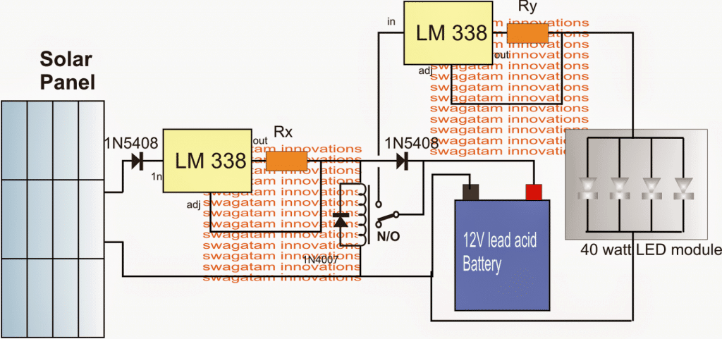
In the shown 10 watt to 50 watt SMD solar LED light circuit with automatic charger above, we see the following stages:
- A solar panel
- A couple of current controlled LM338 regulator circuits
- A changeover relay
- A rechargeable battery
- and a 40 watt LED SMD module
The above stages are integrated in the following explained manner:
The two LM 338 stages are configured in standard current regulator modes with using the respective current sensing resistances for ensuring a current controlled output for the relevant connected load.
The load for the left LM338 is the battery which is charged from this LM338 stage and a solar panel input source. The resistor Rx is calculated such that the battery receives the stipulated amount of current and is not over driven or over charged.
The right side LM 338 is loaded with the LED module and here too the Ry makes sure that module is supplied with the correct specified amount of current in order to safeguard the devices from a thermal runaway situation.
The solar panel voltage specs may be anywhere between 18V and 24V.
A relay is introduced in the circuit and is wired with the LED module such that it's switched ON only during the night or when it's dark below threshold for the solar panel to generate the required any power.
As long as the solar voltage is available, the relay stays energized isolating the LED module from the battery and ensuring that the 40 watt LED module remains shut off during day time and while the battery is being charged.
After dusk, when the solar voltage becomes sufficiently low, the relay is no longer able to hold its N/O position and flips to the N/C changeover, connecting the battery with the LED module, and illuminating the array through the available fully charged battery power.
The LED module can be seen attached with a heatsink which must be sufficiently large in order to achieve an optimal outcome from the module and for ensuring longer life and brightness from the device.
Calculating the Resistor Values
The indicated limiting resistors may be calculated from the given formulas:
Rx = 1.25/battery charging current
Ry = 1.25/LED current rating.
Assuming the battery to be a 40 AH lead acid battery, the preferred charging current should be 4 amps.
therefore Rx = 1.25/4 = 0.31 ohms
wattage = 1.25 x 4 = 5 watts
The LED current can be found by dividing its total wattage by the voltage rating, that is 40/12 = 3.3amps
therefore Ry = 1.25/3 = 0.4 ohms
wattage = 1.25 x 3 = 3.75 watts or 4 watts.
Limiting resistors are not employed for the 10 watt LEDs since the input voltage from the battery is on par with the specified 12V limit of the LED module and therefore cannot exceed the safe limits.
The above explanation reveals how the IC LM338 can be simply used for making an useful solar LED light circuit with an automatic charger.
4) Automatic Solar Light Circuit using a Relay
In our 4rth automatic solar light circuit we incorporate a single relay as a switch for charging a battery during day time or as long as the solar panel is generating electricity, and for illuminating a connected LED while the panel is not active.
Upgrading to a Relay Changeover
In one of my previous article which explained a simple solar garden light circuit, we employed a single transistor for the switching operation.
One disadvantage of the earlier circuit is, it does not provide a regulated charging for the battery, although it not might be strictly essential since the battery is never charged to its full potential, this aspect might require an improvement.
Another associated disadvantage of the earlier circuit is its low power spec which restricts it from using high power batteries and LEDs.
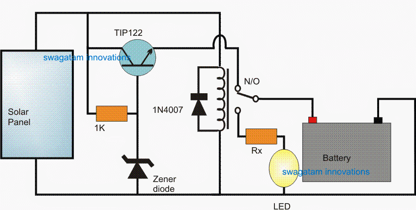
The following circuit effectively solves both the above two issues, with the help of a relay and a emitter follower transistor stage.
Circuit Diagram
How it Works
During optimal sun shine, the relay gets sufficient power from the panel and remains switched ON with its N/O contacts activated.
This enables the battery to get the charging voltage through a transistor emitter follower voltage regulator.
The emitter follower design is configured using a TIP122, a resistor and a zener diode. The resistor provides the necessary biasing for the transistor to conduct, while the zener diode value clamps the emitter voltage is controlled at just below the zener voltage value.
The zener value is therefore appropriately chosen to match the charging voltage of the connected battery.
For a 6V battery the zener voltage could be selected as 7.5V, for 12V battery the zener voltage could be around 15V and so on.
The emitter follower also makes sure that the battery is never allowed to get overcharged above the allocated charging limit.
During evening, when a substantial drop in sunlight is detected, the relay is inhibited from the required minimum holding voltage, causing it to shift from its N/O to N/C contact.
The above relay changeover instantly reverts the battery from charging mode to the LED mode, illuminating the LED through the battery voltage.
Parts list for a 6V/4AH automatic solar light circuit using a relay changeover
- Solar Panel = 9V, 1amp
- Relay = 6V/200mA
- Rx = 10 ohm/2 watt
- zener diode = 7.5V, 1/2 watt
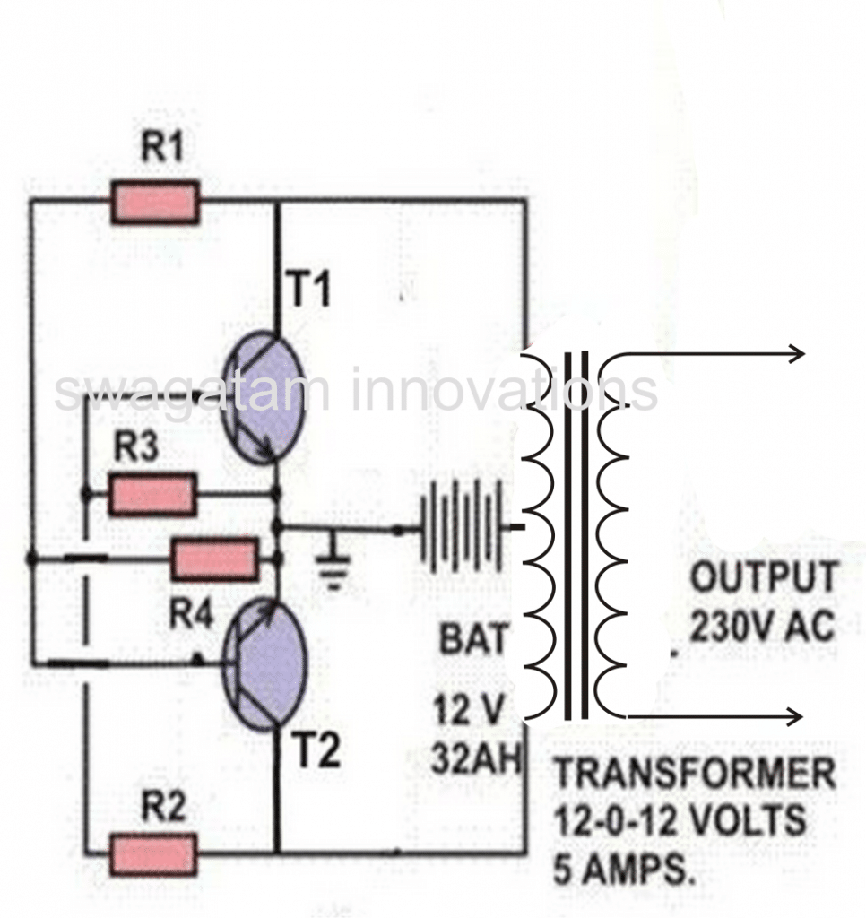
5) Transistorized Solar Charger Controller Circuit
The fifth idea presented below details a simple solar charger circuit with automatic cut-off using transistors only. The idea was requested by Mr. Mubarak Idris.
Circuit Objectives and Requirements
- Please sir can you make me a 12v, 28.8AH lithium ion battery,automatic charge controller using solar panel as a supply, which is 17v at 4.5A at max sun light.
- The charge controller should be able to have over charge protection and low battery cut off and the circuit should be simple to do for beginner without ic or micro controller.
- The circuit should use relay or bjt transistors as a switch and zener for voltage reference thanks sir hope to hear from you soon!
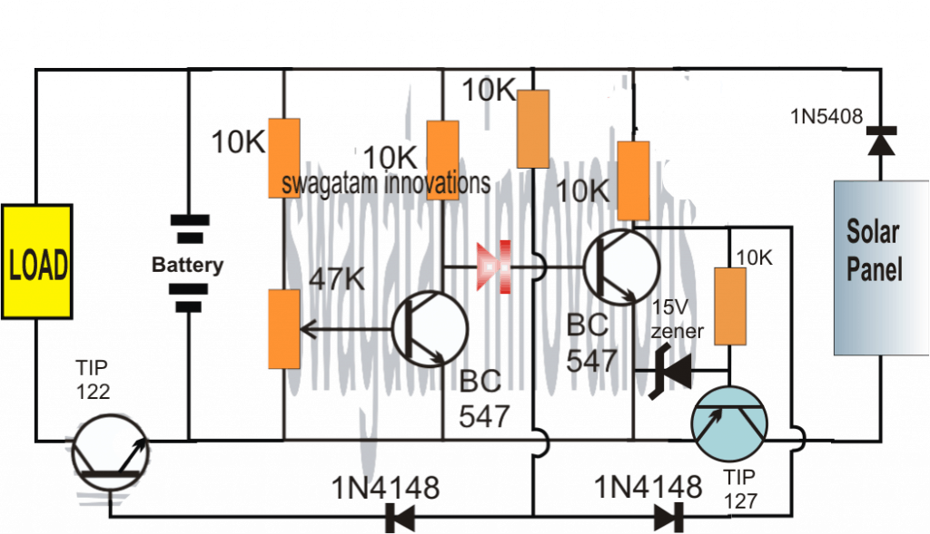
The Design
PCB Design (Component Side)
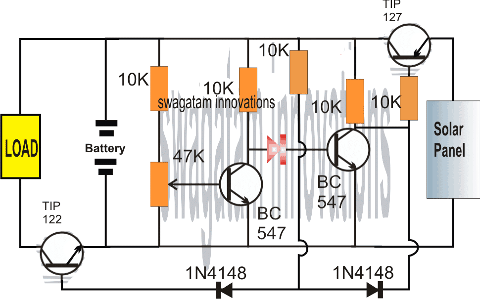
Referring to the above simple solar charger circuit using transistors, the automatic cut off for the full charge charge level and the lower level is done through a couple of BJTs configured as comparators.
Recall the earlier low battery indicator circuit using transistors, where the low battery level was indicated using just two transistors and a few other passive components.
Here we employ an identical design for the sensing of the battery levels and for enforcing the required switching of the battery across the solar panel and the connected load.
Let's assume initially we have a partially discharged battery which causes the first BC547 from left to stop conducting (this is set by adjusting the base preset to this threshold limit), and allows the next BC547 to conduct.
When this BC547 conducts it enable the TIP127 to switch ON, which in turn allows the solar panel voltage to reach the battery and begin charging it.
The above situation conversely keeps the TIP122 switched OFF so that the load is unable to operate.
As the battery begins getting charged, the voltage across the supply rails also begin rising until a point where the left side BC547 is just able to conduct, causing the right side BC547 to stop conducting any further.
As soon as this happens, the TIP127 is inhibited from the negative base signals and it gradually stops conducting such that the battery gradually gets cut off from the solar panel voltage.
However, the above situation permits the TIP122 to slowly receive a base biasing trigger and it begins conducting....which ensures that the load now is able to get the required supply for its operations.
The above explained solar charger circuit using transistors and with auto cut-offs can be used for any small scale solar controller applications such as for charging cellphone batteries or other forms of Li-ion batteries safely.
For getting a Regulated Charging Supply
The following design shows how to convert or upgrade the above circuit diagram into a regulated charger, so that the battery is supplied with a fixed and a stabilized output regardless of a rising voltage from the solar panel.
The above designs can be further simplified, as shown in the following over-charge, over-discharge solar battery controller circuit:
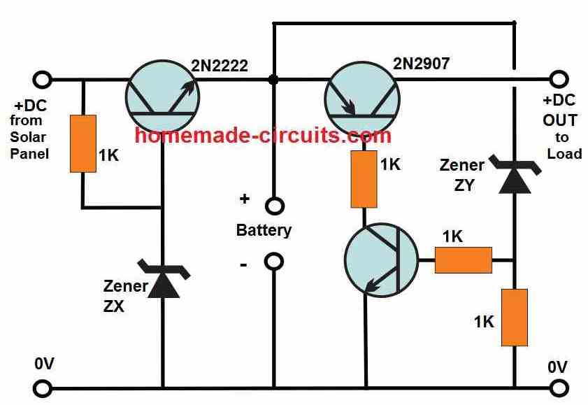
Here, the zener ZX decides the full charge battery cut off, and can be calculated using the following formula:
ZX = Battery full charge value + 0.6
For example, if the full-charge battery level is 14.2V, then the ZX can be 14 + 0.6 = 14.6V zener which can be built by adding a few zener diodes in series, along with a few 1N4148 diodes, if required.
The zener diode ZY decides the battery over-discharge cut off point, and can be simply equal to the value of the desired low battery value.
For example if the minimum low battery level is 11V, then the ZY can be selected to be a 11V zener.
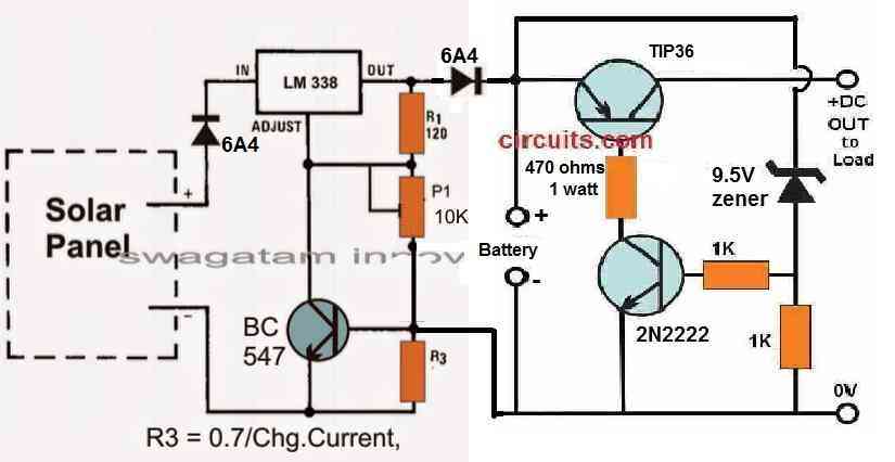
The above design can be also integrated with an LM338 charger circuit as shown below:
6) Solar Pocket LED Light Circuit
The sixth design here explains a simple low cost solar pocket LED light circuit which could be used by the needy and, underprivileged section of the society for illuminating their houses at night cheaply.
The idea was requested by Mr. R.K. Rao
Circuit Objectives and Requirements
- I want to make a SOLAR pocket LED light using a 9cm x 5cm x 3cm transparent plastic box [available in the market for Rs.3/-] using a one watt LED/20mA LEDS powered by a 4v 1A rechargeable sealed lead-acid battery [SUNCA/VICTARI] & also with a provision for charging with a cell phone charger [where grid current is available].
- The battery should be replaceable when dead after use for 2/3 years/prescribed life by the rural/tribal user.
- This is meant for use by tribal/rural children to light up a book; there are better led lights in the market for around Rs.500 [d.light],for Rs.200 [Thrive].
- These lights are good except that they have a mini solar panel and a bright LED with a life of ten years if not more ,but with a rechargeable battery without a provision for its replacement when dead after two or three years of use.It is a waste of resource and unethical.
- The project i am envisaging is one in which the battery can be replaced , be locally available at low cost. The price of the light should not exceed Rs.100/150.
- It will be marketed on not for profit basis through NGOs in tribal areas and ultimately supply kits to tribal/rural youth to make them in the village.
- I along with a colleague have made some lights with 7V EW high power batteries and 2x20mA pirahna Leds and tested them-they lasted for over 30 hours of continuous lighting adequate to light up a book from half-meter distance; and another with a 4v sunce battery and 1watt 350A LED giving enough light for cooking in a hut.
- Can you suggest a circuit with a one AA/AAA rechargeable battery,mini solar panel to fit on the box cover of 9x5cm and a DC-DC booster and 20mA leds. If you want me to come over to your place for discussions i can.
- You can see the lights we have made in google photos at https://goo.gl/photos/QyYU1v5Kaag8T1WWA Thanking you,
The Design
As per the request the solar pocket LED light circuits needs to be compact, work with a single 1.5AAA cell using a DC-DC converter and equipped with a self regulating solar charger circuit.
The circuit diagram shown below probably satisfies all the above specifications and yet stays within the affordable limit.
Circuit Diagram

The design is a basic joule thief circuit using a single penlight cell, a BJT and an inductor for powering any standard 3.3V LED.
In the design a 1 watt LeD is shown although a smaller 30mA high bright LED could be used.
The solar LED circuit is capable squeezing out the last drop of "joule" or the charge from the cell and hence the name joule thief, which also implies that the LED would keep illuminated until there's virtually nothing left inside the cell. However the cell here being a rechargeable type is not recommended to be discharged below 1V.
The 1.5V battery charger in the design is built using another low power BJT configured in its emitter follower configuration, which allows it to produce an emitter voltage output that's exactly equal to the potential at its base, set by the 1K preset. This must be precisely set such that the emitter produces not more than 1.8V with a DC input of above 3V.
The DC input source is a solar panel which may be capable of producing an excess of 3V during optimal sunlight, and allow the charger to charge the battery with a maximum of 1.8V output.
Once this level is reached the emitter follower simply inhibits any further charging of the cell thus preventing any possibility of an over charge.
The inductor for the pocket solar LED light circuit consists of a small ferrite ring transformer having 20:20 turns which could be appropriately altered and optimized for enabling the most favorable voltage for the connected LED which may last even until the voltage has fallen below 1.2V.
7) Simple Solar Charger for Street Lights
The seventh solar charger discussed here is best suited as a solar LED street light system is specifically designed for the new hobbyist who can build it simply by referring to the pictorial schematic presented here.
Due to its straightforward and relatively cheaper design the system can be suitably used for village street lighting or in other similar remote areas, nonetheless this by no means restricts it from being used in cities also.
Main Features of this system are:
1) Voltage controlled Charging
2) Current Controlled LED Operation
3) No Relays used, all Solid-State Design
4) Low Critical Voltage Load Cut-off
5) Low Voltage and Critical Voltage Indicators
6) Full Charge cut-off is not included for simplicity sake and because the charging is restricted to a controlled level which will never allow the battery to over-charge.
7) Use of popular ICs like LM338 and transistors like BC547 ensure hassle free procurement
8) Day night sensing stage ensuring automatic switch OFF at dusk and switch ON at dawn.
The entire circuit design of the proposed simple LED street light system is illustrated below:
Circuit Diagram
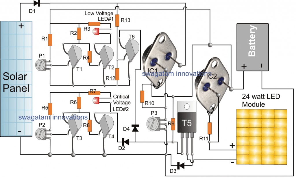
The circuit stage comprising T1, T2, and P1 are configured into a simple low battery sensor, indicator circuit
An exactly identical stage can also be seen just below, using T3, T4 and the associated parts, which form another low voltage detector stage.
The T1, T2 stage detects the battery voltage when it drops to 13V by illuminating the attached LED at the collector of T2, while the T3, T4 stage detects the battery voltage when it reaches below 11V, and indicates the situation by illuminating the LED associated with the collector of T4.
P1 is used for adjusting the T1/T2 stage such that the T2 LED just illuminates at 12V, similarly P2 is adjusted to make the T4 LED begin illuminating at voltages below 11V.
IC1 LM338 is configured as a simple regulated voltage power supply for regulating the solar panel voltage to a precise 14V, this is done by adjusting the preset P3 appropriately.
This output from IC1 is used for charging the street lamp battery during day time and peak sunshine.
IC2 is another LM338 IC, wired in a current controller mode, its input pin is connected with the battery positive while the output is connected with the LED module.
IC2 restricts the current level from the battery and supplies the right amount of current to the LED module so that it is able operate safely during night time back up mode.
T5 is a power transistor which acts like a switch and is triggered by the critical low battery stage, whenever the battery voltage tends to reach the critical level.
Whenever this happens the base of T5 is instantly grounded by T4, shutting it off instantly. With T5 shut off, the LED module is enable to illuminate and therefore it is also shut off.
This condition prevents and safeguards the battery from getting overly discharged and damaged. In such situations the battery might need an external charging from mains using a 24V, power supply applied across the solar panel supply lines, across the cathode of D1 and ground.
The current from this supply could be specified at around 20% of battery AH, and the battery may be charged until both the LEDs stop glowing.
The T6 transistor along with its base resistors is positioned to detect the supply from the solar panel and ensure that the LED module remains disabled as long as a reasonable amount of supply is available from the panel, or in other words T6 keeps the LED module shut off until its dark enough for the LED module and then is switched ON. The opposite happen at dawn when the LED module is automatically switched OFF. R12, R13 should be carefully adjusted or selected to determine the desired thresholds for the LED module's ON/OFF cycles
How to Build
To complete this simple street light system successfully, the explained stages must be built separately and verified separately before integrating them together.
First assemble the T1, T2 stage along with R1, R2, R3, R4, P1 and the LED.
Next, using a variable power supply, apply a precise 13V to this T1, T2 stage, and adjust P1 such that the LED just illuminates, increase the supply a bit to say 13.5V and the LED should shut off. This test will confirm the correct working of this low voltage indicator stage.
Identically make the T3/T4 stage and set P2 in a similar fashion to enable the LED to glow at 11V which becomes the critical level setting for the stage.
After this you can go ahead with the IC1 stage, and adjust the voltage across its "body" and ground to 14V by adjusting P3 to the correct extent. This should be again done by feeding a 20V or 24V supply across its input pin and ground line.
The IC2 stage can be built as shown and will not require any setting up procedure except the selection of R11 which may be done using the formula as expressed in this universal current limiter article
Parts List
- R1, R2, R3 R4, R5, R6, R7 R8, R9, R12 = 10k, 1/4 WATT
- P1, P2, P3 = 10K PRESETS
- R10 = 240 OHMS 1/4 WATT
- R13 = 22K
- D1, D3 = 6A4 DIODE
- D2, D4 = 1N4007
- T1, T2, T3, T4 = BC547
- T5 = TIP142
- R11 = SEE TEXT
- IC1, IC2 = LM338 IC TO3 package
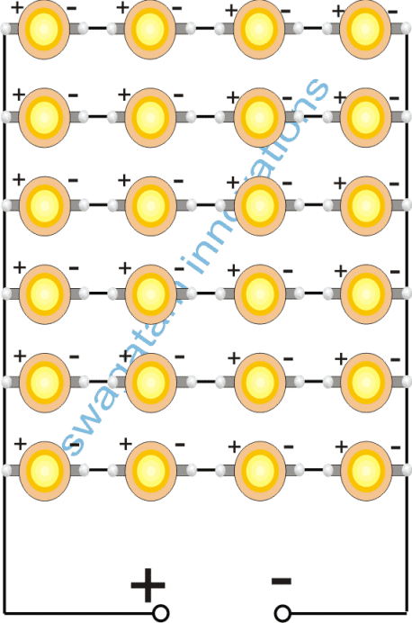
- LED Module = Made by connecting 24nos 1 WATT LEDs in series and parallel connections
- Battery = 12V SMF, 40 AH
- Solar Panel = 20/24V, 7 Amp
Making th 24 watt LED Module
The 24 watt LED module for the above simple solar street light system could be built simply by joining 24 nos 1 watt LEDs as shown in the following image:
8) Solar Panel Buck Converter Circuit with Over Load Protection
The 8th solar concept discussed below talks about a simple solar panel buck converter circuit which can be used to obtain any desired low bucked voltage from 40 to 60V inputs. The circuit ensures a very efficient voltage conversions. The idea was requested by Mr. Deepak.
Technical Specifications
I am looking for DC - DC buck converter with following features.
1. Input voltage = 40 to 60 VDC
2. Output voltage = Regulated 12, 18 and 24 VDC (multiple output from the same circuit is not required. Separate circuit for each o/p voltage is also fine)
3. Output current capacity = 5-10A
4. Protection at output = Over current, short circuits etc.
5. Small LED indicator for unit operation would be an advantage.
Appreciate if you could help me designing the circuit.
Best regards,
Deepak
The Design
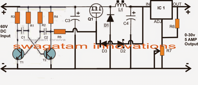
The proposed 60V to 12V, 24V buck converter circuit is shown in the figure below, the details may be understood as I have explained below:
The configuration could be divided into stages, viz. the astable multivibrator stage and the mosfet controlled buck converter stage.
BJT T1, T2 along with its associated parts forms a standard AMV circuit wired to generate a frequency at the rate of about 20 to 50kHz.
Mosfet Q1 along with L1 and D1 forms a standard buck converter topology for implementing the required buck voltage across C4.
The AMV is operated by the input 40V and the generated frequency is fed to the gate of the attached mosfet which instantly begins oscillating at the available current from the input driving L1, D1 network.
The above action generates the required bucked voltage across C4,
D2 makes sure that this voltage never exceeds the rated mark which may be fixed 30V.
This 30V max limit bucked voltage is further fed to a LM396 voltage regulator which may be set for getting the final desired voltage at the output at the rate of 10amps maximum.
The output may be used for charging the intended battery.
Circuit Diagram
Parts List for the above 60V input, 12V, 24V output buck converter solar for the panels.
- R1---R5 = 10K
- R6 = 240 OHMS
- R7 = 10K POT
- C1, C2 = 2nF
- C3 = 100uF/100V
- C4 = 100uF/50V
- Q1 = ANY 100V, 20AMP P-channel MOSFET
- T1,T2 = BC546
- D1 = ANY 10AMP FAST RECOVERY DIODE
- D2 = 30V ZENER 1 WATT
- D3 = 1N4007
- L1 = 30 turns of 21 SWG super enameled copper wire wound over a 10mm dia ferrite rod.
9) Home Solar Electricity Set up for an Off-the-grid Living
The ninth unique design explained here illustrates a simple calculated configuration which may be used for implementing any desired sized solar panel electricity set up for remotely located houses or for achieving an off the grid electricity system from solar panels.
Technical Specifications
I am very sure you must have this kind of circuit diagram ready. While going through your blog I got lost and could not really choose one best fitting to my requirements.
I am just trying to put my requirement here and make sure I understood it correctly.
(This is a pilot project for me to venture into this field. You can count me to be a big zero in electrical knowledge. )
My basic goal is to maximize use of Solar power and reduce my electrical bill to minimum. ( 🙁 I stay at Thane. So, you can imagine electricity bills. ) So you can consider as if I am completely making a solar powered lighting system for my home.
1. Whenever there is enough sunlight, I do not need any artificial light.2. Whenever intensity of sunlight drops below acceptable norms, I wish my lights will turn on automatically.
I would like to switch them off during bedtime, though.3. My current lighting system (which I wish to illuminate) consists of two regular bright light Tube lights ( 36W/880 8000K ) and four 8W CFLs.
Would like to replicate the whole setup with Solar-powered LED based lighting.
As I said, I am a big zero in field of electricity. So, please help me with the expected setup cost also.
The Design
36 watts x 2 plus 8 watt gives a total of around 80 watts which is the total required consumption level here.
Now since the lights are specified to work at mains voltage levels which is 220 V in India, an inverter becomes necessary for converting the solar panel voltage to the required specs for the lights to illuminate.
Also since the inverter needs a battery to operate which can be assumed to be a 12 V battery, all the parameters essential for the set up may be calculated in the following manner:
Total intended consumption is = 80 watts.
The above power may be consumed from 6 am to 6 pm which becomes the maximum period one can estimate, and that's approximately 12 hours.
Multiplying 80 by 12 gives = 960 watt hour.
It implies that the solar panel will need to produce this much watt hour for the desired period of 12 hours during the entire day.
However since we don't expect to receive optimum sunlight through the year, we can assume the average period of optimum daylight to be around 8 hours.
Dividing 960 by 8 gives = 120 watts, meaning the required solar panel will need to be at least 120 watt rated.
If the panel voltage is selected to be around 18 V, the current specs would be 120/18 = 6.66 amps or simply 7 amps.
Now let's calculate the battery size which may be employed for the inverter and which may be required to be charged with the above solar panel.
Again since the total watt hour fr the entire day is calculated to be around 960 watts, dividing this with the battery voltage (which is assumed to be 12 V) we get 960/12 = 80, that's around 80 or simply 100 AH, therefore the required battery needs to be rated at 12 V, 100 AH for getting an an optimal performance throughout the day (12 hours period).
We'll also need a solar charge controller for charging the battery, and since the battery would be charged for the period of around 8 hours, the charging rate will need to be around 8% of the rated AH, that amounts to 80 x 8% = 6.4 amps, therefore the charge controller will need to be specified to handle at least 7 amp comfortably for the required safe charging of the battery.
That concludes the entire solar panel, battery, inverter calculations which could be successfully implemented for any similar kind of set up intended for an off the grid living purpose in rural areas or other remote area.
For other V, I specs, the figures may be changed in the above explained calculation for achieving the appropriate results.
In case the battery is felt unnecessary and the solar panel could also be directly used for operating inverter.
A simple solar panel voltage regulator circuit may be witnessed in the following diagram, the given switch may be used for selecting a battery charging option or directly driving the inverter through the panel.
In the above case, the regulator needs to produce around 7 to 10amps of current therefore an LM396 or LM196 must be used in the charger stage.
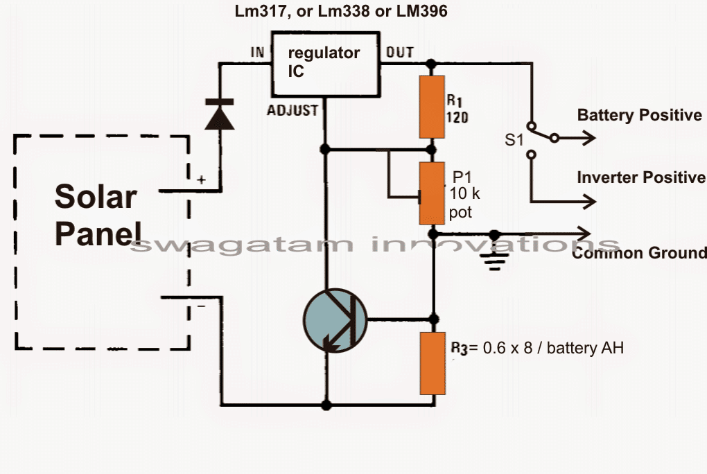
The above solar panel regulator may be configured with the following simple inverter circuit which will be quite adequate for powering the requested lamps through the connected solar panel or the battery.
Parts list for the above inverter circuit: R1, R2 = 100 ohm, 10 watt
R3, R4 = 15 ohm 10 watt
T1, T2 = TIP35 on heatsinks
The last line in the request suggests an LED version to be designed for replacing and upgrading the existing CFL fluorescent lamps. The same may be implemented by simply eliminating the battery and the inverter and integrating the LEDs with the solar regulator output, as shown below:
The negative of the adapter must be connected and made common with the negative of the solar panel
Final Thoughts
So friends these were 9 basic solar battery charger designs, which were hand picked from this website.
You will find many more such enhanced solar based designs in the blog for further reading. And yes, if you have any additional idea you may definitely submit it to me, I'll make sure to introduce it here for the reading pleasure of our viewers.
Feedback from one of the Avid Readers
Hi Swagatam,
I have come across your site and find your work very inspiring. I am currently working on a Science, Technology, Engineering and Math (STEM) program for year 4-5 students in Australia. The project focuses on increasing children’s curiosity about science and how it connects to real-world applications.
The program also introduces empathy in the engineering design process where young learners are introduced to a real project (context) and engages with their fellow school peers to solve a worldly problem. For the next three years, our focus is on introducing children to the science behind electricity and the real-world application of electrical engineering. An introduction to how engineers solve real-world problems for the greater good of society.
I am currently working on online content for the program, which will focus on young learners(Grade 4-6) learning the basics of electricity, in particular, renewable energy, i.e. solar in this instance. Through a self-directed learning program, children learn and explore about electricity and energy, as they are introduced to a real-world project, i.e. providing lighting to children sheltered in the refugee camps around the world. On completion of a five-week program, children are grouped in teams to construct solar lights, which are then sent to the disadvantaged children around the world.
As a not 4 profit educational foundation we are seeking your assistance to layout a simple circuit diagram, which could be used for the construction of a 1 watt solar light as practical activity in class. We have also procured 800 solar light kits from a manufacturer, which the children will assemble, however, we need someone to simplify the circuit diagram of these light kits, which will be used for simple lessons on electricity, circuits, and calculation of power, volts, current and conversion of solar energy to electrical energy.
I look forward to hearing from you and keep on with your inspiring work.
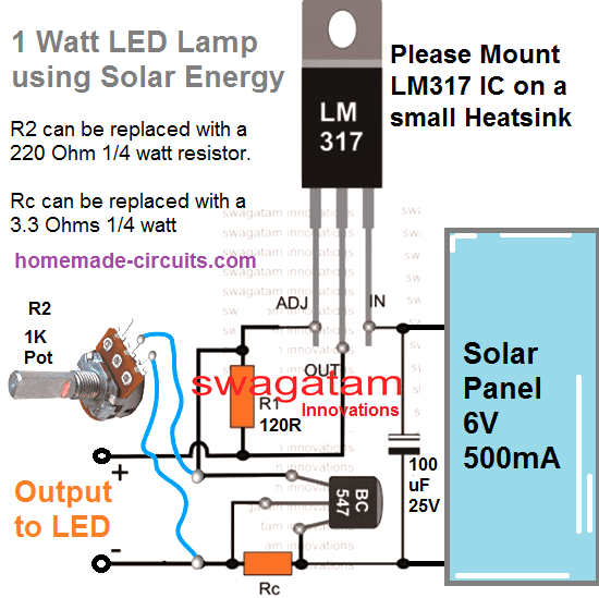
Solving the Request
I appreciate your interest and your sincerely efforts to enlighten the new generation regarding solar energy.
I have attached the most simple yet efficient LED driver circuit which can be used for illuminating a 1 watt LED from a solar panel safely with minimum parts.
Make sure to attach a heatsink on the LED, otherwise it may burn quickly due to overheating.
The circuit is voltage controlled and current controlled for ensuring optimum safety to the LED.
Let me know if you have any further doubts.
Request from one of the avid readers of this blog:
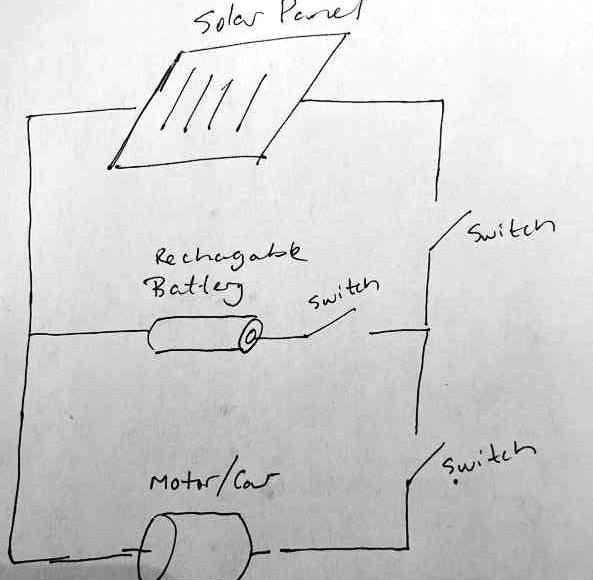
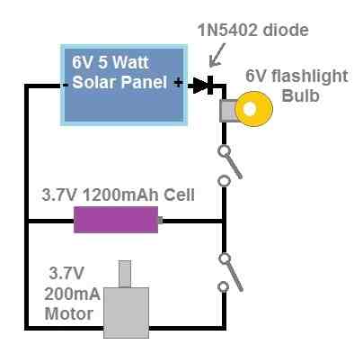
Hi, thank you for everything you do to help people out! My son would like to create a science fair experiment where he can show an electric car running on a solar panel only during the day while charging a battery and running on battery only during the night. For this, we planned to have a small solar panel connected to a battery and motor in parallel (see the attached drawing).
- Will this work?
- Can you recommend a size of solar panel, battery and motor?
- As to not overcharge the battery, should a resistor be added? What size would you recommend?
- Should a diode be added? What size would you recommend?
My Reply:
- yes, it will work.
- Use a 6 to 8V 1-amp solar panel.
- The switch in series with the battery is not required. The remaining two switches are fine. This switch can be replaced with a 4 ohm 2 watt, or simply a 6 V flashlight bulb.
- This bulb will illuminate while charging and will slowly shut off as the battery gets fully charged.
- You can add a diode in series with the positive wire of the solar panel. It can be a 1N5402 diode
- The battery can be any 3.7V 1200mAh Li-ion battery.
- Motor can be any 3.7V DC motor.
More Questions:
Couple more questions, I cannot find a solar panel with those specs, do you think you could send me one on the internet so I can find something similar? Great idea on the flashlight bulb, I assume this would need to be an incandescent light? Do you think this would properly protect the battery or would an additional resistor be needed?
My Reply:
For the solar panel, you can search for a 6V 5 watt solar panel.Yes, the flashlight bulb will need to be an incandescent type, so that the filament can be used to control the current.The bulb should be enough to control the current, no additional resistor will be required.Please find the attached diagram for the detailed schematic.
Sir
I also studied the transistor based circuit of 2n2222 will it work decently on 6 volt battery can I use Tip122 in place of 2n2222
please suggest something.
I want to become a designer like you , how it’s possible for me.
Good Evening Sir
Please suggest me the 6 volt 5 AH x 2 =10 ah battery to be charged with a 5 watts solar panel of around 11.1 volt.
The circuit shown by you with lm317 will dissipate more energy can you suggest me any transistor based circuit.
Good evening Dhananjay,
You will actually need a buck converter such as the following one, or any other similar:
https://www.homemade-circuits.com/ic-mp1584-datasheet-and-circuit-diagram/
https://www.homemade-circuits.com/adjustable-1-2v-to100v-dc-buck-converter-circuit-using-lm5164/
Then you an simply adjust the feedback resistor to fixx the precise charging voltage for your battery.
Thanks for speedy response, Sir
I am using a boost converter of xl6009/ cn6009 to increase my voltage to 7.2volt but the amp rating is declined very much. Will it charge a single 6 volt 4.5ah battery in a day.
Should I connect solar panel to battery through a diode , will it work.
Dhananjay, If your solar panel is 11V and you want to charge a 6V battery from it, then you will need a buck converter,, not a boost converter.
Since your solar panel is rated at 5 watts, that means it can generate a maximum of 5 / 11 = 450 mA currents, which is not sufficient for charging a 10Ah battery correctly.
So if you connect the battery directly with the solar panel then your battery will manage to get only 450 ma current max.
But if you use a buck converter, you might get a current boost of 90%, which will convert the 450mA to up to 750mA current, just enough for the battery.
please calculate for the 40ah battery using lm338
10% of 40 is 4.
so R = 0.6/4 = 0.15 ohms.
and power = 0.6 * 4 = 2.4 watts
thank you for correcting so the resistor is supposed to be 0.12 ohms
how about for sulphuric acid battery
You are welcome.
sulphuric acid battery is same as lead acid battery.
that means for resistor while using lm388 it’s for example 0.6 * 50ah = 30 ohms resistor
For lead acid battery the max charging current will be 10% of its Ah rating.
10% of 50 Ah is 5 ampere, so it will be 0.6/5 = 0.12 ohms, and 0.6 * 5 = 0.3 watts
By the way, you have written the formula and the IC number wrongly, please check carefully before writing.
what is the highest battery ah and the highest solar panel watts, please calculate for me the highest resistor we can put but remember you said the circuit can use lm371 or lm388 so for now I’m beginning with lm371
LM317 can provide a maximum of 1.5 amps, while LM338 can provide upto 5 amps.
For LM317 you can use 1.5 * 10 = 15 Ah battery maximum, and solar panel of 2 amp, 35V maximum
For LM338 you can use 5 * 10 = 50 Ah Battery maximum, and solar panel of 5 amp, and 35V maximum.
The batteries are lead acid batteries.
please let me understand what you meant by resistor you 0.6/battery please check the partlist of lm388 or lm317
Suppose the maximum charging current of your battery is 1 amp.
Then the current limiting resistor across the base/emitter of the transistor can be calculated using the formula:
R = 0.6/Charging current
= 0.6 / 1 = 0.6 ohms
Power of resistor will be 0.6 * 1 = 0.6 watts.
100w solar panel can charge how many ah battery? can we design a charge controller for it? please help
A 100W solar panel can charge approximately 23–28Ah of battery capacity per day, depending on the sun exposure and system efficiency.
you did not name the diodes used in the lm338 solar charge controller, and please write the ratings like for example minimum and maximum input and it’s output voltage rating (the solar panels that can be used and battery ah)
I have added the parts list just below the diagram, you can check it now…
Maximum solar panel voltage must not exceed 35V
Diodes are 6A4
it’s okay help design the solar charge controller for 70ah battery
You can try the following universal charger circuit: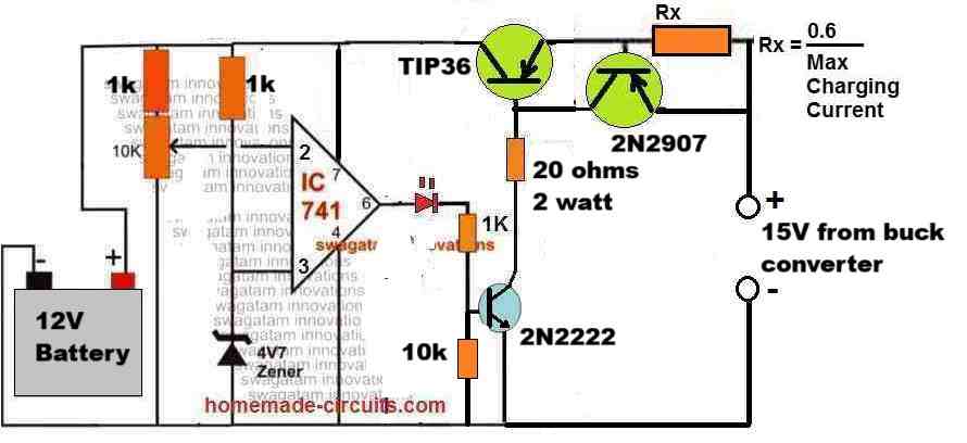
" rel="ugc">
battery 70ah 12v and solar panel 100w
is it possible to use 555 ic in making the charge controller
You will need a 24V 150 watt panel for charging a 70 Ah battery efficiently, a 100 watt panel might not charge optimally…
please help design 100w solar panel charge controller for 70ah battery
Please provide voltage ratings of the solar panel and battery….
1. from your second diagram using lm338 the diagram with a meter, can it also be used for charging 10w,20w,30w with 50w panel or it’s used for a specific type of panel only?
2. from your diagram or let me say your third diagram of 10w,20w,30w and 50w what if not everyone needs very many LED bulbs as you had drew, if it were to skip led bulbs what could we have replaced or what if it could be replaced with 3 or 4 indicator led bulbs?
Hello Rashid,
The LM338 can be used with 50 watt solar panel, provided the panel voltage is below 35V and the current is below 5 amps.
In the 3) design, you can reduce the number of LEDs, and accordingly adjust the current limiting value of the right side LM338 circuit.
Mr. Swagatam, thanks for the tips and information, I’m new with solar panels. I just got the task to design a battery charge for a multiple of solar panel ratings. we have 100w, 200w, 400 and 550 w panels that I need to see if we can design one charge that can accommodate all this panels. here is the situation the 100 w panel has an output of 12 to 19vdc when the 400 & 550 is 40 to 60vdc. I will need an indicator that the unit is on and charging, and a auto cut off when battery is full. output should be 12vdc
Thank you Ernesto,
You can try the following universal 12V battery charger circuit with auto cut off and over current protections with all your solar panels, for charging a 12V battery:
" rel="ugc">
However, you will need to add a buck converter for solar panels that are higher than 20V.
The preset associated with the 741 IC can be adjusted to implement the cut-off at around 14V.
Please let me know if you have any further doubts or questions…
Dear Mr. Swagatam, it is a pleasure to greet you and above all to enjoy your very varied designs that are useful for daily life.
My name is Guido Fernández Rosales and I am Cuban living in Havana.
Our country has a very delicate situation in relation to the national electricity system and its production of electrical energy and any solution that can be developed from Renewable Solar Photovoltaic energy to MINIMIZE the impacts of the electricity generation deficit is very necessary.
Regarding the design:
7) Simple Solar Charger for Street Lights
I would greatly appreciate knowing if for a solar Avenue luminaire that is within the following powers; 200/300/400watts, the design you propose can be used or modifications need to be made.
The characteristics of the LED that I want to mount in the luminaire are:
SMD LED MLT-SMD-2835-03350EXX Typical forward voltage 3.0 v DC Forward current 350 ma
Typical Power dissipation 1 w.
Typical Luminous flux 150lm/170lm
I would greatly appreciate your comments and suggestions to develop national production for this type of luminaire.
Thank you so much Guido, for your kind feedback, I appreciate it very much.
I understand your problem and I can definitely help you to solve this problem.
The 7th circuit can be modified as per your requirements, however i would want to replace the transistorized high/low cut off stage with an op-amp stage for an improved performance.
Please let me know the maximum voltage rating of your solar panel, and how do you wish to configure the LEDs? I mean what should be the series parallel numbers in the LED configuration?
Let me know this and I will help you out with an appropriate circuit design.
Can a dc car bulb put in series with a 30watt solar Pannel to charge a 12volts solar Pannel protect overcharging or limits tge current when the battery is fully charged
It can limit current but it cannot stop overcharging of the battery. To stop overcharging you can use a voltage regulator which regulates the maximum charging voltage below the maximum full charge level of the battery.
For example, for a 12V battery you can use a 14V regulator to limit the max voltage to 14V which is lower than the maximum full charge limit of 14.3V.
Thanks and can I use the simple diagram with the 12 volts ,diode and resistor circuit to do that thanks for your timely response
You can use the 7812 circuit shown at the top if your battery is a 12V 7 Ah battery.
Thanks am greatful ,no need to get 7814 .can a 30 watts solar panel charge a 19volts computer power bank ? And does it need a regulator circuit ,or can just be connected directly from the Pannel please
If your power bank has an in-built regulator then no need of any external regulator, if not then you will need an external regulator.
Please what type of regulator can I use as the voltage is 19 volts thanks
You can use the following circuit:
" rel="ugc">
Please replace the pot with a fixed resistor after calculating the output voltage:
https://www.homemade-circuits.com/lm317-lm338-lm396-calculator-software/
Thanks
Hello sir swagatam,i followed this charger circuit and it work,i used it to charge my li -ion battery..but it it was slow charging when i used it my my 40amps battery..how can i make it as a fast charger,or what can i replace for lm338 and bc547 to make it fast charging..i wanna make it in the same diagram..what transistor can you recommend in order to make it high current.. please sir,help me.thanks
Hello Vicferre,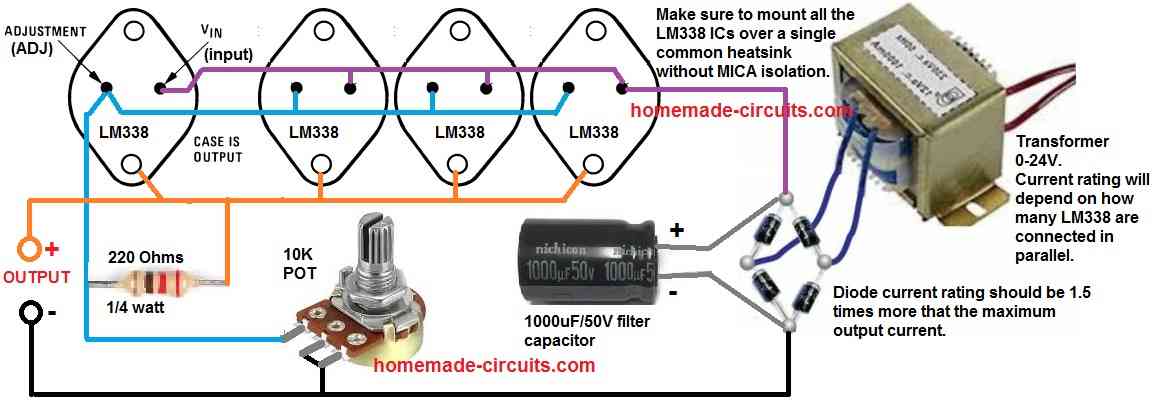
For fast charging of a 40 Ah L-Ion battery you will need at least 20 amp charging current which the shown circuit cannot supply.
If you are interested to use the same IC LM338 then you will need to connect at least 4 of them in parallel.
For complete details you can refer to the following post:
https://www.homemade-circuits.com/how-to-connect-lm338-ic-in-parallel-to-increase-output-current/
" rel="ugc">
Ok sir,i will try to build that circuit design..thanks for helping..i learn a lot from you..can i replace a transformer with 18v solar panel sir? I knew already that 220v source,i am focusing now with my solar panel.
No problem Vicferre, You can use an 18V solar panel, in that case you can eliminate the transformer, the bridge rectifier and the capacitor, just make sure to add a polarity protection diode with the solar panel.
In addition to this sir,,what transistor i must use as replacement for bc547 for fast charging of 40ah battery..i wanna build it in the same circuit design,only the transtor is replace.thanks,
Vicfere, the BC547 monitors the load current level and controls the LM338 accordingly ensuring the the output current does not exceed the load’s specification. For your application current control is not required because the 5 parallel LM338 in the previous design is internally current-controlled and will not allow more than 5 * 4 = 20 amps, which is just what is required for your application. So using 4 LM338 in parallel will restrict the max output current to 20 amps. If you want to make the charging still faster then you can add one more LM338 or maybe two more LM338 in parallel to make the current 30 amps for your 40 Ah Li-ion battery. Just make sure the output voltage is perfectly adjusted to provide not more than 4V per cell for your Li-ion battery bank. At 30 amps your battery may start warming up which again might need to be monitored and regulated appropriately.
…alternatively, you can also consider trying the concepts explained in the following article, which looks cheaper compared to the parallel LM338 option:
https://www.homemade-circuits.com/lm317-with-outboard-current-boost/
Hi Sir,
I dont really understand why do we need the other the tip36 and 2n222 transistors in design 6 with the integrate LM338. Thank you
Hi Sivuyile, the TIP36 and 2N2222 stage prevent the battery from over discharging. It cuts off the battery supply to the load when the battery voltage has dropped to a predetermined minimal level.
My wife is enamored with solar fairy lights for landscaping. However, commercial setups eventually fail in either the solar panel or the charge control chip. I am trying to design/construct my own box and reuse the still functioning LED strings. I am having difficulty finding a chip to control recharging a single AA battery and possibly control the LED string as well. I have attempted a design using a YX805A chip, but the datasheet is in Chinese. My best guess is that this chip can only handle 1.6v which is not enuf to power a string of LED. It seems to be good enuf for a single LED. How do I find a selection of chips that might do the trick?
Thanks for any assistance in advance.
YX805A cannot handle more than a single LED, so it cannot be used for driving LED string lights.
A single AAA cell will neither be able to power LED strings, unless it is a Li-Ion cell.
A 3.7V Li-ion appears to be the most suitable option for operating string lights with multiple LEDs.
If you can provide me with the LED string light specifications, I may try to figure out the appropriate circuit for the solar controller.
I need to supplement a 90 volt bank of solar panels with an AC generator, for shady days, on an off grid system. I currently charge the batteries with a 6000 watt AC generator but only need about 3000 watts.
Can I connect a diode rectifier to the AC output and use a variac to control the voltage to the 80-90v needed charge voltage?
Or what other options might be available?
Yes that can be done, additionally you can add a voltage regulator between the battery and the 90V DC from the diode bridge to fine tune the full charge voltage level to the battery. An example regulator circuit is shown in the following diagram: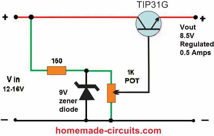
" rel="ugc">
You can replace the transistor with a TIP150, zener diode with a 90V 1 watt zener, 150 ohms with a 47K 2 watt
The AC source must be connected with the variac, and the variac output with the bridge, the bridge output with the regulator, the regulator output with the battery.
Hello Sir.
I have a solar system with 100W panels powering through a solar controller my lead acid 12v car batteries.
I want to add an emergency battery which consists of a power bank. It should not be using the controller. I thought to connecting a car plug charger (12V/24V->5V) directly to the solar panels, so it would automatically recharge the power bank over USB at day time.
Is there any issue to have the car charger all time directly connected in parallel to the panels/controller?
Thanks for your humble advice!
VESPUCCI
Hello Vespucci,
If your solar panel’s maximum output voltage is below the maximum tolerable input voltage of the car plug charger, then there’s absolutely no harm in keeping the charger connected to the solar panel all the time.
Just make sure the solar panel output voltage never exceeds the maximum tolerable voltage rating of your car charger.
Thanks so much for your help! You are best personality of the internet!
VESPUCCI
You are most welcome Vespucci.
Hello sir, im glad that im successful with my experiment for overcharged and over discharge protection for my 3.7v li ion battery. And thanks to your #5 transistorized solar design.im learning from you a lot.????..i sent you my circuit diagram in your email and its working…next request sir,can you please send me the diagram of pure sine wave inverter,12v to 220v inverter..i knew now on how to charge the batt,and so, inverter is my next project..im so tired of trying those fake inverter in YouTube,,and that was a reason why i ask you a design for this.thanks in advance for helping me..you are my great teacher now.????
Thank you Vicferre,
Glad the circuit is working for you.
Making a pure sine wave inverter can be a little difficult, instead I would recommend you to try a good modified inverter circuit whose output can be transformed into almost a pure sine wave by adding a few 400V capacitors.
The entire circuit can be found in the following post. You can try the 2nd or the 3rd diagram from the following post:
https://www.homemade-circuits.com/modified-sine-wave-inverter-circuit-2/
can you invent a short circuit protection for li-ion batteries as they are very dangerous when shorted
You can supply the Li-ion power to the load through a LM338 regulator circuit which will automatically ensure a controlled current to the load with short circuit protection:
" rel="ugc">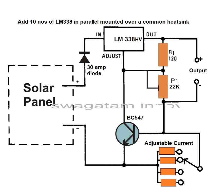
Hello sir,,i followed your design before and i proved thats it was working.I tried your #5 solar circuit design ( transistorized solar charger) and it was working for me,i was using d718 npn transistor and B688 for pnp. I dont have 11v zener for xy,so i made 2pcs of 5v zener in parallel and make it 10v…its effective sir,there was no load if the battery reaches 10v…then i parallel 3pcs of 5v zener to make it 15v for my xz because i have no available 14.6v..my question is that,is it ok to put this 15v?can it control the over charge?and if i have 14.6v zener soon, where can i put a led indicator for my over charge?so that i will know and prove that the solar stop charging because batt is full… thanks for helping me sir again
Thanks Vicferre, Glad the circuit is working for you.
However 14.6V or 15V is considerably high full charge level for a 12V battery, therefore I would recommend adjusting the zener value to 14V, because 14V is optimal overcharge limit for a 12V battery. For adjusting the zener value, you can add a few 1N4148 diodes also in series with the zener to fine tune the value to 14V. The polarity of the 1N4148 will opposite to the zener diode polarity. Sorry there’s no way to add an LED indicator in that circuit.
i dont have in4148 diode sir,but i have many in4007 diode.can i use it?thanks for response ????
Yes 1N4007 will also work…
Ah ok sir, thanks for additional knowledge ypu had given…i have to do a series of test with my experiment.well,i observed for over discharge protection and i prove that already.my next test is how many hours to full change my 12v batt from solar..my additional question sir is that,how many hrs do you charge using your own design?im asking this because i use other npn transistors that available to me… thanks again sir
Vicferre, The charging time will depend on the amount of current supplied by the NPN transistor to the battery. If its around 1/10th of the battery Ah, then the maximum hours will be around 10 hours.
What is that 1/10th mean sir?and what transistor that is fast charging that you can recommend?you’ re helping me a lot, thanks..i will let you know soon the result of my experiment..its compliments to you cause it comes from your design..????
1/10th is the result obtained by dividing the Ah rating of the battery by 10. If your battery Ah rating is below 10 Ah then you can use a TIP122 transistor
Ah ok sir, thanks
Engr. Good morning sir,
Please help,
1) I need a simple circuit diagram of solar battery charger using MOSFET..
Cut off at 14V..
Battery voltage 12V.
2) Secondly. How do I use Op-amp ICs for battery charge controller, like LM358 or LM741
Hello Sunshine,
1) You can modify the circuits from the following article for your 12V battery. Replace the 22K resistors with 1K and remove the parts from pin#7 of the opamp, and connect the pin#7 directly with the positive line:
https://www.homemade-circuits.com/make-this-48v-automatic-battery-charger/
2) For op amp battery chargers you can refer to the following article:
https://www.homemade-circuits.com/opamp-low-high-battery-charger/
Okay sir, thanks so much, let me work with the solution you provided for me..
I appreciate
No problem sunshine.
Good morning Sir!
Thanks for always being there to assist us. I love your circuits because they are relaible.
Sir, I have this questions.
1) As per design #5, the last or simplified version of the circuits which of the transistors work for full charge cut off, and which work for low voltage cut off?
2) According to another article you wrote on “4 lithium battery charger circuits” , you said we can charge a lithium battery with 14% of the rated voltage when there is a full charge cut off circuit. I wish to find out if I desire a full charge voltage of 12V using the above mentioned simplified circuit, can I use a zener (Zx) that is 12V(1.14) +.6 ? Considering that there is a full charge cut off
Thank you Ngang,
1) The transistor 2N2907 works like a low voltage cut-off switch.
2) The full charge voltage level of Li-ion batteries generally come in multiples of 4.2V. So For a 12V li-ion battery the fully charge level will be in multiples of 4.2V which will be 12.6V. However for better safety your can take the value of 12.4V instead of 12.6V.
So Zx value should be around 12.4 + 0.6 = 13V.
Please kindly help me to have comprehensive charging controller circuit diagram that suitable for 12v 40mah battery 12v 100mah 150watt solar panel
Thanks for you uncommon guide
The best idea is to use a LM317 based circuit, and adjust its output to slightly lower than the full charge level of the battery. It will keep your battery correctly and optimally charged.
Hello sir, i wanna try to follow the #5 solar circuit…can i use 7v or 6v zener in zy?please help me,i wanna know how to build that… thanks for reply
Hello Vicfere, the ZY value should be set depending on the low voltage cut-off threshold of the battery. What is your battery’s low voltage cut off threshold?
Thanks sir for the reply…i sent you message to your email…in addition to my question,can i use the the #5 diagram as a charger to my 3.7v li ion battery.i will only replace 5v or 4.1v zener to xz and 3v or 2.5v zener to xy…is it possible?im just trying to experiment ????. I want protection to my battery.thanks for response
Yes you can experiment with those zener diodes, but for the 3.7V lithium ion cell make sure the emitter voltage of the 2N2222 does not exceed 4.1 V. Check this before connecting the 3.7 V cell. Make sure to have a 1K resistor connected across the emitter/ground while setting the 4.1V. You can remove the resistor once the voltage is set.
Swag I just built No.5 on the list, this thing is awesome!! I am just using a cheap solar cell from a calculator and am getting 4 continuous volts, and the connected 18650 battery isn’t hardly draining at all, I currently am lighting a 1/2 watt LED and system is stable! . Thanks for this awesome circuit, I build a lot of your designs and postings and this one I think is better than a joule thief…..P.S. Swag in No.5 circuit is that a 47K trimmer pot from the transistor base into the voltage divider? Wasn’t quite sure, so I built it with a trim pot, not sure how to use it, and where would be the best place in the circuit to insert an LDR, so LED only on at night…thanks again Swag for all you do
That’s great Mike, glad you could build it successfully. Yes, the 47K is a trimpot, which must be adjusted to switch OFF the associated transistor when the battery has reached a low voltage.
For LDR connection you will need another BC547 transistor stage. Base to one terminal of LDR, other terminal of the LDR connected with the battery positive.
Also, base to ground through a 10K resistor.
Collector to the base of TIP122, and emitter to ground.
Ok sounds good thanks, why is it a 47K trimmer and not a 50K? Is there some relation to the circuit that you need 47K? Reason I ask is the case of trim pots I bought a while back (generic blue box shape) all are even number values….thanks Swag
Mike, The value is not at all critical, you can use a 50K preset without any issues or maybe a 30K preset, or a 20K preset etc they will all work.
Ok thanks Swag, have a great weekend
Hello Swagatam, I bought two 55ah batteries connected in parallel and 150w solar panel with solar controller on January this year. Now the batteries can’t be charged properly coz the just blinks even in a sunny ☀️ day some times. Do you have best solar controller circuit that I can replace it with…..about 60A and above? Pliz refer me. Thanks in advance.
Hello Morris, please specify the battery voltage and the solar panel max open circuit voltage.
Hello Swagatam, the batteries specifications are 12v 50ah each and the panel is mono 18v 150w.
thanks
OK great, you can try implementing the following circuit. Your two 50 Ah batteries in parallel will require around 15 amp current for charging optimally. Adjust the 10K preset such that the output voltage to the battery is not more than 14 V. Adjust this without a battery connected. Use a 1K ohm 2 watt resistor as the load (across the output) while confirming this output voltage.
" rel="ugc">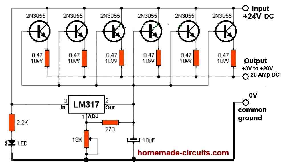
Hello sir, connecting the 1k resistor across output means that i should connect one end to positive and the other end to the negative? Secondly, will this circuit auto cut the the power to battery upon reaching the charge threshold?
Thanks
Hi Morris, The 1K must be connected across the points which is marked as +3 to +20 V and the 0 V ground line.
The full charge level of a 12V lead acid battery is around 14.3V, but since we are adjusting the charger output to only 14 V, so cut off is not required….the battery will be charged at 90% and will have a longer life, and can work without an auto cut off.
Ok thank you very much. Another question, can it be used to charge 12v battery for example if the solar is 300watts 18 and the battery is 300ah 12v?
Secondly can you refer me to another circuit of the same design that can be connected to solar panel 300watts 36v to charge 200ah 12v batteries connected in series if my inverter is a 24v.
Thanks.
The answer to your first question is, yes the proposed circuit can be used to charge your 300 Ah 12V battery from an 18 V 300 watt solar panel.
The answer to your second question is: You can use the very same circuit to charge your series connected 24 V 200 Ah battery from a 36 V panel. Just make sure to replace the LM317 with an LM317HV IC
Can the lm 317 be connected in parallel to handle the charging process or one is just enough? Thanks. And if the connection can be done in parallel what about the prest?
For 20 amp current you may require 20 to 30 numbers of LM317 in parallel which is not a good idea. Just one is enough if 2N3055 transistors are connected.
Hello Swagatam, I got an original lm317t. So in the diagram you have shown me i just connect 6 pieces of 2n3055 in that maner and one lm317. That will be just enough to charge the two 50ah batteries connected in parallel?
Secondly, if I want to charge a 24v battery with the 36v solar using the same circuit. Do I tweak the prest so that the output voltage reads 28v if in the case of 12v100av should be at 14v?
THANKS.
Hello Morris, yes that will be quite enough.
For 36 V you can use the same circuit but make sure to replace the LM317 with LM317HV. After that you can tweak the output voltage to 28 V using the 317 potentiometer.
In the circuit you sent to me, the 10k is not a preset it is just a potentiometer with three terminals like that of an amplifier for adjusting voltage?????????
Thanks.
Actually it should be preset or a trimpot so that the output charging voltage can be firmly fixed to a desired particular level.
I have a question sir,maybe it is considered as short circuit if we connect+3 to 20v output across 0v ground..if it work, what is the purpose of that?thanks
If you connect 3V across a 24V source, it will act as a short circuit and destroy the 3V source. There’s no purpose of this application.
Hi Swagatam. I am so thankful for these post. You really open my understanding of electronics. I am a mechanical engr. who loves building stuffs from mostly scratch.
I have an 18v solar panel ( don’t really know the power rating, it was initially used on a large street light) which I will like to use for charging three pairs of 18650 batteries in parallel while using them in series to power up a load. Can you please help me design the charging circuit capable of taking 10amp load with low battery and over change cut off. Thanks
Thank you Breno1,
I appreciate your interest.
I think you can try the last circuit from the following article. It should do the job for you.
https://www.homemade-circuits.com/opamp-low-high-battery-charger/
Thanks Swagatam for the response, but the I checked the circuit you recommended and it is a 12v battery charger. However what I want is a simple charger that will charge 3X 3.7v 18650 batteries in parallel from an 18v solar panel, while delivering 11.2v to a load in series. Please.
No problem Breno1, I will try to design it for you, however I could not understand what you meant by…”while delivering 11.2v to a load in series”
Do you mean you want to charge 3 X 3.7v 18650 batteries in parallel, and simultaneously power a load of 11.2 V, both from a 18 V solar panel?
@ Swagatam, you got the first part of charging the batteries in parallel. However, the load will also be powered by the batteries (24hrs), and it takes 12v Max. 9v min. So, while the batteries are being charged in parallel, they should also be delivering power in a series connection to meet up the voltage requirement of the load.
Thanks Breno1. Well, that can be very difficult to achieve. I cannot figure out how to set two configurations for the batteries, one in parallel for charging and second in series for powering the load. Sorry, no ideas for this configuration.
Thanks Swagatam for being straight. Though my main aim is just to charge the batteries safely while using them to power a load. My problem only got complicated when I read an article that says it’s not safe to charge those 18650 batteries in series.
If there is any way to charge them safely in series then I will go for that please.
Thanks again.
@Breno1, Generally speaking there’s no harm in charging Li-ion batts in series provided all are new and have identical characteristics. It happens very rarely that one of them alters its characteristics causing issues with the series charging. If you are still concerned then you can charge them in parallel first and then once fully charged you can connect them in series manually.
An automated version of the above operation can be extremely tedious to achieve.
@Swagatam, ok in that case I guess I need a 3 to 5 amp charger to charge them in series while connected to the load?
If so please recommend one you have designed or maybe modify one to charge 12vmax., 9v min. From a 18v solar panel.
OK, great, in that case I can provide you simplistic design which will always keep your batteries charged and in a topped up condition using a constant voltage and constant current. Meaning it won’t a cut-off at 12V and restore at 9 V, rather it will keep the batteries charged constantly at 12V, ensuring that the 12V is never exceeded or reduced.
I am suggesting this type of charger because building and setting up an auto cut off type of charger can be quite difficult for you, since you are not from an electronic domain.
Let me know if that’s OK with you.
@Swagatam Yes that will do. Thanks
@Breno1, You can try the following design:
" rel="ugc">
You will have to adjust the P1 potentiometer such that the points across the battery terminals get exactly 12 V. Please do this without connecting a battery.
Since 12 V is much lower than 12.6 V which is the actual full charge level of your battery, an auto cut off is not required, because the battery is never going to reach the full charge level.
@Swagatam. Thanks for the circuit. And I guess that 6A4 diode means 6.4amps diode?
You are welcome Breno1.
“6” indicates that the diode can handle a maximum average forward current of 6 amperes.
“A” typically refers to a standard axial lead diode package.
“4” signifies that the diode has a PIV of 400 volts.
Hi @Swagatam, thanks for the explanation. I still have one more issue though. How do I make up a 9.5v zener, as I can only find 9v zener to buy? Secondly you didn’t indicate the wattage of the 120ohm, 1kohm, and R3 as you did for the 470ohm resistors.
Hi Breno1, you can add a 1N4148 diode in series with the zener diode to convert it into a 9.5V. The cathode will face downwards and the anode upwards.
120 ohms and 1K are all 1/4 watt rated.
R3 = 0.7 / max charging current.
Max charging for your battery must be ideally 1.5 amps.
R3 = 0.7 / 1.5 = 0.46 ohms or simply 0.5 ohms
wattage = 0.7 x 1.5 = 1.05 watts or 2 watt, wire-wound type
Each of the battery is 3500mAh and I will double them before connecting in series (i.e three pairs in series).
Hi hope you doing well ????
What is the normal voltage, and current to charge a 12v 6A QLink
If it’s a li-ion battery then 3 amps, if it is an smf then 1 amp.
Juris
At the first circuit with IC7812 the rezistor is not needed because IC have Iq=6 to 8 mA to ground.
The voltage also may be set with to rezistors, one from output to Ic ground pin and other from Ic ground pin to ground.
Hello
Please can you help me on how to charge a 10,000mah battery 3.7v
Using 8v 8W solar panel
Hope to hear from you thanks
Hi,
8 W 8V signifies 1 amp current.
Even if you use a buck converter and reduce the 8V to 4.2V for the cell, still the solar current would be 8W / 4.2V = 1.9 amps.
1.9 amps is too less for a 10 amp Li-ion cell…..the current must be at least 5 amps for optimal charging, meaning the panel wattage must be at least 20 to 25 watts.
thanks for variety of charger circuit..
exiting awaits me.to do and expirements. your such a an electronic circuit expert.
mr. swag..
good evening..im one in a billion of your avid fan. and hope you can help me building an ebike charger circuit.
its a 48v. 32aH Carbon Graphite battery according to the ID mark product spec. i prefer very simple and cost effective. thank you very much and happy new year.
Thank you so much Michael, and Happy New Year to you!
I would recommend you the last circuit from the following article:
https://www.homemade-circuits.com/make-this-48v-automatic-battery-charger/
Sir, I want to design a circuit which can store energy from a little 6v solar panel into a super capacitor and when it reaches a certain amount of voltage (or gets full) it Suddenly releases its energy into a 500 mw , 3 to 6 v water pump for 6 seconds .
I would appreciate your help
Hello Khorshid,
you can try the following design:
" rel="ugc">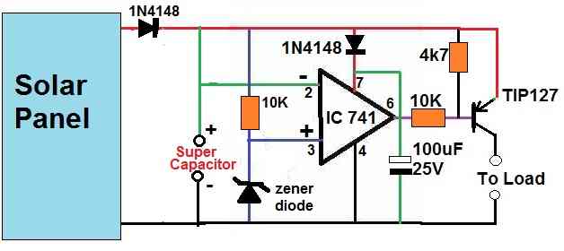
The zener diode value decides at what level you want to dump the capacitor to the load.
that was really helpful Swagatam
” for learning more from you ” , can we make it with just transistors ?something like transistor latch circuit with modification to start suddenly not gradually .
thank you
Thank you Khorshid,
Transistor circuit will not give a sudden discharge for the capacitor. For a sudden action only an op amp can work correctly. That is why I have used an op amp based circuit.
Please show me a circuit diagram to charge a 24v battery at 4 amperes ( with current control ) from a solar panel of which the output voltage rises up to about 50v ( at no load ).
Thank you.
Hi,
you can try the following circuit. Adjust the output to 28V to charge a 24V battery. Adjust S2 for selecting the resistor which corresponds to 4 amp output. This resistor value can be found by the formula R = 0.6 / 4 = 0.15 ohms, wattage will be 0.6 x 4 = 2.4 watts
" rel="ugc">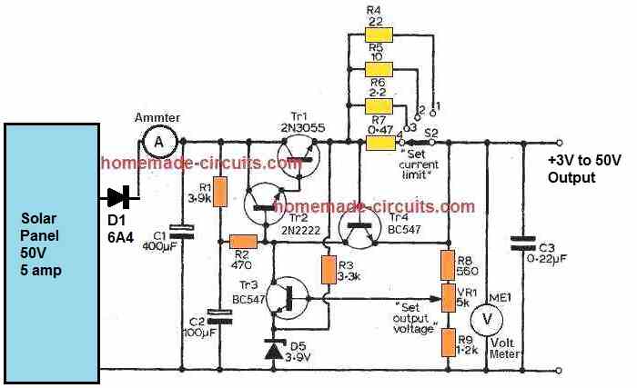
Good day Sir.
I wish to find out what modifications to do on the last circuit of project 5, in order to use it as charge controller for a 12V. 48Ah lithium ion battery pack
Thanks
Hi Ngang, are you referring to the following circuit?
" rel="ugc">
You can use it for a 12V 48 Ah Lithium battery but the ratings of the parts will need to be modified accordingly.
Yes Sir that’s the circuit I am referring to.
Which parts have to be modified.
Kindly help with the modifications
Thanks
For a 48 Ah Li-ion battery, the charging current will need to be around 24 amps/. For this you will have to replace the 2N2222 with a 50 amp Darlington BJT. You can manually create the darlington by configuring a 2N5684 50 amp BJT with a 2N2222.
The PNP BJT can be replaced with any 50 amp or 100 amp P channel MOSFET.
The other NPN transistor can be a BC547 transistor.
Select zener ZX such that it creates a full charge value across the points where battery is to be connected. Connect a 1K resistor across these points while testing this.
Select ZY such that the P channel mosfet just shuts off when the battery reaches its low battery level
Hello, loving this page. I have just started out into the Solar energy world. I wonder two things do you have any insights as to if its more efficient to buy lots of small solar panels and separate circuits or one big powerful panel to charge?
To give a bit more context I live in the UK and rent so cant put a big array on the roof. I was looking to take a few heavy hitters of electricity like my fish tank heater and pump onto solar/battery. As this is live fish ideally I would like to have the solar power to charge the battery, but when the power of the battery or solar panels is not enough to be topped up by the mains? maybe a status light to know battery charge and if the source charge is mains or solar?
Fish Tank Kit energy usage:
Pump/Filter: 6W
Heater: 100W
Light: 10W
Hi, thanks for this question, and glad you liked the above page.
Usually a single large solar panel is recommended which can be more convenient to install, wire, and use, and could be cheaper than many smaller units. Moreover this would allow you to use a single large battery for powering all the units together.
Nevertheless, if it suits you, you can use separate solar panels for separate loads, although wiring them up could be a little cumbersome.
In your specifications you have not mentioned the voltage rating of the loads, if you could mention them, I may try to figure out the circuit.
I am looking for a solar power charger with a 3-volt rechargeable battery that is connected to a load that is at 3 volts. the items I would like to connect to a smoke detectors, battery power digital clocks, and tv remotes. I am tired of buying standard AA and AAA 1.5-volt non-rechargeable batteries. I cannot find any circuit that just provides a constant solar power supply, most of the circuits have a shut-off when the solar cell stops charging and shuts off the power to the load.
could you please help me? thank you
I will try to help you, but before that I will have to know about the Ah rating of the 3 V battery. I guess the Ah rating of the 3V battery should be at least 5 Ah for powering all those items consistently. But a 3V 5 Ah battery might not be available??
A 3.2 V 6000 mAh battery is actually available in the market. However, I still might need to know the total wattage of the units that you would be operating using this type of battery.
Can you offer grab bàg kits for above solar charger circuits to diytea56@gmail.com (attn: dvm 56 recycler) please. Thank you
Sorry, supplying kits may not be possible for me, I can only help with the making of the projects
I have just discovered you site and enjoy your articles and gracias responses. I am interested in a simple solar panel charger for a 9v (probably Li-ion) battery. This configuration, which runs 24/7, will also be attached to a remote latching solenoid (outdoor irrigation valve at a local school and my home) over LoRa WiFi. LoRa requires about 130 ma per transmission and the solenoid requires about 20 ma. I was planning on using a 12v 3a solar panel, though am flexible on this. It looks like a LM317 will be the heart of this, but I am uncertain about the 24/7 impact. Activity could occur at any time. Any thoughts on a simple circuit to support this would be appreciated. I am also interested in seeing how long the battery will last.
Best regards,
Ron
Thank you for liking this website. I appreciate it.
I would recommend the 3rd circuit diagram from top. It uses an LM338 IC and will be able to handle the solenoid along with the WiFi current properly.
If you can tell me the full charge specification and the mAh specification of the battery, then I can suggest you exactly how to configure the LM338 regulator circuit.
A 12V panel might not be sufficient for a 9V battery since the 12V might drop too quickly as the sunshine depletes. Therefore I would rather recommend a 15V 3 Amp Solar panel for the purpose.
I am planning on initially trying the SHENMZ 9V Battery (claim 8.4 v, 1300 mAh). I should mention they also claim the battery can be charged using a USB charger. They also claim over charging protection, overheating protection, overload protection, short circuit protection, highly effective temperature control, and battery cell PTC protection.
I will also try the EBL 9V Rechargeable 600mAh Li-ion Batteries (8.2 to 8.4v). This does not have a USB charge capability but does have over charge protection.
They don’t have good documentation on charge times.
Sure, no problem. Please go ahead and let us know how it work. If you have problems feel free to contact us back.
Hello sir, l’m still confused because I went to different shops they told me that solar panel is rated in watts not in amps.Like you said,. So let assume I go for 20v/400watts or 180watts solar panel because I know in my area 400watts solar will be hard to find. And I can’t go for buck converter because the technique there is much, help me out.
Hello Youngking, for charging a 12V 150 Ah battery, you will require a minimum of 15V/15amp. However solar panel voltage and current cannot be constant because the peak sunshine will be only for a few hours. That is why i suggested using 20V 20 amp solar panel so that your battery can get optimal power even while there’s no peak sunshine. If you get a solar panel with lower current spec then your battery might take many days to get fully charged. So 400 watt solar is a must if you want your battery to get charged fully within a days peak sunshine.
Making and setting up a buck converter can be very difficult, are you sure you can build one?
Good day sir, I went to market and purcha se 12v/150Ah deep cycle battery. I went for 24v/200ah but it is expensive, I also went for solar panel which is 32v/30amp but they told me that solar panel is not rated in amps rather in watts. I’m confuse .sir with this 12v/150ah battery, what voltage and wattage of solar panel will I go for. Please clear me on this. I will be using one of your charger (4 step batter charger).
Hi Youngking,
for charging a 12V/150Ah battery you will need a 20V/20 amp solar panel. Or you can use a 40V 10 amp panel with a buck converter that will reduce the voltage to 20V 20 amp.
Wattage will be 20 x 20 = 400 watts, or 40 x 10 = 400 watts
Thank you sir, I will check the link
Hello sir l’m about to purchase 24v 200ah battery ,but my question is as foll ows. (1)- what type of solar panel am I suppose to buy that can fit this battery. (2)- suggest any circuit in your blog that can charge this battery so fast that is so simply to construct that is similar to mppt. Lastly what type of battery should I go for. I’m in west Africa.
Hello Youngking, You can buy a 32 v 30 amp solar panel.
making an MPPT like a charger can be difficult. Instead you can make a 4 step charger for charging you battery
Make this Fast Battery Charger Circuit
my company is in need of a bi-directional circuit board for a project we need developed. Can you email my personal email to discuss, please?
I can discuss it here, through comments if you don’t mind.
Yes i also need a solar control charger to charge my battery 100Ah by 12 volts using three solar panels that’s 80watts 100watts and 120watts as the China charge control are being blown off because of high current have arranged them in parallel I need the diagrams
You can try the following circuit for charging your 100 Ah battery. Remember you will have to adjust the zener diode value so that you get around 14.1V at the emitter of the tIP35:
I am trying out the first circuit wth the voltage regulator, but I only have .5 watt resistor
Enjoyable, straightforward and detailed. This homely approach is good for small homes and its use for custom generation of home electricity is well-established. Equivalently, for professional builders who are on the fast track, all-in-one pack / solar charger / regulator / inverter / is cheap, reliable, and lasts long, for industrial applications. Great work for starters.
Thanks very much, glad you liked it!
Hello sir, I really appreciate your efforts towards helping us students.
My question is, I have an LED that uses 12v 2.5w, I want to design a complete circuit and solar charger to charge my lithium ion battery. And above Circuits provide 1watts as the output, what can you say about it.
And sir, please how can I will explain how to design Electronics circuits with our knowledge of Electronics without using ones Circuits ????.
Thank you!
Hello Hassan, You can use an LM338 IC based charger for charging your li-ion battery as shown in the 3rd diagram from top.
You can learn designing electronic circuits by first building small circuits with proper understanding, and gradually going for bigger circuits.
I’m looking to build a simple solar battery charger for a 6 volt 250 ma panel I have that has a cutoff for when the batteries (6 volts) are full and starts charging them when the voltage drops to a certain voltage (5 volts?). I know I can use the 2N2222 with a zener diode for when the batteries are full, but don’t know how to setup the transistors to start charging when the level is 5 volts or so and continue charging until full charge.
If you want the cut off to happen at 6 V and charging to start at 5V then you will require a complex op amp circuit, which is actually not required according to me. You can simply use a LM317 IC based charger, and set the maximum output voltage to 5.9V. This will ensure that your battery full charge voltage never exceeds 6V, and the battery always remains topped up, and is never discharged below 5.9V.
Thank you
I’ll just take the simple route and just have it cut off once it reaches 6v with your circuit above.
The device won’t be used much so the batteries will pretty much be full at most times
Cheers
Sure, no problem, all the best to you!
Hi. Please I need clarity as regards MPPT solar charge controller you talked about using solar panel, selector switch and diodes.
Please how do I connect the selector switch to the diodes. Thanks!
Hi, you will need a multi-pole rotary switch. The number of poles will depend on the number of diodes used. The diode points will go the selector poles of the switch, while the + of the solar panel shown as arrow mark will connect with the center pole of the rotary switch.
Hi sir, I am a final year student working on Solar Powered LED Street Lighting with Auto Intensity Control. After reading this article, I would like to know is circuit no.5 or 7 more suitable for my project? I have a 6V 3W solar panel that can be used as the input voltage. Or do you have a better proposed circuit? Are there any modifications and things to note since I am using a smaller panel?
I would really appreciate your help. Thanks.
Hi Aaron, Since your solar panel is small, the circuit can be any simple design. I would recommend the following diagram from the 5) concept. The 7) concept is quite complex and lengthy so i won’t recommend that.
" rel="ugc">
Thank you very much sir. I will let you know if I have any further questions.
You are welcome Aaron!
I have used diodes in the out put of each panel and then made a common positive. I find that many people are not using diodes but directly making common of all panels. which is better? By using diodes I think
there will not be short circuit among panels. This was my idea.
Am I right?
J K barik
Diodes can drop around 0.6V that’s a drawback but it is safer, although there’s no possibility of a short circuiting between solar panel if there ratings are similar.
I have three solar panels(12V 100watts) connected in parallel. The short ckt current is 10Amp. But the charging current is 4amp. Battery is 150AH 12v. Current bat voltage is 12.2V . Why the charger not taking 9-10amp from panel? The charger is taking less current than available. I want to draw nearly 10A from panel.
is it possible?
Make sure the panel output is around 14V without load (open circuit voltage), only then the battery will consume the required current from it.
Hi Swagat ; wish you happy new year in advance.
It is more than 14V . The open ckt voltage without load is 20V around. It is amici smart 20A PWM controller.
What I think when the bat voltage is more than 12V the charger is reducing the ON-TIME and increasing OFF-TIME of PWM. It is not MPPT charger. The charger is not able to draw max-current. I feel it is not a smart charger and I have to think over it and make one based on constant current method. It is operating on voltage mode. Current is decided by battery. I may be right or wrong .
Hope you fine
all the best
Thank you JK, wish you too a very Happy New Year,
It seems I missed the point that a charger is being used in the middle. Yes in that case it may be the fault of the charger. Since the current output of the solar panel is quite less, it can be connected to the battery through a constant voltage circuit, such as LM196 or a transistorized circuit, which can be fixed at 14.5V, that would be enough for ensuring that the battery gets fully charged withing 14 hours of time.
Hi Sir Swagatam,
Good day.
Sir can u help me. I am trying to solve a rechargeable battery operated CCTV through solar panel. as i
understand how the system work, the system should charge the battery during day time and the CCTV operate through the solar during daytime and in battery during night time. As i check the battery using multi tester it still read at 3.5v each battery. there are two 18650 battery at 3700mA, the solar read at 3.5volts, i don’t know the how much is the amp. The CCTV is a portable wifi camera and will only work for several minutes and shutoff afterwards. if i remove the battery from the battery holder and put it back again, the camera will turn on and shutdown after several minutes.
if the battery is defective it should not read 3.5vdc. both battery is 3.5v when read using multi tester but still camera is shutting off. but if i remove the battery and put it back in again, the camera will turn on again.
Sir i hope you can help me with this.
Gil
Hi Gil,
I guess the batteries are connected in parallel, and the 3.5V reading is for each of the batteries? 3.5V means the batteries are significantly discharged, and with a load connected, the voltage might show even further drop….you can check the voltage with the CCTV connected for confirming the results.
The fully charged level of your cells should be at around 4.1V or 4.2V. For this you will need a 9 V solar panel, with a 4.1V charge controller circuit. Restricting the controller output at 4.1V will ensure no cut-off is needed, and the charging can continue as long as the solar voltage is available.
Goodday sir. Im trying to make a proteus simulation of the transistor controlled circuit the simplest one with zener diodes as limiter. I followed the circuit but the output only displays zero.
Earl, all the designs are tested, and all will work. The simulator softwares are not always correct…
desain mppt controler dengan kemampuan charging 50Ampere, itu bagaimana
Thanks very much Sir.
i saw the explanation through the link you gave.
sir can you help me with a circuit i can build for an automatic solar street light for off grid village community?
I will like it to be
1) completely transistorised
2) I have li-ion batteries (3.7 v) 18650 type and cell phone types.
3) I have 8mm LEDs (1/2 watt) available
4) solar panel size depends on you.(we have various sizes around)
5) it should be cheap and simple to be build.
6) Not really a big system. just an an appreciable brightness that can serve for village street light at affordable cost.
7) With explanation on how one can increase its capacity in the future.
Thanks for always being there for us.
You are welcome Ngang, you can try the following design for the specified appplication:
The LM317 is compulsory to ensure proper safety to the Li-ion cell.
Make sure to adjust the 4k7 preset, so that the LM317 output is exactly set at 4V or 4.1V which is slightly lower than the full charge level of 4.2V, and this ensures the 3.7 V battery can never get overcharged.
Similarly use a 3.3V or 3V zener for the ZY which ensures that the battery can never get over discharged below 3V.
To upgrade the power of the circuit, you can replace the LM317 with LM338, and replace the 2N2907 with TIP127.
Thanks very much Sir.
I have the following challenge:
1) the LM 317 regulator is not available here. but we have lots of npn transistors. please for a circuit that uses transistor in the place of LM317
2) I also need the automatic ON/off circuit I can use. With no relay and LDR. purely transistorized.
3) what number of 8mm LED can give an appreciable brightness for a village community solar street.
4) what should be the total capacity of the 3.7V Li-ion battery to run through out the night?
Thanks for being there
Hi Ngang, you can try the following circuit:
I have added the automatic day night ON/OFF for the LEDs in the above design
I have no idea how many 8mm LEDs can be used for your street light, you will have to experiment it yourself for getting the results. Same for the battery specs.
Zx zener should be such, which produces around 4.1V across the emitter/ground of the 2N2222. Zy can be a 3.3V zener
thanks very much Sir.
for Zx, can I calculate it as battery full charge + 0.6 ?
that is 4v + 0,6 = 4.6V
Hi Ngang, you can use 4.6 V for Zx, that will produce around 4 V at the emitter of the 2n2222.
also please check the diagram again since I have changed it slightly. In the new diagram the cathode of the zener diode ZY is connected to the battery positive instead of transistor collector
Okay Sir. Thanks very much
Hi Swagatam.
In the setup for number 9 above: Home Solar Electricity Set up for an Off-the-grid Living which I have already working, I want to ask just to be sure: What is the value of the diode used in the circuit? I used 1n5408. I don’t what know what you think.
Do i need to use a 6A or 10A? Or still use the 1n5408?
Thanks
Hi Joe,
the diode should have a current rating of more than 1.5 times the load current….so in your case if the output current is 5 amps then the diode must be at least 7.5 amps….however you can use a 6A4 diode and clamp it with a heatsink
Finally got a 0.039ohms resistor for R3 which increased the current. So i have LM338 X 2 connected in parallel on a heatsink, changed the R3 from 0.1ohms to 0.039ohms every other component is as specified: Transistor is B547, R1= 120 ohms, P1= 10kVR with 1n5408 diode. So are you saying I can use 6A4 diode with the present setting?
OK great, yes 6A4 is the diode that must be applied at the input of the LM338, however since the current is 10 amp, you will need two 6A4 diodes connected in parallel and clamped tightly together over a common aluminum heatsink
I observed that from time to time I will need to adjust the P1 10k VR to still get 14.1v as some times it drops to 13.6v or 13.8v.
Is this normal? Is the solar controller working well this way?
You can use fixed resistors instead of the pot, if you are finding the pot not very accurate with its settings.
You can try using the following software to roughly find out the resistor value required in place of the variable resistor.
https://www.homemade-circuits.com/lm317-lm338-lm396-calculator-software/
You can keep experimenting with the values until you are able to find the exact 14.1 V output
I also forgot to mention that I only could see a 6A4 and 6A10 diodes without metal, just like the normal diodes. Will connecting 2 of them in parallel be ok without a place to fix heatsink?
You can use an external clamping for the diodes through an aluminum strip or tin strip, as shown in the following example diagram:
If you are connecting two diodes in parallel then both must be clamped together in the above manner, this is mandatory otherwise one diode may conduct fully and other may not conduct at all causing the conducting diode to carry all the load and heat up.
I have a cheap 12v inverter and each time I connect this solar regulator to it directly it powers on but shows red light instead of green light. Although I have didn’t connect any appliances to it because of the red light.
What is the ideal voltage to power a 12v inverter?
Also when I set my digital multimer to 10A to measure the current, i get 0.12. What does that mean? Does it mean I have less than 3A from the solar regulator?
The maximum voltage that a 12 V inverter would probably tolerate is around 15 V. Without load the current will be minimal, but a higher input voltage than the tolerable limit of the inverter will cause it to trip OfF.
Good day Sir.
I want to make a li-on (18650) battery to run a 12v potable PA system.
The battery pack should 20Ah.
The li-on are 2000mh each
Kindly help me with the following
1) the series/parallel connection circuit for the pack
2) the charger circuit for the pack
Thanks Sir for being there
Hello Ngang,
You can put 3 of those cells in series, which will create an 11.1 V battery, or 12.6 V battery when fully charged. However the Ah capacity will still be 2 Ah or 2000 mAh.
To get 20 Ah you will have put 10 nos of these 12.6V batteries in parallel.
For a charger you can use the last concept from the following article, which is easy to build and yet is quite effective:
Battery Deep Discharge Protection Circuit
Hi Swagatam.
In the setup for number 9 above: Home Solar Electricity Set up for an Off-the-grid Living which I have already working, I observed that when I tried to measure the current, I get 0.02A.and I don’t think this is good. What do you think?
Also I connected two voltmeters, one across the solar panel to get the voltage and the other across the battery from the solar controller. When I connect the second one across the battery the first one drops the voltage from 28v to 15v. The second voltmeter still maintains 14.1v on average. Is this normal
Hi Joe, you can measure the current directly across the LM338 output and ground, that will tell you the maximum current capacity of the charger circuit….the actual consumption will depend on the battery condition.
Volmeters are supposed to be high impedance devices and connecting them across voltage terminals should not cause any problems….check the second voltmeter, may be it is faulty…
When I set my digital multimeter to 10A to measure the current across the LM338 and ground, i get 0.12 What does that mean? Does it mean I have less than 3A from the solar regulator? Or am I not setting the meter right?
It means that your LM338 is not working, or may be originally it is faulty..you can try disabling the current control and check, just to confirm the IC working
I will dismantle it but I must say that I am currently using a 10A diode since I will be getting the 6A4 diodes next week. Can the diode affect the current reading as I was using 1n5408 initially?
The 1N5408 will pass uptp to 1 amp current easily without getting substantially hot, from there onward the diode might start getting warmer….so the diode cannot be the problem according to me. The 10 amp diode might start getting hot after 5 amps or 6 amp limit
Hi Swagatam,
I have checked all my connections and even replaced the two lm338 ICs and yet the ampere is still low : less than 1A. Is there a special way to connect the lm338 in parallel other than joining Vout to Vout, Vin to Vin and Adj to Adj?
Could it be the solar panel is not giving enough current because I connected a diode to the positive wire and checked the current and it is still less than 1A.
The solar panel is rated:
nominal peak power = 190w
open circuit voltage = 46.2v
short circuit current = 5.42A
Max power voltage = 38.6v
Max power current = 4.92A
fuse rating = 10A
Max system voltage = 1000VDC
Hi Joe, the only problem with connecting such ICs directly in parallel is that one IC may conduct first and take all the load, while the second IC may remain idle…that is why I recommended to mount both the ICs over a common heatsink so that the heat can be shared uniformly across both the ICs allowing both to conduct uniformly.
You can try putting single ICs first in the circuit instead of two ICs together, and check whether the output gives 5 amp current or not, if both ICs produce no current would mean both the ICs are faulty.
You can also check the solar panel short circuit current in the similar way by connecting a 20 amp DC ammeter across the solar panel output terminals.
Since I have been wondering why the solar charge controller under discussion is producing little current ( less than 1A) and with the ratings of the solar panel I gave here, I must state that the solar panel is not installed on the roof but just by my window and still giving out about 28v to 31v. Can this affect the current output of the solar regulator?
Just wondering how four lm338 ICs I bought will all be faulty at the same time and even when I used lm317 it was the same result.
I am sorry for taking so much of your time.
A solar will require a peak vertical sunlight to produce the specified amount of full current output, keeping it near the window will probably not produce any current output.
Did to check the LM338 as I explained in the previous comments?
Yes I checked the LM338 as you explained in the previous comments and still same result. I used one lm338 and the result was less than 1A about 0.07A. I think it is the placement of the solar panel by my window that could be causing the whole issue. I will try taking it outside today just to verify. I will give you an update on this later.
OK, no problem.
As for 2) $1 Solar Battery Charger Circuit above, how best can I use this setup? I installed my 200w solar panel in such a way to give an average of 28v. I then connected 9 diodes in series. I guess i need to connect more diodes in series to get a safe charging voltage for my 12v 100AH battery.
I am only scared of overcharging the battery. What’s your advice on this for my solar voltage and battery?
You will need 23 diodes to drop the 28V to 14V which doesn’t look feasible to me, moreover the diodes will need to be rated at 10 amps each…..instead you can use another 12V battery and put them in series and connect the 28 V panel directly to the series connection.
Hi Swagatam.
In the setup for number 9 above: Home Solar Electricity Set up for an Off-the-grid Living which I have already working.
I set it up with two LM388 connected in parallel on a single heatsink and for R3 I could only find 0.1ohms as the lowest resistor. I looked for 0.04ohms but couldn’t get.
I hope this is ideal for 12v 100AH battery with a 200w solar panel?
As you suggested, I set the solar controller to 14.1v as output.
Hi Joe, yes your set up looks fine to me, however with 0.1 Ohm resistor the battery will be charged at 6 amp rate which can take a maximum of 20 hours for the battery to charge fully…nevertheless the charging will be safest and will give a long life to the battery…
I am sorry, I meant to say LM338 and not LM388. I used two LM338
No problem, I understood it
Hi Swagatam.
In the setup for number 9 above: Home Solar Electricity Set up for an Off-the-grid Living, I have it working now but tI have a little clarity:
To charge a 12v battery I need about 14.8v and I set the solar controller to 14.8v but when i connect to the 12v 100AH battery and check with a voltmeter it drops to about 13.4v. What do I need to do to charge the battery without damaging it?
Do I need to increase the voltage of the solar controller to give me about 14.6v when connected to the battery?
Thanks
Joe
Hi Joe, the charger supply will always drop to the battery level, while charging it, and will slowly increase as the battery gets charged….and 14.8V is too high, please reduce it to 14.1V
Thank you so much for the help
Hi Swagatam.
In the setup for number 9 above: Home Solar Electricity Set up for an Off-the-grid Living, I am currently setting it up. My question is this: can i leave the solar charger connected to the battery while I am away for about 3 weeks since the battery needs some level of charging always?
Or do I disconnect the battery and leave it till I come back?
What’s your advice for maintaining a deep cycle battery while travelling?
Hi Joe, you can leave the battery connected permanently without any concerns, but just make sure to adjust the charging voltage slightly lower than the recommended full charge level. Meaning if the full charge level of a 12 V battery is 14.3V, we must keep the setting at 14V which will generate optimal charging for the battery yet ensure that the battery is never over charged.
Thank you Swagatam. I appreciate you help. I set it up but with LM317 because i couldn’t get LM196 or 396 since i need about 10A to charge the 12v 100AH battery. I guess I need to keep checking for other alternative voltage regulators that can give 15v and 10A. But will it be ideal to use 12v regulator?
No problem Joe, alternatively you can also think about using 10 parallel LM317 ICs mounted over a single common heatsink.
Hi Swagatam.
In the setup for number 9 above: Home Solar Electricity Set up for an Off-the-grid Living, I wanted to ask if I can use it with a 500w or 1000w inverter, 12v 100ah battery and a 200w solar panel without a charge controller.
Just looking for a simple and quick setup that will be up and running.
Any other feedback will be appreciated.
Thanks
joe
Hi Joe, yes it can upgraded to any desired levels by suitably optimizing the controller, inverter, and the battery specifications.
The idea can be indeed a quick and foolproof design set up, although it may not be very compact and sleek.
What do you mean by suitably optimizing the controller, inverter and battery?
I have 2 inverters of 500w and 1000w. I can run any of them on 12v 100ah battery and will want to connect a 200w solar panel to the battery. That is why I am looking at this simple design with 3 resistors, a transistor and a regulatir IC.
I want to use this design No 9 as a charge controller. Can it work after i determine the value of R3?
Thanks
I also for got to mention that the foldable solar panel bag is 45w and 2.1A/3.1A
sorry, 45 watt cannot be used for charging 100 Ah battery
Hi Swagatam.
Thank you for your post on charge controller circuits. I have some questions:
1. Can you suggest or modify a charge controller circuit for charging a 12v 100ah battery?
2. I recently purchased a foldable solar panel bag. Can it charge a 12v 100ah battery.
3. Can i connect the foldable solar panel bag to a 1000va inverter?
4. Apart from charging some mobile devices, what else can i do with the foldable solar panel bag, because i got it to build a solar generator?
Thanks
Hi Joe, you can try the following two concepts for your solar charger
https://www.homemade-circuits.com/solar-charge-controller-for-100-ah-battery/
DC to DC Converter Circuits using SG3524 [Buck, Boost Designs]
Foldable solar panel is just like any other solar panel, and it can be used for powering any desired load depending on the their individual specifications.
Hi Swagatam,
Thank you for your reply. So does it mean that I can use either a solar charge controller or a DC to DC Converter Circuit or both. Seems they can do the say job of charginh a 12v 100ah battery effectively.
Also I wanted to know if i can convert a modified sine wave inverter to a pure sine wave using the EGS002 driver board. I have seen where some guys were describing the use of RC network circuits, but how can it be integrated in an inverter circuit?
Thanks
Hi Joe, solar chargers are generally of two types, one using linear regulator, or a shunt regulator, or an SMPS, out of the three options SMPS is the most efficient one.
Sorry I have not studied EGS002 specs yet so won’t be able to provide any suggestions regarding the results from this module at this moment…I will try to figure it out soon.
Your 5 design circuit has what appears to be a diode or led feeding the base of bc547, I’m not sure what it is as you did not label it and it’s color is red. Can you please identify it for me. I’m trying to build all you circuits to experiment and learn from them. I’m very excited to learn more. Thank you for your the posts
It is a RED LED, I am glad my posts are helping you to learn, let me know if you have any further questions…
Oh, ok. Sure, I can understand.
Would it be possible for you at least provide just the “bill of materials”
(I would later implement the Esp32 part), for an electronic project with
manual control like a knob for manual brightness control?
For example, let’s image I will go for 2x300w Led Chips to be used together
(same voltage, in parallel??):
2 x 300w/12v Led Chips
1 x 12v battery (what type / size would you use to reach up to 48hrs full brightness?)
n x solar panels (what type / size / quantity would you use to reach up to 48hrs full brightness?)
1 x wind turbine (let’s say 12v / 400 W)
n x Led (dimmable) Drivers?
…
(your help here too:
should I use mppt module? which one?
what other components like buck/boost converters modules, fuse box, led driver,
etc do you need Would I need?)
I know it would be almost useless without a strong electronic knowledge,
but that would give enough information for me to study the whole project
according to the suggestion by somebody like you with the right experience…
Many many thanks again for your time.
Kind Regards
Leonard
Thank you, I understand your requirements, I think I already have a related post which answers similar queries in details with formulas. Please refer to this link, I hope this post will help you to customize your specific needs:
Calculating Solar Panel, Inverter, Battery Charger
Hi Swagatam!
Very great projects here…
I am a student with experience in software and prototyping-boards programming field,
but without strong experience in the electrical/electronic field,
and would need help with a project very similar to some of yours.
I will go straight to the point, you can read my boring questions / considerations later (I hope!):
I got inspired by the current page, and by your other project here:
https://www.homemade-circuits.com/automatic-street-light-dimmer-using/
I would like to create a “Smart Flood Light” completely main-power-indipendent (solar + turbine + battery)
to monitor / control with my ESP32 board that owns WiFi onboard
(since I am good at the ESP32 / Arduino boards programming part).
I know this project is not easy / cheap to realize,
and since my desire is to create 2-3 “Smart Flood Lights” durable over the years
I am NOT on budget for this creations (but obviously I am not an business owner…)
I mean: I would like to choose the right components to create
something that would not die before the battery-pack end-of-life
(due for example to components broken by current / voltage peaks, or due to poor construction…)
I know your page deals with circuits, so don’t blame me if I am asking
help for an easy-to-go schematic made to assemble ready-to-use / easy-to-buy boards.
I think that the final result should be something like this (example):
?auto=webp&frame=1&width=1024&height=1024&fit=bounds&md=b029714a6136abb772656524e100f182" rel="nofollow ugc"> ?auto=webp&frame=1&width=1024&height=1024&fit=bounds&md=b029714a6136abb772656524e100f182
But… what I would like to deal with, are circuit-boards
(cheaper to buy, and I would integrate management by connecting my ESP32 circuit) like this (example):
" rel="nofollow ugc">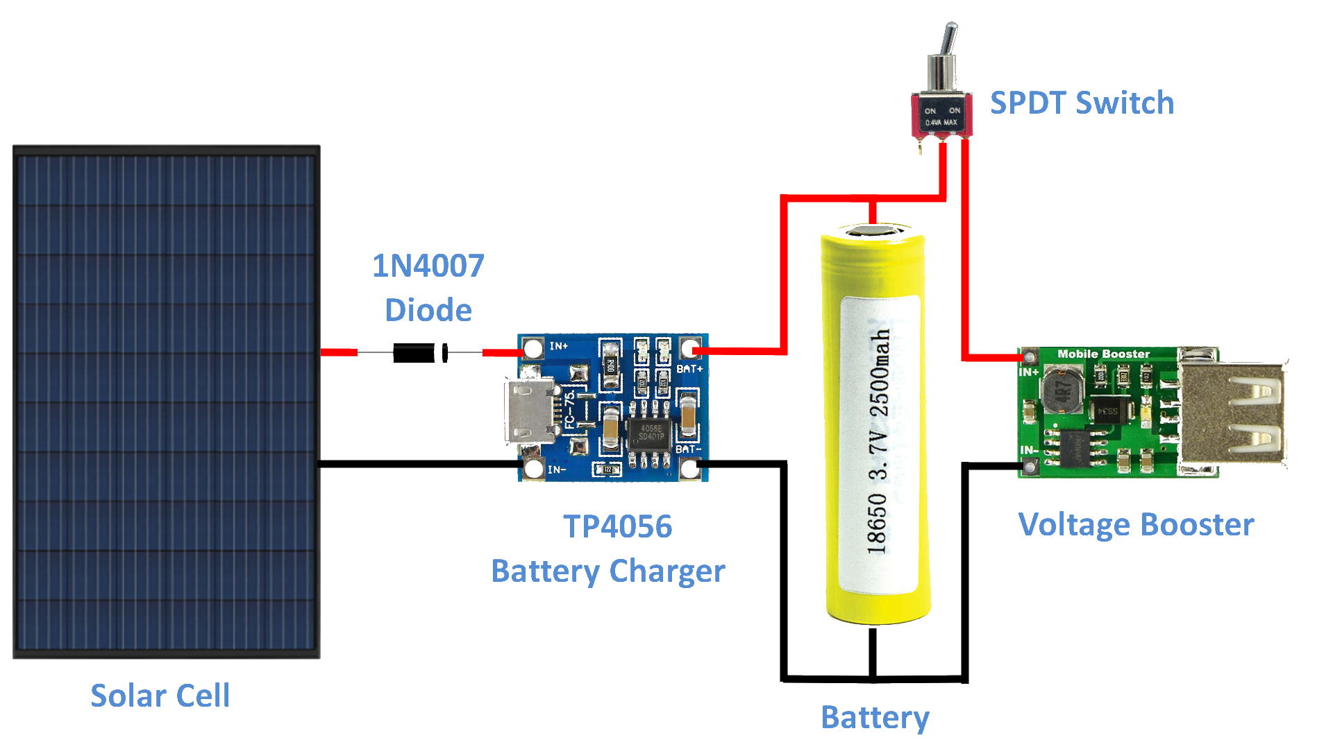
Of course… it would be a little out of scope for a website called “home made circuits”,
but I think this project would be very interesting for all that people like me
that have some place like his/her grandmother’s little house in mountain,
a garage, or a garden where there is always need to use a (strong) illumination.
So I believe a more complex / complete Solar + Wind powered system would be great!
And… you could take advantage from this, to create a modular project,
where you would explain (later) how to create/improve the “homemade circuits” you will suggest to use!
—
Ok, let’s start with my very long considerations of a student without electric/electronic experience
(I am sure you were smarter than me when a student!).
My “Smart Flood Light” would be a strong Led Chip Light powered by a battery attached to a Solar Panel + Wind turbine, so… ideally always disconnected from main current for almost all the time.
When I deal with Wind Turbine, I mean something like one of the common affordable-while-efficient solutions.
Classic Wind Turbine
" rel="nofollow ugc">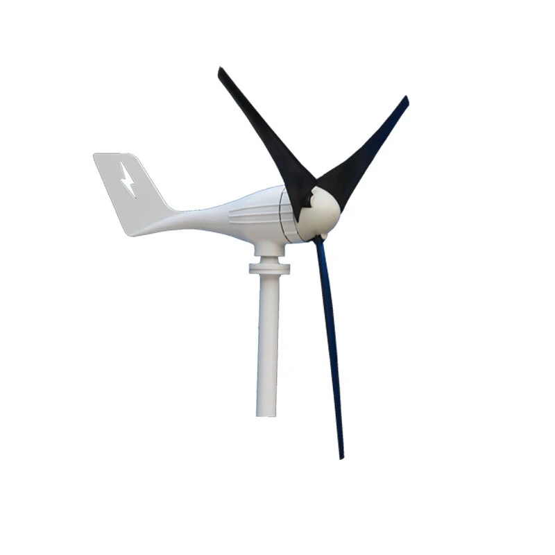
Vertical Wind Turbine (medium efficiency – medium cost)
" rel="nofollow ugc">
Vertical Wind Turbine (high efficiency – high cost)
" rel="nofollow ugc">
For every kind of “small” solution designed to be used at home,
today we have any size/power combination, 12 to 48v up to 1000+watt with costs from 90.00$ up to 1000.00$…
—
About the Led Chip.
Let’s say I would want to use a 3x100watt single led chip (or a 300w single led chip),
but possibly I could later point to an even brighter solution
(after understanding with your help the right principle to use for sizing battery, panel and for choosing the materials…
I am sure it will be possible to easily create a stronger Led Chip Light by adding multiple 100w led chip modules combined together).
The first thing I made after reading various posts online (and then stopping here on your website!)
was to skech up some schematics including ready-to-buy circuits solutions,
to achieve something like the commercial Solar powered Flood Light with integrated battery
(like this one: https://www.amazon.co.uk/dp/B07YWRFN5X/ ),
that commonly come with cheap built-in IC integrating IR remote-control + timer + light sensor
(as said, my “Smart Flood Light” would have instead WiFi control / power-monitoring, and additional Wind Turbine).
Other options are available on the market, for example with integrated design like this:
" rel="nofollow ugc">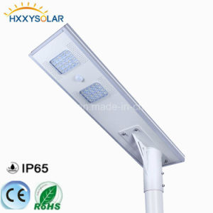
it’s exploded sketch:
" rel="nofollow ugc">
In my opinion, and for my mission (a long lasting light surviving to several cloudy days)
the integrated design is not suitable, because with just a solar panel
(and no wind turbine in the project, or no wind + no sun in bad days…) I would not have the possibility
to choose the solar panel position (since integrated in the enclosure).
But when trying to find the best solution to achieve a long lasting
street lamp on solar panel + wind turbine + battery
(let’s say up to – not subsequent – 24/48h only on battery, at maximum power/brightness)
I got very confused on what to assemble, and how to do that
(it was just clear that I do not want / need an Inverter,
since I am only going to attach DC Led Chip(s) to my Solar system).
—
Smart Flood Light features
Here you have the features I would like to get:
+ Dimmer the Flood Light from Zero to full-brightness via WiFi by controlling an attached Esp32 board (via PWM pins?):
In my mind I think it could be a good option to use 1x or multiple strong Led Chips like this one https://www.amazon.co.uk/dp/B01DFDKH2E/
to get a powerful / safe outdoor Flood Light, obviously mounted on appropriate heatsink, with thermal paste
(small fan to be activated on hot temperatures needed?).
But I do not discard to use a matrix of smaller leds (existing led board – no home-made soldered leds)
to achieve the same brightness, if that could give any kind of advantages.
+ Power the Flood Light both via Solar Panel (when there is still daylight), Wind Turbine (when there is wind)
and via attached battery, and (when possible, occasionally) via external DC power source,
while balancing the input power so that the light keeps the same dimmed chosen via the ESP32 (until low battery);
I imagine a scenario when for example I come back to my grandmother’s mountain house to check if everything is ok
(during the year, when there is nobody for a long time…), and I find the battery with low energy (unable to give power to the light):
I would like to be able to pass the current from my car (with engine on!) using the car battery cables I always have on-board,
or via a dedicated wire by using the car lighter… or finally via an AC-DC converter (like the ones used for laptop, so that I can ask my neighbor to give me some energy…)
+ Make the Flood Light automatically select the best power supply (always a DC power supply, in any case,
even if connected any additional source) without the need to use any physical on/off switch
(obvious? in some home-made configurations I found online, there was a configuration to manually select
a power-in source, but I can’t find a reason why…)
+ Monitor the in/out current/voltage (coming from battery / solar / external) using my ESP32 board
with built-in Oled Display, and transmit on WiFi via an embedded server page (that part easy to achieve for me).
+ Control remotely via WiFi the Led(s) brightness dealing with my attached ESP32 board (via Esp32 PWM pin ?)
+ Give the system Over-Current, Over-Discharge, Short-circuit protection… and adding
fuses / dc circuit-breakers where needed.
+ Implement a way to avoid full discharge of the battery:
it would be easy to discard Lead Acid batteries for this purpose, due to their 50% Depth of discharge,
but I do not know if the correct size battery of other technologies would have a good cost for a simple led light…
(I could not verify, since I am not able to size the battery Volts/Amps for a 300w Led Light;
the same for the Solar Panel and the turbine).
—
I know, it could seem a very long list of features…
but at the end, for a “small led” (up to 3watt) scenario, it could be considered like having
a led always connected to a “portable power-bank” constantly attached to a in-power source charging the power-bank
while using it’s own energy…
Only, in this case we would have 2 power sources (solar + wind) to be managed, and 1 additional rare power source
(DC current from my car or from my neighbor main-current.
(a lot of schematic are available on the internet for DIY solar-charged power-bank:
but… they are designed for low power leds / mobile phones small power – I’m lost when making calculations for high power leds…).
—
The main reason for that I am here asking for suggestions / help is because
I could not find any open-source solution like this online:
I could only find general-purpose DC and AC/DC solar systems, often costly
and with a lot of waste of energy if roughly adapted for this scope.
But I am sure to be in the right place… 🙂
—
The reason for that , my desire when buying parts would be to opt for existing / ready to use IC boards,
is because this way I can reduce soldering in my project to the minimum possible,
for a safe Solar Flood Light to be used outside (with the right external silicon seal).
Also, to achieve a long lasting Flood Light, I don’t mind to connect an out-of-enclosure battery pack
(I mean, it’s not mandatory for me to have a little embedded small battery pack to fit in the Flood Light enclosure,
I am fine with a standard scooter-size or car-size battery to be mounted separately and connected via a long-wire,
possibly with the best affordable technology (for the choosen size) to give (almost) no maintainance: LiPo? Lithium? Gel?).
—
About the connection diagram
My first questions (obvious?) were:
What Ampere / Volts would be the best choice for the battery (to match my needs)?
Also, for this kind of project (with a lot of charges / discharges) Is there a better choice than Lithium or Gel?
And what about the Solar Panel?
In the sample link from the Amazon Flood Light + Solar Panel,
that panel seems to be decent-size / medium-cost Polycristalline 50watt @ 10v Solar Panel.
It’s very easy to find that solar panel standalone: is 50w@10v a good choice for my purpose?
Or, what size/voltage/current should a Polycristalline Panel be for the case?
I thought that the first thing to do would be to raise the voltage to let a 12v battery be charged by the panel. Isn’t it?
Also, I found various Solar Power projects around (on groups / forums) inspiring mine, each with different features, using one or more of the following ready-to-use circuits:
fuse box
led driver
mppt
solar LiPo charger for LiPo battery (is it different for Lithium battery?)
LiPo voltage Tester (is it different for Lithium battery?)
BMS – battery management system (is it normally integrated inside a scooter / car battery? do I need it? it is the same as LiPo charger?)
Buck converter / Boost Converter
Etc…
I am not sure what of them are actually useful to bring my desired features
to a brand new project started from scratch:
some commercial ready-to-buy circuits have multiple features,
like short circuit protection + over current, but I would like to avoid
putting together circuits duplicating features while wasting energy with resistances or other passive components they ship…
Finally, just to not forget anything… what kind of wires are suitable for this kind of project?
Do I need 15/20 mm section cables like the ones to charge a standard car battery?
—
Ok, it seems you (and possible your readers) reached my ending lines: thank you for dedicating your time…
Could you share what’s your opinion?
I do not want you to explain here anything about the generic theory
behind this kind of projects
(very annoying for you, I know! – also, you already made it for your other projects…).
It would be already useful for me even a starting approach (bill of materials + pieces match list?) according to your experience so that I can easily put the electronic material together and
proceed with the order of the needed par,
and later come back here to post my progresses… and possibly with my version of the ESP32/Arduino code for the programming part.
—
I am very sorry for the confusion in my comment / request.
I am very excited to create something really “smart” with a little of customization (so, no Sonoff-like stuff here!)
and I am looking for someone with my same passion
sharing information on how to do the right thing… safely!
Hope you have enough time to help me,
and possibly other people wanting to explore / improve the same idea in the future!
My Best Regards
Leonard
Hi Leonard,
Thank you for the detailed explanation regarding your requirements and specification, it is much appreciated. However, it seems the project may not be possible for me, since it involves an Arduino programming, which is not within the field of my expertise. Also, I have not yet investigated the ESP32 system, so this is yet another aspect with which I am not familiar.
I truly wish I could help you to create and accomplish the project.
Nevertheless I wish you all the best and hope someone else will be able to solve it for you soon.
Hi Swagatam,
Thank you for your reply! I got all the components and have soldered up the #5 design on a PCB. When I apply a voltage (using my variable DC bench supply) I am not seeing any voltage at the LOAD or BATTERY terminals. I’ve traced things back and found that no current/voltage is making past TIP127. Do you have any suggestions?
Also, do you have any instructions on how to set the 47KR preset?
FYI–my battery is a 4 cell LiFePO4 @ 12.8V nom and I want to use this design to manage its charge as well as automatically switch on an LED attached to the LOAD when the sun goes down.
Thank you!
You are welcome Colin,
For the PNP TIP127 to conduct, its base BC547 BJT must be in the conducting mode, which can happen only when the other BC547 associated with the 47k preset stops conducting, which in turn will happen when the battery voltage has dropped near the full discharge threshold. This situation is indicated by the LED. Glowing LED indicates the battery is low, the TIP127 is conducting, and TIP122 is cut off.
The two BC547 actually form a low battery detector circuit. You can learn more about its setting procedure in the following article:
Low Battery Indicator Circuit Using Two Transistors Only
I see, thanks for that link. In comparing the 2 low battery sensing sections the main difference i see is the omission of a diode between the collector and the base of the two BJTs. I am using a 1N4148 in that place since I didn’t see a specific one referred to. do you think I should try removing it? Does it serve a protection function?
btw i did try pulling up the base of TIP127 (with a resistor connected to V+) and indeed saw a voltage appear at the Battery terminals. I haven’t connected my battery yet though. Could this be an issue too?
A battery will be required for observing the circuit operations. If the battery is low, will illuminate the LED and allow the TIP127 to conduct and begin charging the battery via the input supply. The input supply will also drop to the battery level and will slowly rise as the battery gets charged, until it’s fully charged, (the LED and TIP127 will switch OFF, TIP122 will switch ON)).
The two diodes at the bottom are for switching the two TIPs ON/OFF oppositely.
TIP127 being an PNP will switch ON with a negative bias at its base.
correction: TIP127 opens when I connect V- to its base via resistor.
Hi, Thanks for all this info–I’ve been reading through and learning a lot. I have one questions about the circuite diagram for #5: what is meant by the arrow pointing to the 47K resistor? I am wondering where to conect the base of BC547 (the left one) and am not clear on it. I also see in the PCB layout that the solder points imply 3 solder points on the 47K resistor component when I was expecting just 2, but maybe I am misunderstanding it. Thank you for any guidance you have!
Thanks, and glad you are finding the posts informative!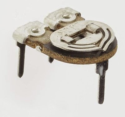
The 47k is a preset:
" rel="ugc">
The arrow is the center pin of the preset which is connected with the base of the BC547
OLÁ COMO VAI? GOSTARIA QUE ME AJUDASSE POR FAVOR. TENHO DOIS PAINEIS, QUE PRODUZ 600 WATS A 37 VOLTS,QUAL CONTROLADOR DE CARGA POSSO FAZER, PARA CARREGAR 3 BATERIAS 12 VOLTS EM SÉRIE, 36VOLTS? OBRIGADO.
Hi, 37V solar panel cannot be used for charging 3nos 12V batteries in series. You will need a 60 V solar panel for that.
You can use two batteries in series with a 37 V panel, using the following controller:
" rel="ugc">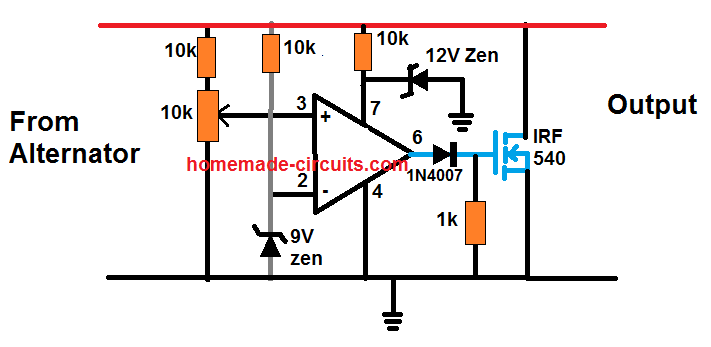
adjust the preset until the output reaches exactly 28V
Hello, how are you? Then if I connect the two panels in series, it will give 74 volts 9 ap and use 5 batteries 12 volts, will it be more enable? (5×14 = 70v) and in this case which controller suggest me? Thanks.
Hello, what is the Ah of the battery?
PENSO EM BATERIAS NO MÍNIMO 100 Ap, OU 115 AP. OBRIGADO.
You can try the following circuit:
" rel="ugc">
You will have to replace the MOSFET with a 100 V MOSFET, and adjust the 10k preset so that the MOSFET just switches ON at the 70 V mark
OLÁ,POR FAVOR, QUAL É O NOME DESTE CI? " rel="ugc"> OBRIGADO.
The IC is 741
Hello tutor, well done for the job. I need to bring up with some home made products like
1. A hybrid solar (200amh), wind (400amh) battery charger capable to charge 200amh to 1000amh (5*200amh) battery bank, having 5leds voltmeter and ammeter.
2. 3kva inverter to supply load of 2kva with an auto detect low power.
I hope you help me out with these circuits.
Best regards.
Hi Aanu, I will try to solve your queries as far as possible.
Hello Swagatam,
I arrived here on this page as I was looking out for solar circuits. I hopped on to your contact page to find an easier way to contact you, but as you have disabled comments on that page, I have to post mine here. And sorry for being off-topic on this comment here.
I am a very simple basic graduate in Political Sc. [1990 pass out] but I have some idea of these electronic components. I copied a circuit and used to make some Dancing LED lights, even a circuit that made my first amplifier. And I do some very very basic things at home just out of interest. I have no technical knowledge. I write you this comment with a hope that you can let me know where do I look for basic learning of electronics. I do plan to make a solar phone charger, solar circuit to charge a battery to keep powering a bluetooth device.
But as I mentioned, I have no clue on many things. I know you are busy, but I would be really thankful if you could provide me with a start place to learn the basics of electronics.
Stay safe and keep doing the noble thing that you are into.
Regards,
Sid.
Thank you Sid, I appreciate your interest.
Making a small solar charger is actually very simple, as you may have already seen in the above article.
You can make a solar cellphone charger simply through a single 7805 IC, as shown here:
https://www.homemade-circuits.com/how-to-make-simple-dc-to-dc-cell-phone/
You can start with this project first to gain some knowledge and practice.
For this you will need a 12 V 1 amp solar panel. One 7805 IC and heatsink for the IC.
Once your procure these two items you an jus hook them up and start charging your mobile phone. The capacitors around the 7805 IC are not necessary.
How are you? Please, which controller circuit, do you recommend me to use two panels, 305w each,
connected in parallel, using also 3 12v batteries in parallel? Open circuit voltage (Voc): 39.9V
Peak Voltage (Vmpp): 32.7V
Short-circuit current (Isc): 9.91A
Peak Current (Impp): 9.33A. Thank you.
Hi, how are you! I think you must connect the batteries in series, not in parallel….if your batteries are 100 Ah rated then you will not need any regulator. Simply put them in series and connect directly with the 35 V panel output. With 100 Ah battery you ca even connect 2 in series without any regulator.
Actually 3 in series will require 43V…so connect two in series with 32 to 36 V input. To ensure that the full charge level does not exceed 30 V, you can add a LM338 regulator, using two LM338 in parallel.
" rel="ugc">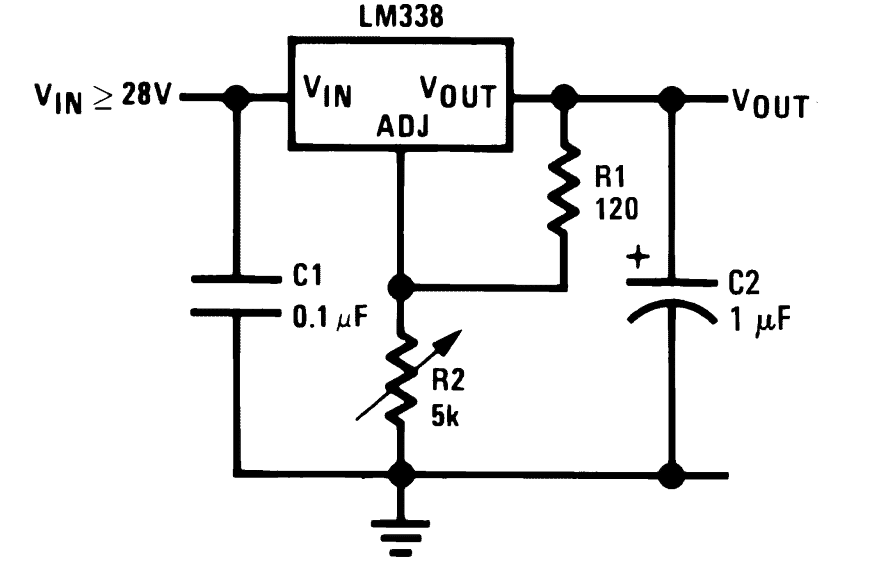
You can also replace the LM338 with a single LM396
How are you? And if I connect the two panels, also in series, it would be close to 65v and 9.91 Ap, connecting the 3 12v batteries in series. Could it work, not needing a controller? And what makes batteries warm? Thank you.
Yes that’s possible. but you will have to restrict the output to 14 x 3 = 42V. If the charging current is high over 20% of the Ah rating of the lead acid battery then the battery may start getting warmer, will also depend on the ambient temperature of the atmosphere.
example #5 (5) Transistorized Solar Charger Controller Circuit) above I don’t understand the PCB diagram looks to me like one of the BC547s is shorted in the center of the board. And in the circuit above the PCB diagram there are no resisters that come off the solar panel inputs but there is on the PCB diagram. Also, What is the 47K.
I have replaced the design with a new one, please check it now. The 47k is a preset
Thank you
Dear Swagatam,
Thanks for all the knowledge you are sharing though this site. I am looking to charge Li-Ion through Solar. In principle, can I use any 780X voltage regulator to feed my Li-Ion charge controller (Ex. TP4056)
Solar Panel => 780X Regulator => TP4056
Dear Chandra, yes you can use a 7805 or 7806 IC at the input
Halo, I find your article very helpful. However, I have a 100w solar panel with broken glass.it gives me voltage lower than 12v.what can I do to increase its voltage output since I don’t have money to buy a new solar
panel
Glad you liked it, however I am sorry I have no idea how to repair a solar panel with broken glass.
Thank you Sir. you have removed my all problems. As I am new to electronics I want to know from you regarding schottky diode. you are correct that you did not use this diode in your circuit but I want some information of this diode and by which diode it can be replaced. As you have mentioned earlier in your reply to me that if 0.7 volt drop is acceptable to me than I can replace with 4007 diode.
Hello AK Goel, a schottky diode is also a rectifier diode but it is designed to drop not more than 0.2 V across itself, whereas any other ordinary rectifier diode may drop anywhere around 0.5 V to 0.7 V. The second major difference is the switching speed, which is very high for schottky diodes compared to ordinary rectifier.
Thank you Sir. You have well explained to me regarding the schottky diode. You have explained it in a very simple way.
Now I am attaching a solar operated garden light which on after the sun set and off after the sun come back. This circuit is working fine but I have a problem which as under.
(1) there is no preset added in the circuit to vary the level of darkness at which the led
should on. Please tell which value of preset and where it should be added in the
circuit.
(2) How I can cut of the charging of cell 18650 used in the circuit, at 4.1 volt. Please tell
the cut off charging circuit and where it should be added in the attached circuit.
(3) I have a solar panel of 6 volt 100mah (70X70X3). can this solar panel can charge the
cell 18650 and if yes than how much time this solar panel will take to charge the cell
18650 2100mah.
Though it is not of your circuit even than I will request you to solve my problems like before and help me like a teacher. I will be highly obliged.
As there is no provision here to attach a circuit, I will send you through my email
Thank you AK Goel, 1) to control the darkness level, you can put a 10K preset between base and ground of the left side transistor in your diagram.
2) for auto cut off you can apply the following circuit
https://www.homemade-circuits.com/usb-automatic-li-ion-battery-charger/
3) 100mAh will not charge a 18650 cell properly, and may take many hours or days to charge it fully. The panel current rating must be at least 600 mA to 1 amp
Thank you Sir. You have solved my all problems. it is really wonderful that I got such a great teacher like. Thanks again
No Problem Dear AK Goel, you are welcome!
I have a solar cell operated fountain which works on 4.5v dc. The solar cell gives 6v. Now I want to ad cell 18650 so that when there is no sunshine, the fountain can still work. Please send me a circuit diagram showing the cell 18650 should be charged with solar cell in the sunshine and fountain switched off and when there is no sunshine then I can use the fountain with cell 18650.
After full charging of the 18650, the charging voltage should stop. Please send the circuit at my email addres or whatsapp no or tell me where I should see my required circuit. email id
akg1942@yahoo.com whatsapp No 9983937410, 8769044038
you can try the following circuit:
 " alt="solar water fountain with charger circuit" />
Adjust the 10k preset to get exactrly 4.2V at the output, the charging will stops as soon as this level is reached.
Dear and respected Mr SWAG. I am surprised to see that how quickly you not only replied me but You also sent the super simple trailer made circuit as per my requirement. Thank you very much SIR. This the first time I received a help so quickly that I can not imagine and secondly I found you who are very cooperative and helpful. I am a electronic hobbyist and some time I failed to make a circuit due to printing error or not properly explained of the circuit. But I am happy now that I found you and now I am sure that I will make the circuit successfully with your help if I am stuck. Now I have some more information regarding the circuit diagram you sent to me.
(1) Please give alternative transistor No for TIP 122
(2) Why Ic 7809 is used where as the solar cell with me gives only 6v. Can we stop the
charging of cell 18650 at 4v or 4.2v by using 6v solar panel only and removing IC
7809
(3) What is value of R 1 and D2
(4) In the circuit it has not been shown that where I should I connect my fountain.
Thank you dear AK Goel,
 " alt="solar regulator shunt type for charging Li-ion battery" />
the IC 7809 is used so that the output from the TIP122 stays constant at 4.2V. If the solar panel is directly connected without IC 7809 then the output will not be fixed unless a zener diode is used in place of the preset. But precise zener diode values are not available so zener option cannot be utilized.
If you want to use a 6 V solar panel directly for charging the Li-Ion cell with precise cut off at 4.2V or 4.1V, then you can perhaps apply a shunt regulator circuit as given below:
You will have to set up the circuit by applying a 6 V / 500mA from any rectified transformer supply, and adjust the 1k preset to get a precise 4.1V at the output side. Once this is fixed you can use it for the intended purpose
Thank you Sir for your quick reply. I was waiting for your reply to solve my problems. Your first circuit using ic 7809 is good and simple I will go for that. But you have not replied my other queries just as
(1) The alternative Tr no in place of TIP 122 as it is not available. Please give some
commonly available Tr. No. which can work in place of TIP122
(2) What is the value of R1 and D2
(3) Where at what point my fountain is to be connected in the circuit.
Dear AK Goel, if you use the 7809 circuit then the solar panel will need to be 12 V rated which can be a lot costlier.
However, it may be possible to replace the 7809 with 7806 IC and use a 9V solar panel.
There’s no replacement for TIP122, but you can build an equivalent using a 2N2222 and TIP31 in Darlington pair.
You can exclude R1 if the output voltage is adjusted to 4.1 V precisely, and use a solar panel having no more than 1 amp current.
D1 can be replaced with an ON/OFf switch so that output load can be switched ON/OFF depending on the sun light conditions. This output load could be your fountain
Dear Sir. I again thanks for your detailed reply regarding my problems. I tried but could not get TIP 122 and TIP 31 as where I am living is not well connected to the electronic market.
Please Sir can you design this circuit without using this TIP 122. Please design the circuit using commonly available transistor.
Secondly i want to know that how can I replace the SCHOTTKY DIODE. Can I use other
normal diode like 4007.
Dear AK Goel, you can connect any 1 amp to 3 amp rated NPN transistor, for example BD139. Preferably use two of them in Darlington mode.
Sorry I cannot see any schotky diode in my diagram. In general a schotky diode cannot be replaced with a rectifier diode, unless a drop of 0.7 V is acceptable to you from the 1N4007…
Good day Swag, please what are your advice for longevity using automotive battery for inverter, I know deep cycle are for inverter but cost too high. Please help out
Adeyemi, by longevity I guess you mean a longer battery life. It can be achieved by maintaining correct charging/discharging rates and maintaining proper battery fluids.
More info can be founds here
https://www.homemade-circuits.com/high-current-10-to-20-amp-automatic/
I want to run all my DC appliance directly from solar panel what type of circuit I have to use. please send me the circuit diagram
It will depend on the voltage specification of the appliances.
Thank you sir. Please tell steps of regulation.
Hi sankar, It is already explained in the above article, using LM338 or 7812.
Can I run DC fan , DC LED light directly from solar panel?
yes, but after appropriate regulation
good afternoon sir please can i connect three 7812ic chargers to a single 20w solar panel
Yes you can, as long as the max voltage of the panel is within 35V
Good day sir please is there a way the Imhotep free energy relay charger can be modified to charge a battery efficiently
Hi Abraham, first we need to verify whether the energy is really a free energy or acquired from the source itself? Because the coil will store energy from the source, so it cannot be a free energy.
Sir please can the 7ah solar charger using 7812ic charge 4 7ah batteries simultaneously
Yes you can, by adding 3 more 7812 ICs in parallel, just make sure to put them on a common heatsink.
hello sir, is about the second circuit that uses FSD ammeter for monitoring when battery is fully charged. my question is
1. can’t one use one of your circuit which is low battery indicator circuit that uses ic 741 in place of FSD ammeter.
2.if l’m using 12v 75ah battery upward what will be the specification of solar pannel to be use .
3. is solar pannel rated in amps or in watts.
4. according to ur caculation for R3 which is 0.7/ charging current
0.7/75ah= 0.00933 pls correct me if my calculation are wrong
5. how can one use the 10k preset to set the circuit.
waiting for your respond
Hello young king,
you can configure it as per the first circuit from this article:
https://www.homemade-circuits.com/make-6v-4ah-automatic-battery-charger/
Just set the preset for 14V and 11V cut off thrsholds.
LM338 will not support 10 amp.
You will have to use an LM196 IC instead.
solar panel is just like any other power supply source and will be rated in amps, voltage and watts.
75 ah is the charge/discharge rate, not the current.
for 75Ah battery you can use 10 amp charge/discharge current…therfeore R3 will be = 0.7 / 10 = 0.07 ohms
setting up procedures is already explained in the relevant article.
Please how can the circuit#2 be achieved automatically
If you set the output to 14V for a 12V battery, you won’t require an auto cut-off, and battery will be safe but slightly undercharged which is very good for the battery.
i am very happy with all these projects. what i need now is a simple way to construct my own solar panel,the simplest way pls. thank you
It would be better to buy a solar panel than to construct one.
Thanks for the quick answers. You are always well disposed. May God always enlighten you. The calculation of amperage: I = P / V. Lithium batteries should be charged with 1/10Ah. Right? Assuming that the solar panel at maximum produces 6V / 1W = 0.1666Ah. In 5 hours of sunshine would I charge an 800mAh battery? Could I be able to charge a cell phone with a step up module? In the case of battery charger and lighting LEDs, could a Joule Thief be used?
Li-Ion batt can be charged at full 1C rate meaning a current that may be equal to its Ah value, but this may heat up the battery and we may require temperature controller also…so the safe value can be 0.5C or Ah/2. At 160mA the 800mAh cell may require 4 to 6 hours of charging.
A smartphone will most probably not get charged with a 6V 1watt panel
Sir Swagan could guide me on two circuits?
The first would be using a 6V./ 1W solar panel. for simple smartphone charger.
The second would be with the same solar panel, but to charge 3.7V lithium batteries. with 4 high brightness LEDs. For lighting with this same battery.
Thank you very much in advance
Marcelo,
1 watt will not charge a smartphone at 6V. Your panel must be at least 1 amp x 6 V = 6 watts.
You can use the 1 watt panel to charge 3.7 v cells but it may take many days for them to get charged fully. LEDs current must not be more than 200mA for longer back ups.
Good day Swag, please how can I modify circuit #8 to have output voltage of 36v.
Hi Blessing, what is your panel voltage and current specs… please provide all the necessary specifications, I will try to help!
Maximum solar voltage 54.6v max current 6.4amps
yes, you can use it for the mentioned application…
Please sir, any modifications.
Many modifications may be required because the coil data is not verified. I can’t suggest much because I haven’t tested it practically, but the concept is correct. Alternatively you can try the following design which is a tested one:
https://www.homemade-circuits.com/5v-pwm-solar-battery-charger-circuit/
Hello Swag, please how can I charge a 100ah and 7ah batteries with same 150w panel.the 7ah will be for emergence lighting. Thanks
What is the V and I rating of the panel?
V-19.5
I-7.65
you will need a 14V/10amp buck converter for 100 Ah battery, 7 Ah can be directly charged through a LM338 charger as explained in the above article.
Can the two chargers be linked to the 1 panel
yes no problems.
Hello Sir. Can you provide a modified circuit of this so that it can be serve both a power source will the battery is charging and the battery as power source when the solar panel is not supplying power? Thank you.
Andre, you can use the first design from the following article:
https://www.homemade-circuits.com/solar-charger-circuit-using-transistors/
Does this cut off the charging process when the battery is full? It is not Simple afterall.
If you keep the full charge voltage level from the IC slightly lower than the actual value, then the cut-off action won’t be necessary and can be ignored
Sir
Can you just clarify. Using potentiometer P1, i set the output at 14V as measured by an ordinary multimeter. But when i connect a battery that voltage drops to 11.5 V. I am expecting the voltage reading to be maintained at 14V even when the battery is connected. Can you please help explain.
Thanks very much.
Pyke
Pyke, that is perfectly alright. As soon as you connect the battery the 14V must sink to the battery’s discharge level, and slowly as the battery charges the level would be seen slowly climbing until finally the 14V is reached…and then you can assume the battery to be fully charged, and disconnect it from the supply
To implement the above procedure we always make sure that the charging current is significantly lower than the battery’s Ah rating….
Thank you very much sir. I appreciate very much you prompt and informative response. Keep up the good work. I salute you
Pyke
you are most welcome Pyke!
Sir I have to charge 24v 14ah battery by solar panel I have two 12v 20w solar panel can I charge the battery by them if I can what is the circuit
Sharath, put the panels in series and check if the output is around 29V at peak sunshine, if yes then you can charge the battery reasonably well with those panels.
I read somewhere that the float voltage for lead acid battery is around 13.8 volts, and that with this voltage, the battery could be charged as long as possible, without causing any damage to the battery. What is your take on that sir?
that is correct!
Sir,
Please find below the link to my you tube video:
https://youtu.be/Hmjy6bfFXkQ
Please tell me what you think of it.
Once again thanks for your prompt help.
That looks great Vishwa! Thanks for posting
Sir,
Thanks for your valuable and kind appreciation.
Sir,
Thanks a million for your prompt help. May I use the schematic in my youtube video. I will mention the source and link to your website.
Thanking you for your time,
You are welcome Vishwa, you can use my circuit diagram in your youtube video with a reference to my site, let me know when you have posted it.
Sir,
As I am new to electronics I have listed steps to be doubly sure of the connection:
1. Positive of solar panel to positive of D1.
2. Negative of D1 to pin 3(IN) of LM338.
3. Pin 2(OUT) of LM338 to positive of D2.
4. Negative of D2 to positive of battery.
5. Pin2(OUT) of LM338 to top terminal of R1.
6. Pin 1(ADJ) of LM338 to pin 1 of BC547.
7 Pin 1(ADJ) of LM338 to bottom terminal of R1.
8. Pin 1(ADJ) of LM338 to base of P1.
9.Pin 1(ADJ) of LM338 to top terminal of P1.
10.Pin 2 (base) of BC547 to bottom terminal of P1.
11.Pin 2 (base) of BC547 to top terminal of R3. .
12. Negative of solar panel to pin 3(emitter) of BC547.
13 Pin 3(emitter) of BC547 to bottom terminal of R3.
14. Pin 2(base) of BC547, bottom terminal of P1 and top terminal of R3 to negative terminal of battery.
Thanks for your help.
.
Vishwa, sorry I can’t verify this because I am not sure which pins of BC547 you are referring by saying pin#1, 2 etc.
It is better if you could refer to the datasheets of the respective devices and check the pinouts yourself and then connect them by comparing with the diagram
Sir,
Thanks for your prompt reply. In my question I have mentioned the pin numbers as per the datasheet of BC547.
Thanking you for your time please.
OK, then everything is fine.
How much cost to make the circuit
Sir,
I want to charge a small Li ion 3.7V 2100 mh battery using 10W solar panel with following spec.Voc 10.43V, ISc 0.90A, Vmp 8.95V, Imp 0.82A. Will it work?
Parts used:
LM337
BC547
R1 = 120 ohm
R3 = 1 ohm
D1 = ?
D2 = ?
P1 = 10K
Can you please help and tell me if LM337 will work? What are the values for diodes? Thanks
Vishwa, yes it will work, just make sure to adjust the pot to get a precise 4V at the output and not 4.2V.
D1, D2 = 1N5408
Sir,
Thanks for your prompt reply. Wish you and everyone following you, a prosperous and healthy new year.
Thanking you for your time,
You are welcome Vishwa, and Wish you too very Happy 2018
can i use any resistor in this circuit?please tell the values of r1,r2,r3,r4.
please specify the voltage output that you prefer to have, or the battery specification will also do.
hello Swag,
i found this Solar, Wind, 2-Input Hybrid Battery Charger Circuit https://www.homemade-circuits.com/2015/09/solar-wind-2-input-hybrid-battery.html which is very simple not getting zener diodes in my area.
moreover reading from the above the modern highly versatile chips like the LM 338 and LM 317 i can get all the parts for my personal project so i want to make a request from the above circuit.
I have •Maximum Power: 265w •Maximum Voltage: 31.4v •Maximum Power Current: 8.44a
•Open Circuit voltage: 38.6v •Short Circuit current: 9.03a solar panel with which i can modify and use
but the other side is the shunt regulator from the wind mill if you could please add a circuit of Lm 338 and LM 317 with out zener diodes so i could use as a dual charger.
thanks.
Hello Nito, a windmill should be ideally operated with a shunt regulator only, but if you are interested to have a LM338 circuit in its place you can easily do it by removing the entire opamp stage and replace it with a standard LM338 voltage regulator stage.
Hello sir.
First of all let me say thank you for your fast replays.
The FSD ammeter and R3 are not available at the market. Suggest somthg instead sir?
Best regard
Abubakar,
you can connect a suitably selected automobile bulb in place of the meter, initially this bulb will glow brightly, and when the battery is fully charged this bulb will shut down….but this will happen gradually…so you can consistently get the idea regarding the battery charge level through the bulb’s intensity level.
hello sir , can i use this circuit for 6v solar panel and 4v battery….???
yes you can use it for charging a 4V battery from a 6V panel, but preferably the panel voltage should be 3V higher than the battery voltage
THANK YOU VERY MUCH FOR YOUR CIRCUITS AND EXPLANATIONS. I AM SURE YOU HAVE A WHATSAPP GROUP.MY EMAIL ID IS easokgeorge@gmail.com CAN YOU ADD ME TO YOUR WHATSAPP GROUP. IF YOU CAN GIVE ME YOUR EMAIL ID I SEND YOU MY PHONE#. THANK YOU ONCE AGAIN FOR YOUR GREAT SITE AND SHARING YOUR KNOWLEDGE EASO K GEORGE.
.
correction: it should be above 5K, preferably 10K for enabling a full range control
100mah
yes the circuit can be used for charging the mentioned battery, but I am wondering how a 100 mAH battery could be used for operating an inverter
Pls sir can this circuit charger 12volt 100amh Inverter battery.?
100AH or 100mAH??
sir, please also send schematic for 12v 2.2Ah lead acid battery charger using solar pannel and power rating of pannel.thankU
Sir, please send me circuit diagram of the solar pannel charger
You can try the second circuit from the following link:
https://www.homemade-circuits.com/2013/12/usb-automatic-li-ion-battery-charger.html
replace the 1N4148 diodes with a single 6V zener diode, cathode will go to pin#2 and anode to the ground
thank U Sir
Sir, what will be the crt. of the charger
what is CRT??
its a circuit(ckt.) by mistake crt.
Hello Sir,
I have to charge 12v 2.2Ah Li-Ion battery using Solar pannel, will u suggest me what type of solar pannel should i use and what is the power, voltage, and current rating of pannel…
Hello Gaurav, you can use a 15V/1amp solar panel for your batt.
Sir Swagatam can this circuit charge a lithium ion battery? Im looking for a solar charger that can charge a lithium ion battery pack with overcharge protection .. thank you very much for your help sir..
Paul
Paul, yes it can charge a li-ion batt but you'll need to monitor the current level in the given ammeter and switch off the charging process when the meter needle drops to zero….initially it will show the charging current of the battery and gradually begin dropping…
for an automatic cut off you can opt for the second circuit from this article:
https://www.homemade-circuits.com/2011/12/how-to-make-simple-low-battery-voltage.html
Sir what's the meaning of the ground symbol between battery negative and R3.
should we connect it to pv negative by a separate connection?
it's the battery negative….don't bother about it, just make the circuit as given in the diagram…
hi sir,
im having a 12v 1 Ah battery(3*4v) and series pannel 6v+6v+3v = 15 v>
is it possible to charge the same with this circuit ??
Hi emil, yes you can use the above LM338 circuit for charging for battery…
sir could you please suggest any circuit for 1Hp single phase induction motor speed control, using PWM or variable frequency method.
Hi Shankar I think you can do it by using a standard fan regulator unit, by replacing its existing triac with a 40amp triac such as a BTA40A/600, you may refer to this article for more info:
https://www.homemade-circuits.com/2012/03/how-to-make-25-amp-1500-watts-heater.html
Hello Sir. I want to know if it is possible to charge a 12V 7A battery using a 9 V 3w solar cell using your circuit.
Thanks in advance.
Hi Garry, by what name have you sent the email? I could not find any
hi sir i sent an email,need your help for my project,very very tnx sir
sir do you know any current amplifier circuit that i can use because the output current from the circuit is very low, i recorded 200mA as the highest current that the circuit can supply so far which is not enought to fully charge the 40Ah battery. The panel is rated 100W and current peak is at 5.61A but it only supplies about 400mA input current to the LM338.
Nine, a current amplifier is out of question here….if your 100 watt panel is producing 400mA simply means it's faulty or something may be wrong with the connections….or if this happening after the LM338 IC stage would indicate a faulty or incorrectly wired LM338 IC….please check all these individually to confirm the results.
sir i'm still thinking if I should remove the relay in the circuit.. the setup now is that the relay serves as a switch for the sensor circuit, if the battery is in charging process the relay trips and the sensor is disconnected from the circuit so the charging current is divided to the battery amd relay.. if I do remove the relay the charging current will be divided to the battery and sensor circuit, however, the sensor circuit is composed of a voltage regulator, ATtiny mmicrocontroller, op amp, and a power mosfet for the LED.. I know the sensor circuit is quite large so it will really require a sufficient amount of current than the relay I think.. what would you do here sir?
Nine, the sensor circuit is not supposed to consume more than 5 to 7mA and the relay not more than 30mA….so it's your wish now whether to use the circuit or not as per the application needs.
thank you sir.. so I will connect it in parallel then and remove the relay now
also sir is it ok if I connected a dark sensor circuit parallel to the battery so the led lamp will automatically switch on at dusk? If yes, will it affect the charging process because the output current from the above circuit will be divided for the battery and sensor circuit?
yes it's possible, it won't affect the charging process since the current consumed by the system will be relatively smaller.
sir is that why the battery is dropping so quickly? also we also connected a regulator ic which is 7805 to bring down the voltage to 5V for our microcontroller, is 7805 also a factor why the battery is dropping? thank you sir
yes if the battery is not charged optimally, it will drop quickly, 7805 is not responsible for this at all.
hello again sir! i finally implemented the above circuit. I used a 100W solar panel to charge the 40Ah battery. First I used the battery to power the lamp and it dropped to 8V. I think the charging works fine because from 8V, the circuit was able to charge the battery to 13V. The problem now is that the battery is quickly draining, dropping to 8V after 2 hrs of supplying power to the 24W led lamp. The lamp still stays on but I think that should not happen to the battery dropping off too quickly. What would be the problem here?
Hello Nine, you must charge the battery up to 14.3V, for ensuring 90% charging….13v is not the optimal level for a 12V batt.
sir i'm a bit confused.. i followed all the calculations and it said I need at least a solar panel of 30W and a battery of 20Ah.. but you said before for a 24W lamp I will need a panel of greater than 50W and a battery of more than 40Ah.. sir please explain thank you
you might have calculated wrongly….a simple way is to divide 30 by 12, it gives 2,5A, how can a 2.5A charge a 40AH battery within 6 hours, it would take about 18 hours at that rate.
a 24 watt lamp will consume 24/12 = 2amps…so with a 40AH batt we get 40/2 = 20hours ideally but it would be just approx 12 hours practically
so you will have to charge a 40AH battery fully for sustaining a 24watt lamp for about 12hours
ok now I understand thank you sir.. anyways sir can I request for your insight on how to calculate the approriate battery and solar panel for our 12V 24W LED Lamp that should stay on for a whole night.. I just wanna have a concrete basis for picking the battery and panel..
you may refer to the following article for a detailed info:
https://www.homemade-circuits.com/2013/05/how-to-calculate-and-match-solar-panel.html
then it makes sense when the output voltage changes because the input voltage gets lower from the solar panel.. sir do you have any more circuit that can produce constant output regardless of the changes in the input?
….the output should be perfectly constant even if the input fluctuates widely but it should not be very close or lower than the intended load voltage
sir what should be the minimum input voltage from the panel so I can constantly produce 7V from the circuit using lm317? and what should be the minimum input voltage from the panel so I can achieve 14V from the circuit once I used the lm338?
It should just 1V higher than the required output, meaning for 7V output the input could be 8V…and for 14V output it needs to be 15V minimum
it's okay sir.. I just tried to put the panel under outdoor light even if it's cloudy.. now i'm getting up to 12V from the circuit.. I guess it makes a huge difference when you're testing it indoor.. now the problem is the output voltage keeps changing whenever I move the panel from different locations.. I adjusted the circuit to produce 7V but it keeps changing when I move the panel.. I thought this circuit will produce constant voltage once I adjusted the potentiometer regardless of the varying input voltage from the panel.. sir what is wrong here?
Yes the IC must produce a perfectly constant voltage regardless of a changing input.
Check and confirm the circuit first with a variable DC power supply and see the response.
sir i'm having problems with the circuit.. I tried. to construct this circuit in smaller scale so I bought a 12V 10W solar panel to charge s 6V 4.5ah battery. I used lm317 and I eliminated the transistor part because I want to see the output voltage first. But then the output voltage i'm getting is only up to 1volt. I checked the output voltage from the solar panel alone and its 7V. sir what am I doing wrong here? I haven't tried to put the panel under sunlight because it is cloudy here so i'm just testing it under indoor light.
Nine,
That's impossible unless you have done something wrong with the connections or have a faulty (duplicate) chip.
You may refer to this article for a better view of the concept:
https://www.homemade-circuits.com/2012/02/how-to-make-current-controlled-12-volt.html
sir what is the specs for the two diodes?
twice of the charge rate in amps
Hello sir. I would like to use the above circuit to charge a 3.7V 1500mAh mobile phone battery, with a 12V 5W panel. Can you please let me know the changes needed to be done to the circuit?
Hello LNB, the above circuit may not be appropriate for your application, you can try out the following instead:
https://www.homemade-circuits.com/2012/08/simplest-dc-cell-phone-charger-circuit.html
Make sure to replace the 9V zener with a 4.7V 1 watt zener and connect the 3.7 cell across the outputs indicated with a charger pin.
Hello, sir. I would like to thank you for your reply, and for the alternate suggestion. I just wanted to ask, couldn't I adjust the pot P1 to get 5V (4.2V battery's fully charged state voltage + 0.7V diode forward drop), and select R3 to get 10% of my battery's mAh?
Hello LNB, yes you may do it, please refer to the following article for the exact info
https://www.homemade-circuits.com/2014/12/12v-dc-solid-state-relay-ssr-100-amps.html
for Li-ion batts, 1/10th AH charge rate is not critical…you may apply even upto 1C rate that's equal to the Li-ions AH rating…
Hello sir. So, for a 1500mAh battery, i can use a 1.5A charging curent rating safely, as long as i remove the battery immediately after charging?? The only limitation is from the solar panel, isn't it?
i'm determined to use your circuit so what should be the input voltage and current for lm338? and is there anyway to adjust the output current?
input voltage is 32 max, current doesn't matter it can be anything as long as volatge is within 32V.
the max output current can be set anywhere from 0 to 5amps by selecting different values for R3 as per the calculations
how bout a 60- 80 watt panel?
Yes, you can try it out, might just work.
what if I used a battery of 45Ah or 50Ah?
yes will do but a 50 ah battery will need a higher wattage solar panel for fast charging, it will charge very slowly with the existing 50watt panel
what do you suggest sir that I do to make it longer?
There's no way to increase the back up time, unless another battery in parallel is used…. but that will require upgrading the panel to 100 watts.
for the current rating of the solar panel (12V 50W), what do you suggest I use sir? a 12V 40Ah lead acid battery or a deep cycle battery?
note: the battery should be able to supply enough power to the LED lamp for the whole night (12 hours at most). thank you sir
deep cycle batteries are also lead acid batteries, so you can use a 40AH lead acid battery for the said purpose.
The mentioned 24W lamp can be operated for not more than 6/7 hours at stretch with a fully charged 40AH batt.
sir this is the current setup of the project..
12V 50W solar panel to charge a 12V 40Ah lead acid battery, the load will be 12V 24W LED lamp
what are your thoughts about these adjustments? and can the circuit above can charge a deep cycle battery? thank you so much sir for answering my questions
yes a 12V 50 watt panel can be used for charging a 12V 40AH deep cycle battery, but will require around 10 hours to get fully charged.
a 12V panel during peak should be producing 15 to 16V, so according to me you can connect it directly with the battery through a 6A4 diode…the above circuit may not be required.
sir if that's the case, can I still use the above circuit? by the way it's 12V 55ah battery
for a 12V battery a 50 watt panel can be used, but the panel peak voltage should not be above 15/16V for an optimal response,
yes the above circuit will just fit in.
sorry sir it's a 12V battery
ok sir i'll research more on that.. anyways can I use a 24V 50W panel to charge a 55Ah 22V battery, by the way the battery will supply a 12V 45W LED Lamp.. what's your opinion about this sir?
Nine, you will require a minimum 125 watt panel for charging the specified battery….50 watt will not do it satisfactorily.
goodday sir what kind of ic will i use to charge 12v 9ah lead acid battery from solar cell of 12 volt 10 watt
GEA, 12V solar panel will not charge a 12V battery, It should be around 16V solar panel, with 1 amp current
correct me if I'm wrong sir, but you're assuming that the battery is rated @10 hr. I will be using a battery that will be rated @20 hr, so i can use a maximum of 100Ah because 100/20= 5A, which is the maximum output current of LM338..
I don't know if a lead acid battery can be charged at AH/20 or C/20 rate, so I can't say much about this calculation…C/10 is considered as the minimum optimal range for charging lead acid batts.
sir what is the maximum Ah that this circuit can handle? and can you teach me how to add an overcharge protection circuit to this one because i need the circuit to automatically stop the charging when battery is full.. thank you
Nine, the LM338 IC used in the circuit can handle up to a 50 AH battery for charging.
sir can you explain the role of each component in the circuit? i wanna understand how each of them function.. and how did you come up with the computation R3=0.7/chg. current? thank you so much sir!
The upper resistors are as per the IC datasheet…the BC547 is responsible for grounding ADJ pin of the IC and disabling it when an over current is sensed, and this happens when the potential across R3 exceeds 0.7V which is the switch ON (saturation) voltage of the transistor
Hi sir
I wanna ask if i can use this circuit to charge a 12v 40W lead acid battery ti powerup an LED lamp during the night. I'm planning to use this for a streetlight.
Hi Nine, did you mean a 40 AH battery? Yes you can use the above circuit for charging a 40AH batt, make sure to put the IC LM338 on an adequately large heatsink
Hi sir,
I realised the circuit of this article but I can manage only the voltage at the output with the potentiometer, not the current. What could it be wrong? I didn't put the R4 and I switched the multimeter as ammeter and connected it in series the output of circuit with the battery.
Hi Daniele
R4 is not required anyway, so the current limit will still work for you depending upon the selection of R3
…the pot is only for varying the voltage not current, current can be managed by altering R3 as explained in the article.
Thanks, I really appreciate your help, the circuit works, finally! 😉 I have just one more question: there is any ways to evaluate the charging current? I have two batteries in parallel, one is 10Ah e another one 4.5Ah. The solar panel produce 1,7A and the R3 is 0.47ohm. I guess I made the correct calculation but I would check the real current that pass on the circuit. Any suggestions? Thanks in advance for any answer 🙂
Thanks Daniele,
Usually it's AH/10 for lead acid batteries and AH/1 for Li-ion batts, but if you have two batts in parallel with different AH rating in that in case you may have incorporate separate current limiting circuits for each batts.
You may have to make two of the above circuits, and calculate R3 separately in order to feed the respective batts…the ground will be common for both the circuits.
actually i want to make charging my 24 volt 1.5 Ah battery to supply 24 volt, 600 mA STEPPER MOTOR…..
is this possible from 12 volt 250 mA solar panel using 12-24 volt boost converter???
No it won't, it's the same situation as previously explained…
ok… so according to you i should connect two 6 volt, 250 ma panels in series… then i will get 12volt 250ma…. am i true sir??
yes that will do but the voltage will need to be at least 14V to initiate the charging….
thank you for your reply…
but sir if i will place a boost converter in between solar panel and battery…..is it true??
….for that your solar panel supply should be rated to generate at least 1amp output, 250mA will not do.
have a good day sir!!!
plz help me about my question that, is it possible to charge 12 volt 1.5A battery from 6 volt 250 mA solar panel?????
good day Tejas,
No that's not possible, the voltage should be minimum 14 V
Sir, i have 70Ah 12volt battary and i'm about to buy 100Ah solar panel to charge it. there need to be solar charging system(circuit)? could i connect battary directlly from solar panel for charging? it will harmfull for battary?
Dev, solar panel current is not rated with AH, its rated with amps….a controller can be avoided by selecting a correctly rated solar panel for the battery.
for a 12V 70ah battery use a 18 V, 10amp solar panel….18v is the peak rating of the panel and 10amp is the short circuit current of the panel
thanks
hii sir,
Is there any single chip IC for dust sensor and sound sensor??? If no please suggest me a simple circuit… thanks
hi Vipu, sound can be sensed by a mic, I am not so sure about dust detection.
Thanks sir i have assembled all the components except this resistor…. taking your suggestion i will progress the circuit and tell you about the output ….
Sir do you have a of DC 12v to 18v or 24v DC converter circuit i am not not getting this in your site…can you please help me…once again thank u …
Bhanu, you can try the following converter circuit:
https://www.homemade-circuits.com/2012/09/led-emergency-light-circuit-using-boost.html
Sir me bhanu can u plese tell me how to calculate charging current easily….
You have given a formula i.e 0.6/Charging current
Can i use 0.6/ battery Ah or i will take 1/10th of battery Ah
0.6 should divided by 1/10th of battery AH.
sir, what is the charging current of 12v 7Ah battery? what is the diode use in here?and what is the watt of resistor to be use?..thanks
Erns, R4 is not needed, you can remove it.
the ideal charging current of a 12V 7ah battery is around 1amp.
the diode is for preventing accidental polarity reverse conditions at the input.
sir,
I want to design a solar battery charger,all components should be SMD type and my aim is to reduce PCB size as much as possible…pls help me…
Vipu, what specifications do you want for the solar charger circuit?
still we are not finalised,but mostly it wiil be 5V/6V battery charger….but i need a circuit for my reference,can u send me?….pleaseee
should it be automatic, or manual?
should be automatic
you can try the second circuit from the following link, except LM317 all other parts could be SMD
https://www.homemade-circuits.com/2012/07/make-6v-4ah-automatic-battery-charger.html
thanks for your help..
hiii…
I have 1 more doubt,how to connect a temperature sensor TMP100 with a CC2541 IC.Should i use I2C pin or any other digital I/O pin???? thanks
I'll have to do some research on it before suggesting…..
sir,
I have to drive robot which require 12 v,1.5 amp to operate .So,please help me to decide which solar panel and rechargeable battery i have to use.
battery can be a 12V 7.5ah and the solar panel = 14v, 1amp
sir,
i want to charge a 12 volt 5 amp battery using this circiut in your blog..what would be the specification of the solar pannel..plz help.
You can use a 18V/1amp solar panel for it.
What is the modifications in the circuit if i want to charge 24 v battery with 12 v of solar panel input.
that's not possible with this circuit.
Please sir can you make me a 12.6 to 13 v automatic charge controller using generator as source
The transistorized Solar Charger Controller Circuit with regulated supply would be something i’m looking
for . Instead of solar panel as input , it would be a variable source from 12 to 20 V AC non filtered from moped alternator,
regards
Hi Jose, Please specify the Ah rating of the battery so that I can design it correctly.