The proposed 48 V automatic battery charger circuit will charge any 48 V battery up to an optimal 56 V full charge level, utilizing very ordinary components. The circuit is highly accurate with its over charge cut off features.
Circuit Description:
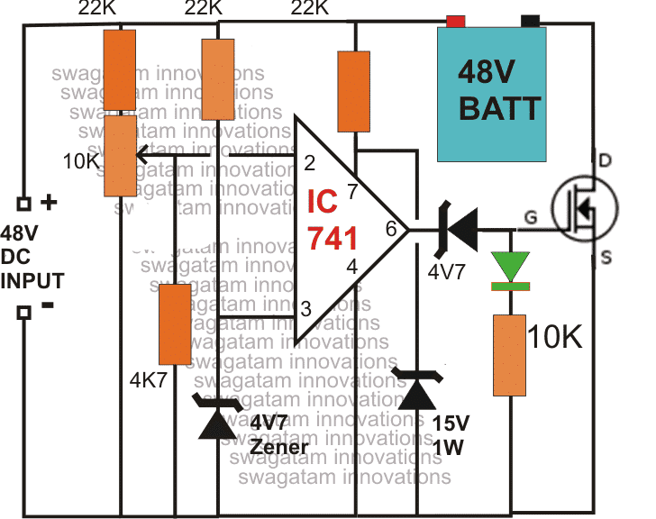
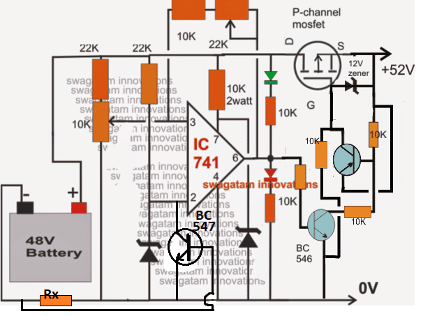
As shown in the circuit diagram, the main element in the circuit is the opamp IC 741, which has been arranged as a comparator.
Pin#3 which is the inverting input of the IC is referenced with a fixed voltage of 4.7V through the respective zener/resistor network.
The other input is applied with the sensing voltage which is actually the voltage merged from the supply and the from the battery, in other words the charging voltage which is applied to the battery for charging.
The resistor network at pin#2 along with the preset forms a voltage divider network which is initially adjusted such that the voltage at this pin stays below the voltage level at pin3, which is the reference voltage set at 4.7v by the zener diode.
The preset is set in such a way that the voltage at pin#2 rises above the 4.7 mark as soon as the battery voltage rises above 50V or the fill charge threshold level of the battery.
The moment this happens, the output of the opamp goes low switching OFF the mosfet, and cutting off the voltage to the battery.
Initially as ling as the battery voltage and the over all voltage from the 48V supply remains below the full charge threshold level of the battery, the output of the opamp stays high and the mosfet us kept switched ON.
This allows the voltage to the battery for charging, until the above explained threshold is reached which automatically inhibits the battery from further charging.
The mosfet can be selected as per the AH rating of the battery.
UPDATE: For converting this into a Solar version you can read this article
1) Using Mosfet Cut Of

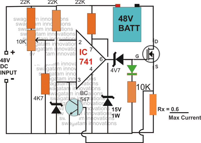
2) Current Controlled Version of the above Design
NOTE: The above diagrams mistakenly shows 48V as the input, the correct value is 56V. Because the full charge level of a 48 V battery is around 56/57 V.
NOTE: You will have to connect the battery first and then switch ON the input supply, otherwise the mosfet will fail to initiate for the charging process. Make sure the green LED remains illuminated after power switch ON, this will confirm the charging status of the battery.
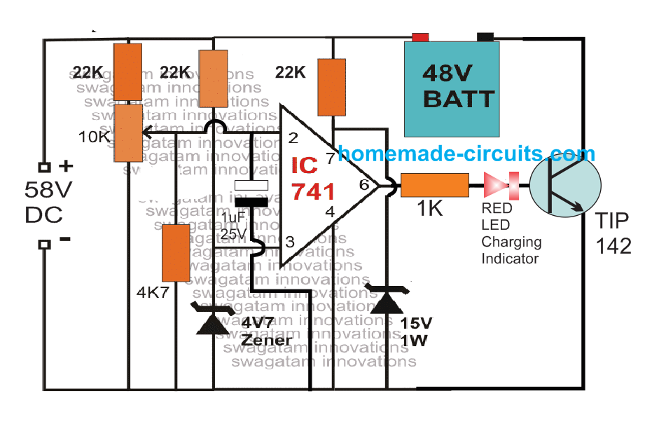
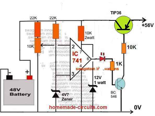
The above design can be also built using a TIP142 and a red led charging indicator.
Simple 48 V 100 Ah charger Circuit using OP Amp and TIP142
3) Making a Fully Automatic Version
The above circuit can be upgraded into an over charge cut off, as well as low charge restoring battery charger system, for charging 48V batteries.
The modifications enables the circuit to switch OFF the battery charging process at the set over charge threshold and restore back the process when the battery voltage falls below the low threshold value.
The 10k preset must be adjusted to set the full charge level while the 22k preset for detecting the lower threshold of the battery.
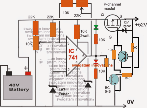
NOTE: In the above two circuits, please connect the RED LED in series with the BC546 base. This will prevent the op amp offset voltage from reaching the BC546 base and false triggering.
Simplifying the Design
The above design can be further simplified as shown in the following image. Notice that the input pins of the op amp are swapped in this design, which allowed the elimination of the extra PNP BJT from the circuit.
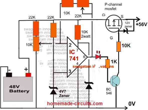
The above circuit can be also built using PNP BJT instead of a MOSFET, as shown below:
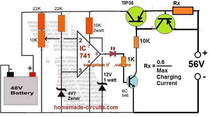
You can also add an current control feature to the above circuit, as shown in the following diagram:
How to Set up the above Circuit:
For setting up procedure, the sample power supply should be connected across the points where the battery is connected, the mosfet does not require any attention initially. DO NOT connect the battery while carrying out this procedure.
Also keep the 22k preset link disconnected initially.
Apply the higher threshold level across the above mentioned points and adjust the 10K preset such that the RED LED just switches ON. Seal the adjusted preset with some glue.
Now reconnect the 22k preset link back into position.
Next, reduce the sample voltage to the lower threshold value and adjust the 22k preset such that now the green LED just lights up, while switching OFF the RED LED.
If you find no response from the circuit try using a 100K preset instead of the 22k preset.
Seal the adjusted preset as above.
The setting up of the circuit is over and done.
Please note that during actual operations, the above circuit will remain functional only as long as a battery stays connected at the shown points, without a battery the circuit will not detect or respond.
Feedback from Mr. Rohit
I have a 50-52v solar panel setup which is charging a 48v 78ah battery. What I want is when my battery is fully charged that is it reaches to 54v the battery charging stops and the supply which is coming from the solar panels is directed to another port from which we can charge any other device connected to the port. This charging should only continue till the battery is above 48v. Once it reaches 48v the battery again starts charging on solar panels and the supply to the other port is stopped.
Hoping you will reply soon.
My Response to the above Circuit Request
You can try the last circuit from the following artcilehttps://www.homemade-circuits.
Regards
hi swag,
i need a battery cut off circuit for lithium charger 60v 3amps ( high cut off at 71vdc could have a lowcut off ) as the smps based provided fails, so i want to build with a transformer based ( necassary rectifier / capacitor) , which above circuit should i use and modification …. thank you.
Hi John,
I would recommend the last circuit, which looks most suitable for your application, because it is a CC, CV controlled design.
Make sure to reduce the base resistor of the TIP36 accordingly.
Formula is
R = (70 – 1) * hFE / 1.5
Assuming TIP36 hFE to be 20, we get
R = 69 * 20 / 1.5 = 920 Ohms or a 1k will do, power can be 1 watt
hi i wrote to you just some time , after seeing the comments, assaid before i need 72v 3 amps transformer based high / low charger , relay based, could you sugest the necassary modification.
Hi John,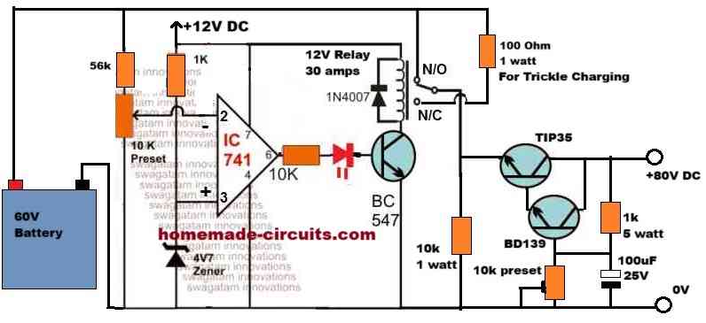
you can try the following circuit, let me know if you have any issues with the implementations:
" rel="ugc">
thank you for answer me because i have wind turbine output 48 volt and battery 24 volt
In that case you will need to first the regulate the 48V DC to 28V DC and apply this 28V to the above circuits, for charging your 24V battery with auto cut-off….
hi sir please i can i used this charging for 24volt
thank you
Hi jhjh, you can certainly use the circuit to charge a 24V battery also.
I would recommend the last two circuit designs….
Hi
can you inform me please, what kind of power supply will need for this 48v charger?
a simple 220 to 48v transformer, after rectifier bringe will give approximately 46v but after the electrolytic capacitor the voltage goes to 65vdc .
will need to put a stabilization circuit in the 56vdc? And if so, do you have a diagram of it?
thank you
Hi, you will need a 56V DC for charging a 48V battery.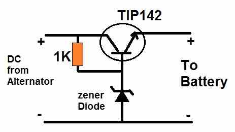
You can use a simple emitter follower stabilizer for reducing he 65V to 56V, as shown below:
" rel="ugc">
For the zener diode you can use a 56V 1 watt zener diode.
hi sir i am student doing my final year engineering and we are makeing hybrif charging station for 48 v 15-20 A charger can you pls help us to making the charger circuit
Hi Hemanth, Please provide detailed specifications of your requirement, if possible I will try to solve it for you!
sir can i use this circuit for 48v 78 AH lithium ion batteries
Hi Aravind,
Yes you use the circuit for charging your 48v 78 AH lithium ion batteries, just make sure to upgrade the relay, MOSFET or the BJT to handle upto 70 amp current.
Can you bypass all the circuitry and take the wires from 48v batteries to a cut off switch to the motor,and if so how,.And if not,can you wire any other way leaving out all the lights,indicator,etc etc wires,and if so how.
I did not quite understand your exact requirement, if possible please explain it in details.
hello Sir, I want a 48 volt LIFEPO 4 Battery charger with over charge cut off, can you provide me the circuit diagram, (if possible a fast charging recommendation I need) then I shall be grateful to you, thank you
Hi Bibhuti,
You can try the last circuit from the above article. The input charging current will determine how fast the battery can be charged. Make sure not to exceed it above 75% of the battery Ah value. The resistor Rx value can be set appropriately to adjust the maximum current to the battery.
Thank you Sir, for your quick response on my request,
Yu are welcome Bibhuti!
Hai sir i am sreenivas d, i have small doughs sir 300w inverter 12v dc to 220v ac, incase same inverter ckt, we can reduce turns primary side 12v to 75v what happened sir pls explain to me. can increase. will increase current primary.
Hi Sreenivasulu, It will change the output voltage range of the transformer. You can use the following formula to calculate it:
Vsec / Vprim = Tsec / Tprim.
In this equation, Vsec represents the secondary voltage, Vprim denotes the primary voltage, Tsec is the number of secondary turns, and Tprim represents the number of primary turns.
WILL THESE CKT ASLO WORK AS REVERSE BATTERYPROTECTION FOR P-CHANNEL MOSFET SIMPLIFIED CIRCUIT
For reverse battery protection you can add a diode in series with the drain of the MOSFET
Hello sir, thank you for the very nice circuits and all your follow up help. My question is that I want to build a charging circuit for my 12v (3S1P) lithium ion cell pack. It should have the over charge cut off as in your circuits but also an over discharge cut off for when using the pack. Your insight is appreciated.
And also what can you recommend about cell balancing as I’ve heard it can be important in such battery packs.
Thank you so much Neddan, I can provide you with an auto cut-off and auto restore charger circuit but it won’t have a cell balancing facility in it. I do not have a cell balancing circuit with me yet.
You can try the last circuit or the second last circuit from this article:
https://www.homemade-circuits.com/opamp-low-high-battery-charger/
Thank you very much, I will try out the circuit as for now I only need to use and charge.. balancing can come later on as I improve the circuit.
Sure, no problem. All the best to you.
so i have been doing this project and i wanted to ask is there any other replacement for the ic741
Which op amp is available in your area? You can use that op amp.
OPA548T is what i have available the rest are not rated for 48v
48V op amp is not required, you can use any 12V op amp. The 48V supply is appropriately reduced to 12V by the various resistor networks in the circuit.
I am also a 2nd year electronics student do and the drone is for my project i have the made a schematic system and I just need to add the charger system to it
Sure, you can use the last or the second last circuit from the above article for your application.
I have hybrid drone system and now I am trying to charge the batteries whiles in flight and I wanted to know if this automatic 48v battery charger and cutoff schematic is applicable because it is similar to what I need.
If your battery is a 48V battery then definitely this circuit can be used for your purpose.
I would recommend you this circuit:
" rel="ugc">
thank you very much
Hi my name is Ricky I have a blicks electric bike blix and it’s a 48 volt it’s a l i o n battery and I want to make a homemade battery charger for it but I am not electrician not even close to one so can you possibly give me how I would make one out of power cords already
You will need an electronic circuit to build the charger, as explained in the above article. Without proper knowledge it can be difficult for you to proceed.
Hello dear Swagatam,
thank you so much for all the informations. i need a autoturnoff circuit for a 48v Battery that will be connected to a wind turbine ,wich circuits do you recommend me to use ?
i also have a second question if you have an idea : since i want to build a little wind turbine and the output voltage will be variating (depend on rpm ) how can i connect that to a 48v battery ? or in another way : how to keep the output voltage 48v so that the battery can be charged .
thank you verry much for your answers .
best regards
Youness
Hello Youness,
You can try the following circuit for charging your 48 V battery from a wind turbine.
To setup the circuit, feed the AC from the windmill through a 20 amp bridge rectifier across Vin/0V of the circuit, and check the voltage across the output terminals. Adjust the 10K preset until the output stabilizes to 56 V.
In the diagram the Vin wrongly shows 56 V, actually it be can any value up to 100V
" rel="ugc">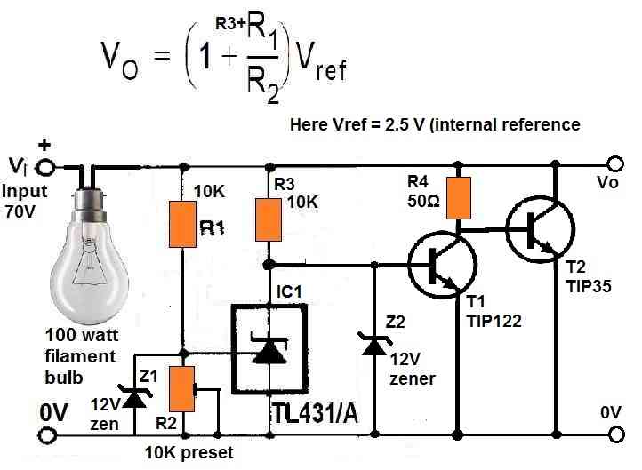
The TIP36 will withstand a maximum of 10 amps when attached with a large heatsink.
Thank you sir for your support .
i have a question . since the vertical wind turbine will not provide a stable output voltage depending on wind(for exmple between 10v and 60v ) and the Battery is a 48v Battery . will it work with this circuit that you gave me ?
thank you so much sir for your help
Youness
Hi Youness,
This type of circuit is called shunt regulator. This will keep the supply voltage at 56 V as long as the wind turbine supply is above 56 V…but if it drops below 56 V then the circuit cannot boost it up.
Hallo dear swagatam i appreciate too much. My name is Léon makinde.i’m extremely happy to hear for you.i would need your help please. Im working on a 48volt battery charger.i tested all the components they seem to be good.but the drivers input voltage is zero. Please assist me my email address is :makinde.leon@yahoo.com
Thank you Leon,
Which schematic did you use for your 48 V charger? And please elaborate a little more on “drivers input voltage is zero!
Hello Mr Swagatam,
For circuit 2 current controlled circuit. How can i control the current? As i know, i only can control the voltage from the 10k potentiometer.
Thank you,
Wan
Hello Wan,
The 2nd current controlled circuit is not a tested design so i cannot suggest about the current control feature. I would recommend you to include the current control feature at the input side, with the power supply itself.
Hello Mr Swagatam,
As i tested the current controlled circuit, it is not maintain as constant current Which is 3A as i need. I did use power supply use 3A input it gives a constant current.
The 1st circuit that i test is only for constant voltage. As we know for a battery charger it should be constant current then followed by constant voltage. What’s your comment about this?
Hello Mr.Wan,
Current will depend on the battery consumption and will keep changing as the battery reaches its full charge level.
If you have a constant 3 amp charger then there’s nothing to worry about.
If you are still worried you can use an external current controller between the charger and the power supply. You can use one of the current controller circuits explained in the following article:
2 Best Current Limiter Circuits Explained
We use AC source and convert it using rectifier. Is it possible for me to combine using mosfet cut off charger circuit and mosfet for high current applications? I use the right Rx= 0.6/3 = 0.2Ohm but the current is not constant or maintain. I have tried use the 1st circuit, the characteristics shows for output current is decreasing. Not as we know for their constant current at first then change to constant voltage.
Current will depend on the battery consumption and will keep varying as the battery charges. The constant current can only ensure that the current does not increase above the set limit.
For example if the set limit of the current control circuit is 3 amps then it will ensure the current never inceases beyond 3 amps to the battery. But the current can be lower if the battery consumes lower current, which solely depends on the battery.
Output current surely decrease as the battery reaches full charge level and finally the current will become zero.
Voltage will be constant after the battery is fully charged only if you use a constant voltage regulator power supply.
You can try the following concept for a constant current with auto cut off:
" rel="ugc">
As I know, after the constant current characteristics, the output current will decrease after the threshold voltage is achieved. Then the battery will charge with a constant voltage. Finally the current will become zero. So by using the concept that you suggest, is it still can be charged with constant current and constant voltage mode with auto cut off system? thank you for your help.
That is correct but that is decided by the battery not by the power supply. The power supply can only limit (restrict) the max voltage and max current to a certain fixed level as determined by the regulator circuit. For example a 12V constant voltage will limit the output volt to 12V and a 5 amp constant current power supply will limit the current to 5 amps. The amount of current and voltage to consumed is solely decided by the battery while charging. The power supply can only ensure that the battery does not pull anything beyond a certain fixed limit so that it remains safe from over voltage or over current..
The circuit suggested by me will restrict the output voltage to a fixed max level as set by the 10K preset and will not allow the voltage to the battery above this limit. Similarly the maximum current will be set by the RX resistor, which will never exceed beyond that limit.
I have tried this circuit, this question is how to set the cut off? I am using the variable resistor to set but doesn’t show any changes. I connected the input and battery, the Led does not light up. I use Rx= 0.2Ohm since i want 3A current. If I connect it, is it charge? The input voltage is set at 56V there is no current flow. Thank you fo your help Mr Swagatam.
Hello Wan,
The setting up procedure for the following circuit is as given below:
" rel="ugc">
1) Keep the wiper of the 10K preset towards ground.
2) Feed 56 V from the BATTERY SIDE, remember from the battrety side, not from the transistor side….but do not connect any battery during this testing period.
3) You will find the LED glowing brightly.
4) Now, slowly adjust the 10K preset until the LED just shuts off.
5) That’s all the setup is complete.
6) Now, remove the power supply and connect a discharged battery.
7) You will find the red LED illuminating.
8) Now connect the 56V from the transistor side for initiating the charging process.
9) Once the battery is charged to 56V the red LED will shut off indicating that the battery is fully charged.
Hello Mr Swagatam
I have followed all the procedures one by one that you have mentioned but I failed to charge the battery.
Firstly, I have connected 56V supply from the battery side to vary the cut-off voltage. But the LED does not light up and no current flows. As you could see the first circuit you used 4.7V zener diode at pin 6 while this circuit is connected to the led directly. Both transistor used at current constant side is TIP36 right? Instead of using 12V zener diode, may i use 15V zener diode? Why do we feed the input reversely with the first circuit? Is this the way to get the constant current at first and then constant voltage?
Thank you Mr Swagatam for your help. I really appreciate it.
Hello Wan,
The following circuit is a simple op amp comparator circuit and should work 100% without fail, and setting up is also simple.
" rel="ugc">
If the red is not lighting up in your circuit while adjusting the preset then definitely something’s wrong with the op amp or the connections.
I think your 15V zener might be causing the problem….please try with a 4.7V zener or 6V zener and check the response.
The main PNP transistor on right side can be TIP36 but the current controller PNP transistor can be any small PNP transistor but 100 V rated, such as BD140.
We feed the voltage from the reverse because we want to adjust the preset at 56V. If we feed the voltage from the transistor side then the TIP36 will create problems and not allow correct setting up.
Constant voltage is decided by the automatic 56V op amp cut off which means the voltage can never go beyond 56V, and this is constant voltage.
Constant current is determined by the two PNP transistors and the RX resistor which will never allow the current to go beyond the set value depending on the Rx value..
Hi Mr Swagatam,
Thank you for the previous response.
I have troubleshoot the circuit looks like my IC741 is burned so i have changed it. I have varied the trimmer pot to the certain voltage to be cut off.
Then I connect the Battery to the battery input side, next i connect the power supply to the power supply side then the TIP36 on the left side is on fire/burned. Do you know why this happen?
Is both transistor you used is the same concept with darlington pair?
Hi Wan,
TIP36’s voltage rating is 100V and current is 25 amps so it should not burn at 56V 3 amps or 5 amps.
The two transistors are not connected in Darlington mode, they are in current limiter mode.
How much value did you select for RX?
Did you connect the transistor pins correctly?
If you are having problems with transistors then you should use a relay instead. But relay will require an external 12V source to operate.
Try with the following circuit first:
" rel="ugc">
If you succeed then try the other one with current limit.
Hi Wan, also please replace BC546 with BD139 because BC546 can handle only upto 65 V which is very near 56V….we want a higher margin of at least 20 V, so please if possible replace BC546 with BD139
Thank you Mr Swagatam for you reply.
I use Rx 0.2 since I need 3A.
Yes, the transistor pin is connected correctly.
There is a voltage difference before I vary the trimmer pot. After I vary there is no voltage difference.
Why did you use 4.7V and 12V zener diode as reference?
The circuit should be charging the battery without any problem with those suggested components right?
Thank you for your suggestion on the Transistor BC546 used.
Hi Wan,
The 10K preset uses the 4.7V as a reference and cuts off the output as soon as the preset wiper voltage exceeds 4.7V, corresponding to battery 56 V.
If you use 5.6V or 6V or 9V zener then the 10K preset will need to be adjusted accordingly so that it feeds the adjusted battery voltage to the opamp pin#2 which compares it with the reference voltage and cuts off the output at the corresponding 56V.
In this way the op amp uses the preset adjustment to compare with the reference level so that when the battery voltage reaches 56V, it cuts off the output.
Basically when the pin#2 of the op amp increases above the 4.7V reference then the output cuts off. This is adjusted by the 10K preset to happen at a level that corresponds to 56V for the battery.
The maximum range of the 10K preset is between 3V and 17V. So the reference zener voltage must be between these ranges.
The 12V zener is for providing 12V regulated DC supply for the op amp which is a reasonable value for the op amp Vcc
Thank you Mr Swagatam for your explanation.
The circuit should work perfectly right?
Where did you get the 0.6 Reference voltage? For example if we use LM317 the voltage reference is 1.26V so to get the current 1.26V/Current.
I check my Rx is burned so i have change a new one then the circuit is charging the battery.
I want to use Rx=0.2 since i want 3A current. The charging current measured should be 3A after connected to the battery then when it reached the threshold voltage it will decrease.
The temperature at TIP36 increase to 80degree celcius with current 0.8A only and both keep increasing. Is that noral for TIP36?
Hi Wan,
The 0.6 is the optimal base/emitter switch ON voltage level of any BJT. The current limiting transistor associated with TIP36 will switch ON when the current exceeds 3 amp and creates a voltage drop of 0.6V across Rx.
The power of Rx will be
Power = 0.6 x 3 = 1.8 watts, so you can use a 2 watt or 5 watt resistor for Rx.
You must use a large heatsink for TIP36.
And preferably in place of BC546, please use BD139
Hi Mr Swagatam,
I need 3A current, hence 0.6/3=0.2 ohm. I have tested with 0.2ohm, and after an hour it gives me 0.723A constant current. The current increase slowly after 15 mins it started to constant at 0.723A. After 2 hours current start to drop 0.717A but the battery capacity is not at full yet and not achieve it threshold voltage to turn into constant voltage.
I have changed to a bigger heatsink the temperature of TIP36 is maintained around 59 degrees Celcius.
Soon as I receive BD139, I’ll change with BC546.
Thanks for the update Wan,
As I explained you before 3 amp constant current means the current cannot increase above 3 amp. 3 amp is the maximum limit set by the charger circuit.
But now it depends on the battery how much it wants to consume.
3 amp limit does NOT mean the battery will consume 3 amps, NO.
Battery can consume 500 mA, 1 amp, 2 amp, 2.5 amps or anything below 3 amp…. this will depend on the battery.
Battery will reach full charge when 56V is reached and then the op amp will cut off…LED will shut off.
Yes, Mr. Swagatam. So I need to use a smaller resistor to achieve a higher current?
I have tried Rx 1Ohm, thus I got 0.519A. The higher resistance I used, the smaller the charging current.
Do you have any idea how to produce a 3A charging current other than using smaller resistance?
Hi Wan, yes use smaller resistance to achieve higher current and vice versa.
the method shown in the diagram is the only correct way to restrict current.
This current value should be 1/10th of the Ah rating of the battery, if the battery is a lead acid battery.
Hi Mr Swagatam,
What is the use of 10k between TIP36 and BC546. As I changed it to a lower resistor the current increased.
Hi Wan,
the 10K decides and base current for the TIP36 and it also decides how much current the TIP36 can deliver to the battery.
This 10K looks too big actually.
You can reduce it to 470 ohms or 100 ohms and check the results.
I think there is no current flow on the TIP36 for the input side since no heat on the heatsink. The temperature on it is maintained 22 degree celcius. While the other TIP36 that connect to BC546 increase in temperature to 80 degree celcius.
You can decrease the TIP36 base resistor to 470 ohms and check the results.
Hi Mr Swagatam,
I have reduced the resistor for base current TIP36 all looking good.
However, I changed BJT to MOSFET(IRF9530) and it produces better current measurement. Are there any difference of using BJT and MOSFET as i know both can control current and MOSFET for high performance.
By using MOSFET the temperature of it also high so i need to add a fan for better heat dissipation. Do you have any idea to reduce the temperature, what FET should use.
Hi Wan,
MOSFET gates cannot tolerate voltages above 20V, so if you are using a mosfet then make sure to connect a zener diode across its gate and source pin.
The zener diode can be a 12V zener diode with cathode going to the source pin and anode to gate pin.
Also replace the gate resistor with a 10K resistor otherwise the zener will burn.
IRF9530 is a good mosfet, but i think it might be already burned due to the absence of the zener diode.
Hi Mr Swagatam.
TIP36C is good in testing with the temperature of 80-degree celsius at current 2.96A.
However the current keep decreasing and is not constant.
As I know this circuit is only for limiting the current below the maximum charging current that we need.
Do you know how to make it a constant current and constant voltage?
Hi Wan,
I think you are not understanding the working concept.
Constant current means the battery cannot consume current beyond a certain limit. For example if a constant current 5 amp is selected then the battery cannot pull beyond this 5 amp current limit.
But if the battery consumes 4 amps or 3 amp then it can do, we cannot force it to consume 5 amps.
Initially the battery current consumption will be high, but as the battery charges its consumption will keep decreasing until it becomes zero.
For voltage it is the opposite.
Initially the voltage will drop to the battery level, then as the battery charges the voltage will keep increasing until the battery is fully charged.
Is constant current means the current charging remain constant continously until the constant voltage mode is achieved? It also limit from the overcurrent. The best charging method for LI Ion batttery is constant current and constant voltage mode. Firstly the battery is charge with constant current mode continously until almost full it turns to constant voltage mode gradually decrease to provide safety for the battery.
Constant current means current limiting, that’s all. It is the battery which decides how much current it can draw below the current limit.
In constant voltage the battery cannot charge after the full charge level or at the voltage which has been fixed by the power supply, that is why it becomes constant voltage after the full charge level.
For example if the fixed voltage level is 14V, then when the battery voltage reaches 14V it cannot charge anymore so the voltage becomes constant.
Constant voltage and constant current are maximum limits which the power supply allots the battery. Beyond these limits the battery cannot draw the current and voltage.
Constant current constant voltage does not mean that the power will keep varying and FORCING the current and voltage to the battery….never.
It is the battery (load) that decides how much current and voltage it needs to take below the specified limits.
I hope you have understood now.
Thank you for your explanation Mr Swagatam. I get what you said now. Hence the power supply itself we need to control to the maximum limits which allow to the battery.
I need to create the charger for a 48V,8Ah battery. This circuit is the best for the charging circuit as you suggest?
You are welcome Wan, I am glad yu have understood the concept now.
Yes, the suggested circuit is the easiest, safest and the best for charging your battery.
" rel="ugc">
If your 8 Ah battery is a lead acid battery then make sure to limit the current to 1 amp and set the full charge cut off voltage at 56 V.
For lithium-ion battery the charging current can be around 4 amps
If you don’t want to use the current limiting transistor stage, in that case you can use a power supply which is rated at 1 amp for lead acid, and 4 amps for lithium-ion..
My battery is Lithium-ion. I would like to use the current limiting transistor. Currently, I’m still finding for a suitable resistor for the 3 Amps current limit. When i calculate 0.6/3= 0.2ohm and the current gives only 1.8A with the 0% battery at 44volt. I use 10W resistor for better performance and heat transfer.
May i know your test on this circuit how much current you limit ,does the current limit as you want constant below the limit current, the Rx resistor that you use and does it works for long term.
Thank you very much Mr Swagatam for your help.
Hello Wan,
I did not use a current limiting stage in my circuit instead I used a transformer rated at the specified amount of current. I needed 1 amps, so I used 1 amp transformer for the power supply.
However, a transistor circuit may not be too accurate with its output, so you can try reducing the 0.2 ohm to 0.1 ohm and check whether it delivers a higher current or not.
Also make sure that your input power supply is rated at 3 amp or slightly above 3 amps.
If Rx is a wire wound type resistor then it will work permanently.
The supply I used is AC supply and convert to DC using a bridge rectifier and connect to the circuit that you suggest. Thus, i can’t get the specific Amps for it.
Do you have any suggestions for it?
I highly appreciate your suggestions and explanations.
How did you drop the AC supply voltage to 56V? I strongly recommend using a transformer. You can use a 48V/3amp transformer or a 24-0-0-24V 3 amp transformer and rectify it using a single diode and filter the DC with a 1000uF/100V capacitor. With a 3 amp transformer you won’t require a current limit.
Actually for a 48V lead acid battery the max charging voltage will be 56V, but for Lithium-ion it will be slightly different but will be critical.
I have tested one of the chargers in the market. The voltage increase from 44V(0%) to 55V(100%). The current remains constant at 2.85A at 44V until 54V and starts to decrease after 54V gradually until 55V when the battery has full.
Do you know why the current is constant?
Maybe 2.85 Amp is the maximum current the battery is consuming and the charger is able to supply this much current to the battery. In our previous circuit the transistor is not able to supply 3 amps, maybe due to high base resistor base. You can reduce the base resistor and try again.
…or you can replace TIP36 with TIP147 which is a Darlington transistor with high gain and high current output.
The TIP36C i used is 25A Ic. TIP147 is 10A Ic. I have searched in the online store TIP36C is the highest Collector current.
I used a AC-DC 230Vac-48Vdc supply with 2.08A. The current is not achieve at the maximum rated current and not maintain when charging the battery. I have tested 3 Batteries. Trial and error the resistor at base and Rx. The suitable base resistor to use is around 2-2.5kohm.
Since your maximum current requirement is below 3 amp so 10 amp transistor is quite sufficient, no need of a 25 amp transistor.
I am suggesting TIP147 because it is a Darlington transistor and will be able to transfer current with maximum efficiency.
Also, since your input current is limited to 2.08 amps then no need of the current limiting transistor stage. You can remove it and use 1K resistor for the base resistor of TIP36
Thank you for your suggestion on using TIP147. I will try to do it as well.
I have removed the current limiting stage. My supply is fixed at 48V and 2.08A. I connect with 3k for base resistor TIP36. The initial current measured is 2.23A. The current is decreasing to 1.98 after 15 minutes of charging. The battery I used is Lithium Ion 48V 10Ah.
According to the formula of the transistor base resistor:
Base resistor = (supply voltage – 0.7)hFE / Current
= (56 – 0.7)15 / 3
= 276 ohms
So the base resistor must be rated at around 276 ohms, wattage can be around 2 watts to 5 watts.
For 48V battery the charging supply must be around 55V to 56V.
If you use a TIP147 then the base resistor can be anywhere between 1K and 10K due to the high hFE of the transistor.
Hi Mr Swagatam,
I have used TIP147 as you suggested. I change the base resistor to 1k and the current reading is 2.35A. If I reduce the smaller resistor the current will increase. However, the current is not constant. I have used the supply 56V 2.08A.
https://www.homemade-circuits.com/universal-high-watt-led-current-limiter/
From the above, I can see the graph voltage vs current where the current is constant until the cut off then it gradually decreases.
I have tried using LM317 it is constant but only at a low current.
Hi Wan,
For TIP147, the base resistor should not be decreaesd below 1K, it will not help because 1K is enough to turn ON the transistors with high gain.
As I mentioned before, current consumption will depend on your power supply and the battery consumption, the transistor TIP147 or TIP36 are just a kind of ON/OFF switches, they can only supply the full available current to the battery and then it will depend on battery how much it wants to consume. When the battery is discharged it will consume high current, as it gets charged, the consumption will decrease.
LM317 is also a current limiter only, and will restrict the current to a certain limit depending on the resistor value.
Hello Mr Swagatam,
I would like to create a 48V with 10 Amp battery charger circuit. Is circuit number 1 is suitable for it? I notice that I need to change the mosfet that suit with 48V,10A. What about other components?
Thank you,
Wan
Hello Wan,
The first circuit is fine, but the last circuit is the best one. You can try the last design. You can replace the TIP36 with MJ11033 transistor, and also replace the 22K at pin#3 of the opamp with 10K 1/4 watt.
The transistor datasheet can be seen in the following article:
https://www.homemade-circuits.com/50-amp-transistor-mj11032-mj11033-datasheet-pinout/
Hello Mr Swgatham,
I am planning to use the last CKT which you have posted in this page. My application is for charging the 48V 36AH lithium ion battery pack. Following is my Question.
Is this CKT already tested with actual load? I meant charging the actual battery pack and testing the over charge cut off and under charge switching ? Just to know if there are any observations that to be taken care.
Vijay
Hello Vijay,
The first, third and the last circuits are tested, rest are not tested but I am sure all will work. However, you can build, test and troubleshoot these circuits successfully only if you understand the working and the setting up procedures perfectly.
I would recommend you building the last circuit with an auto cut off feature, however it does not have an auto recharging feature and will not restart automatically once the battery has reached a low state. Nevertheless, this feature can be easily added through a simple feedback network.
Hi Swagatham,
Thanks for the confirmation. I will consider your recommendation. But I am just thinking that, when there is Battery management system integrated with the battery pack, does the battery charger also needs the cut off feature? As BMS normally protects the battery in all aspects, whether this extra protection is required? anyways the protection circuit using opamp is not expensive to build….
Vijay
Hi Vijay,
A battery management does not need an auto cut off because a BMS will have all these features included in it. Yes it is normally designed to protect the battery from all the unsafe aspects of charging.
Hi Swagatham,
Thanks for your feedback.!
Vijay
You are welcome Vijay!
Hi sir,
my motorbike’s battery is 72V (20S, 3.6×20 Li-ion in series), pls let me know which components i have to change to new value, pls kindly advise.
Hi Virapong,
You can try the last circuit from the above article. Replace BC546 with BD241C
Make sure to feed 84 V DC to the emitter of TIP36.
Thanks for your so kind advise, i also building 3 LEDs battery indicator from your post below:
https://www.homemade-circuits.com/?s=3+led+battery+indicator
for my 72V battery, pls let me know of what zener diode value, ZD1-3, R? of red,green,yellow LED, and which NPN transistor# to replace BC549? for my 72V battery,
thank you very much in advance.
ZD2, ZD3 zeners combined can be around 82 V, R2 can be 4K7 1 watt
ZD3 can be 75V.
R1 and R4 can be 4k7 also, but may need some experimentation.
Both the transistors should be 100 V rated (across collector/emitter)
Thanks Sir,
i had followed your advise, and tried your circuit with circuit wizard free software as below link:
https://drive.google.com/drive/folders/1IwUWKo0iokZyZorTf6aLDv4pROwCWH5b?usp=sharing
https://drive.google.com/file/d/1B6RqzOt4zXhgb2EaXTuYvzvxNQYlyrfY/view?usp=sharing
https://drive.google.com/file/d/134I7rcKkjzTLW9wxrS2MFvG2o880ZQV2/view?usp=sharing
and simulate it, but seems not working right, pls let me know of what went wrong, THANKS, what transistor# should i use?
Virapong,
I never use softwares to simulate my circuits, because softwares can be wrong. I always test them practically to check the results. But before this I make sure I understand the working of the circuit so that I can troubleshoot it without difficulty.
So I would recommend you to first understand the circuit functioning and then test it by practically building it by soldering the parts on a general purpose PCB.
Once you understand the functioning of each of the parts in the schematic you will not have to depend on any softwares.
Thanks Sir, i had followed your advise to had ZD2+ZD1=39+43=82V, R1=R2=R4=4K7/1W, ZD3=75V, and Q1=Q2=TIP122, and experiment with different voltage level below:
72Vdc, only yellow LED ‘on’, green and red LED had reversed voltage>5v and could be damaged. (but we need only green LED to be ‘ON’)
84Vdc, all LED, green, yellow, and red are all ‘ON’, (but we need only red LED to be ‘ON’)
60Vdc, yellow LED ‘on’, green and red LED had reversed voltage of -14.6v and damaged.
pls advise how to prevent LED reverse voltage so that i can do experiment again, should i change to another transistor?, thanks for your kind supports.
Virapong,
The LEDs can never get damaged due to the presence of 4k7 resistors. So do not worry about any reverse voltage.
When red LED is ON, the green and yellow should be switched OFF, because the red led’s forward voltage is minimum than yellow and green. Similarly when green is ON, yellow will be off.
I will suggest you to first test the circuit at 12V using the same components as given in the diagram and check whether the circuit works in 12V or not.
Once confirmed then we can adjust the circuit for 80 V.
For further discussions you can comment under this post:
https://www.homemade-circuits.com/3-led-battery-level-indicator-circuit/
Thanks Sir, for your very good advise, i had tested your 12V circuit with 12Vdc input, turn out that both green and yellow are ‘on’, then i add 1.4k resistor series with yellow LED in order to turn-off yellow LED, and when i apply 14.5Vdc the red, and green are ‘ON’, and i have to put another 3K resistor in series with green LED to turn-off green LED, but now when go back to 12Vdc, both green and yellow LED are ‘ON’ together again, pls kindly advise me of how to solve this ‘2 LED lighting at the same time’ problem.
Hi Virapong,
To ensure the LEDs do not light up together we have to use LEDs with different forward voltage specifications. I think nowadays all white LEDs have identical forward voltage specification which is creating this problem.
Earlier we used to have RED LED with just 1.5 V forward voltage, so when another LED with 3V forward voltage specification was connected parallel to the red LED, only the red LED could light up and the other LED would remain shut off.
But today maybe all LEDs have the same 3.3 V forward voltage spec which causes them to light up together when connected in parallel.
So this problem cannot be solved.
You may have to try some other concept such as these:
https://www.homemade-circuits.com/low-battery-indicator-circuit-using-two/
https://www.homemade-circuits.com/battery-full-charge-indicator-circuit/
i have a 48v 2.5 amp charger model lyd-150w-ch my voltage reg is done and there is no numbers on it. what kind of reg should i use. i have tons of them but wich one would work for this
Which type of 48V regulators do you have with you?? If you could specify the working I might help you to select one of them.
Hello sir how are you ?
sir as you know i have phosphate battery 12s 12ah 38.4v i tried this circuit but facing problems like i said before while voltage reach near threshold value circuit out cut-off flactuating. I tried adding diodes, capacitor as you said but no luck can we replace mosfet with relay ?
But main 2nd problem is when my battery bms turn off battery bcz of low voltage this circuit doesn’t detect anymore as a result not work for 0 volt (0 volt bcz bms turn off output) batteries
i applied 39.9 volt as a input..
Sir can you suggest me how to add relay in this circuit so when i connect charger to this bms protected battery which have 0 volt when battery reach to 39.9v (80%) just cut-off that’s what i want sorry but please help me i tried lot’s of way to come up wid this problem but no success
Hello Happie,
I have tested the first concept with a 3.7 V battery and it never fluctuated for me. Once the battery is cut off the charging is cut off permanently. I am not sure why it is fluctuating in your case. You can try connecting a 100uF/100V across the gate/source of the mosfet.
I would recommend using a BJT such as TIP142 instead of a mosfet, because a mosfet can be a duplicate in quality but BJTs are mostly original and reliable.
Do not use BMS while using the above circuits, because I have designed the above circuits to work with a direct battery only, not through any external controller.
The fluctuations can happen in the last 3 circuits, which can be controlled by adding a feedback resistor across pin#2 and pin#6 of the IC.
A relay cannot be used because the relay coil will need to be rated at 42V, which is difficult to find.
I would recommend you to try the last circuit, it is very reliable, but it will fluctuate after cut off because after cut off the battery voltage will tend to drop rapidly which will trigger the op amp to switch ON the transistors again and initiate the charging supply.
But this fluctuation is not bad because it ensures that the battery remains always topped up at the full charge level.
Remember, for any circuit you should first thoroughly understand its working, only then you will be able to built it successfully and troubleshoot it without depending on me.
Hello sir i tried your 1st MOSFET cut-off circuit with lm358 and ca3140 op-amp but i have some doubts in my mind i don’t know how to set-up this circuit can you explain clearly, i also measured voltage on pin 3 it’s 5.1v bcz i used 5.1 zener when i try to vary volatge using potentiometer when voltage reach at same 5.1 in pin 2 as pin 3 red led turns on and off rapidly and output fluctuate is this normal ? i used single supply input for op-amp is that causing issue ?
bcz i have only single supply rail thanks
Hello Happie,
In the first diagram, you will have to setup the preset in the following manner:
While doing the following setting up do not connect any battery.
1) Initially keep the slider of the preset fully towards the ground line.
2) Apply the full charge voltage of 56V from the left side. You will find the LED switching ON.
3) Now slowly adjust the preset until the LED just shuts off.
That’s all, your circuit set up is complete now.
When an actual battery is charged the circuit will cut off the supply to the battery at 56 V.
During actual charging remember to the connect the battery first and then apply the 56V.
Actually sir i ordered new battery for my e bike 36v 12ah phosphate battery.
i don’t want to full charge my battery I just want to charge it upto 80% can you suggest best cut-off voltage 42 or 43 ?
and second thing i set up circuit as you said on 42v now after led fully turns off why some voltage present like 500mv present on gate pin is this normal or do ineed to add diode to discharge gate to ground ?
For a 36V battery the 80% charging limit could be at 42 V. So 42 V is a good level to ensure that the battery is never over charged.
Normally there can be leakage offset voltage of around 2 V at pin#6 of IC 741 even after the cut off, that is why I have included a zener diode to block this 2 V. So according to me there should be 0 V across the gate and source of the mosfet after the cut off. Try connecting a 1uF/25V or 10uF/25V capacitor across the gate/source and see if the 0.5V still exists or not. Nevertheless the 0.5V will not create any problems, so you can ignore that
Now everything is super clear for me sorry for asking too much of questions ????
And thank you so much now i only need to add current limit to 2 amps which resistor should i use ?
actually i didn’t understand resistance calculator formula like i tried 0.6÷2=0.3 what it’s mean ?
Should i use 30ohm resistor or 3ohm only ?
No problem Happie, glad it helped you.
0.3 = 0.3 ohms
However I would not recommend you to use the current control stage with the op amp as it can create complications during the charging process.
Instead you can use a current control at the input side of the power supply so that the opamp and the battery gets a current controlled supply from the input power supply.
Very informative definately I’ll add current control circuit in smps thank you..
Sure, no problem.
0.3 means 300milliohms right ?
Means 3 1ohm resistors in parallel do the job ? correct me if I’m wrong also where should i get this milliohm resistors ???? i only have 1 ohm
Yes that’s correct, you can use 3nos of 1 ohm in parallel
I have a battleborn 200 Ah (2 100Ah in parallel). A Renogy 1000 W inverter. When I plug in the 58.8 V 3 Amp quick charger to the 56V eBike battery to charge, it starts up for 4 seconds then shuts down. It repeats this 4 times and then the alarm and shut down. My wife’s 42V 2 amp charger works perfectly on her 42 V battery on the inverter.
This problem will need to be checked practically, I cannot judge the fault without checking it.
Yes sir can u lecture me here. Between an ordinary inverter (square wave) and modified sine wave inverter,which one consumes less energy or power from the battery will no noise? Thanks
Morris, it is not about whether a square wave is used or a sine wave PWM is used, it used about how much average current the mosfets are able to deliver to the transformer…that decides the overall wattage capacity of the inverter. Square wave will produce more noise than an SPWM or modified sine wave.
Morning, please how can I adapt this circuit to one of 29 volts 40ah Li ion charger. Thanks
You can use the same circuit which is shown in the above article, no need to change anything for you 29V Li-ion battery. Just make sure the input current to the circuit and the battery does not exceed 50% of your battery Ah rating.
Dear Swagatham, As usual , a very simple and practical design.
Ref : Last circuit
Going through the questions and answers below, It seems you recommend using N-Channel Mosfet instead of P-Channel as given in the circuit. Also you seem to have omitted the green led (ON – indicator).
Some confusing seems to exist regarding mosfet cutoff voltage 5+48 =53V . is that so ?
I am planing to use this (LAST) circuit with 12V 100A lead-acid battery with a 15V transformer. Regarding this , you advised to remove 22k resistors and the 15v zenner connected to pin#7 of 741 IC.
Though you mentioned about the circuit to have been modified , It still shows mosfet to be p-Channel
Can you clarify on this , If possible upload the modified circuit too (for 12V battery (max 14.5v)) .
regards
Suresh Babu
Dear Suresh,
The last diagram should be actually exactly as shown, nothing can be removed from that diagram. Instead of p-channel mosfet you can use an N-channel on the ground side line of the circuit.
I don’t remember about the modifications, since those comments were posted a long time ago.
The low voltage cut off is 44V, and the high cut off is 56V.
Dear swagatham,
Thank you for the reply.
So which circuit should I use for 12v battery?
Dear Suresh,
I am sorry I think I missed the point that you wanted to charge a 12V battery.
Yes for a 12V battery you can build the following circuit. To set up apply the circuit, do not connect a battery initially, and keep the preset wiper on the ground side, disconnect the 22k preset line. Next, from the battery side apply 14.5V from a variable power supply, the LED will be illuminated. Now adjust the preset until the LED just shuts off. Your circuit all set now. The 22k perset and 10K feedback line can be replaced with a fixed 100K resistor.
Dear Swagatham,
Thank you very much for taking time to write a detailed answer.
regards
Suresh Babu
My pleasure Suresh!
I find the 48 volt DC battery charging circuits interesting.
I have a mobility scooter that is driven by 4 – 12 volt 20 A gell cells.
I live in “The Great White North” so I’d like to feel safe to leave my (55 V ?)charger
on for long periods of time. (Weeks??)
Any suggestions?
Thank you, yes the designs can be effectively used for charging most 48 V batteries with a precise cut-off at full charge levels.
The last one is the most efficient and easy to configure.
To ensure a longer life for the batteries it is recommended to keep the full charge threshold a bit lower than the optimal mark. For a 48V battery this would be around 57 V, which will make sure that the battery is cut off at its 80% charged state, which maybe slightly less than the optimal point, nevertheless will guarantee reduced stress and a longer life for the battery.
If instead of the DC Voltage source I want to use the AC input what would be the changes then ?
AC cannot be used as the voltage source. You will have to convert it into DC through a bridge rectifier and use it.
Do you have any diagram to convert AC to DC from 220V – 57V 15 Amp using bridge rectifier.
You will need an SMPS circuit for that, as given in the following example:
https://www.homemade-circuits.com/smps-2-x-50v-350w-circuit-for-audio/
Hell Mr Swagatam, I have a 48v / 25Amp Lead Acid battery charger for a Golf Cart. The control board is burnt and I am looking for a circuit to enable me to use the existing transformer to build a smart auto-off charger.
Your guidance will be appreciated. Thanks Mark
Hello Mark, the first circuit is simple and very effective, so you can use it for charging your 48V battery, If your battery is a lead acid battery, just make sure to use a transformer with a current rating that’s 10% of the battery Ah value, and the maximum output voltage to the circuit does not exceed 60V. A bridge rectifier is not necessary, a single diode half wave rectification with a 2200uF/100V filter capacitor will be enough.
Thank you Swagatam. And this first circuit will automatically switch off once the battery is charged?
Yes, the circuit will shut off the supply to the battery automatically as soon as it reaches the set full charge level.
Please, most of your component you used are not in Nigeria.
How can you help with that sir.
Am interested in your tutorial practical lesson.
Sorry I can’t help you with the components purchase. If you have specific questions regarding electronics you can ask me here!
I am looking to build an intelligent charger for my 48v Lead acid battery Golf Cart. It has 6 x 8V 105Ah Trojan batteries.
Would really appreciate your help and guidance.
Intelligent charging will allow fast charging, but will require a 3 step charging and a temperature control circuitry, which can make the circuit unnecessarily complex…instead it is better to charge your battery with a constant voltage and low constant current for a relatively longer period of time and get the same results, in fact better results, only downside being the longer time required for the charging….
Can you recommend a circuit that would achieve this? Critical is the auto off as chargers on Golf Carts tend to get connected and forgotten 🙂
dear Swagatam, i have one doubt can i use a 400 watt scr voltage controller for ac then a rectifier circuit for making it dc after that ur circuit for making a 48 volt 6 amp charger circiuit without any tranformer
Hello Sunil, you must use an smps or transformer based voltage step down regulator, scr is not recommended.
I purchased a 48 volt batt. Charger for my e bike from Walmart online recently. They sent me the wrong one. I then ordered another and it came four days late. When I plugged it into my battery pack the red led light signaling it was charging did not work. My battery pack had been sitting for a few weeks so I knew they were week. Anyway I am a disabled navy vet and I get around on an e bike. The longer I wait around for parts the longer it takes me to get around. So I have been looking for ways to maybe make m own charger . The thing is I am not to bright in the electronics field . Thank you
You can try one of the above circuits, however, if you very new to electronics then I won’t recommend building it yourself.
Hello sir, we are designing a varible voltage charger (i.e A charger with 12V, 24V, 36V, 48V output). Please help us in designing this.
Hello Shubham, what is current range of the charger, and do you want an auto cut off?
Hola buenas noches, una consulta los valores de las resistencias de q potencia de son ?? Gracias
Hello, all resistors are 1/4 watt 5%, except Rx which is = 0.6 x Maximum current
Good night, I made the circuit work, without load it reaches 48 v but with load it gets too hot, I put a heatsink but the tip 142 burned anyway, as I saw your manual it is only 10 A I can put 3 in parallel to get 30A ? Or that it may be failing .. thank you
Thank you, and glad it is working for you. Yes the TIP142 is rated at 10 amps but practically it cannot handle more than 5 amps with a large heatsink on. 3 in parallel can tried, just make sure to mount all the 3 of them over a single common heatsink
Alternatively you can replace the transistor with a mosfet. An IRF3205 should work nicely for your application.
hi . i would like to make a variable resistor controlled shut off . i’m wonder would it be as simple as just replacing the fixed resistor on pin 7 with a variable resistor . thank you .
Hi, it is variable resistor controlled shut off, the variable resistor setting can be dome using the 10k preset at pin#2 of the op amp….or may be I did not understand your question.
Hi swagatam
I recently came across your awesome blog..I am looking to built a 200A 36v li-ion battery charger using 110v ac grid that is both compact and have greater than 95% efficiency.
How would I go about doing it.
Thanks
Kishore
Hi Kishore, you can go with the 1st circuit, and replace the single mosfet with 10 parallel mosfets. The 36 V 200 amp must come from a transformer rated with 36V 200 amp specs which must be rectified with a single 500 amp diode, and filtered 2200uF/100V capacitor
Hello Mr. Swagatan,
zu: 2) Current Controlled Version of the above Design
this circuit has some bugs in my opinion. The series resistor for the LED can only be 1 K, otherwise there is too little current. The working resistance of a pin 7 IC should be 5.6 K in order to be able to belong to the Mosfet and the LED. What I still heard to listen to an IRFP 250 and to connect the internal resistance of 0.085 Ohm for current measurement to the BC 547 via a 10 K potentiometer. Just an idea to waste even less energy. The circuit has been working fine for me for a few days.
With friendly greetings
Ronald Preuss, from Germany
Hello, Ronald,
yes, the pin#7 resistor should be reduced so that the LED can have proper illumination. However, even with a 10k the modern LED can light up brightly.
The reduction in the resistor values as mentioned by you is useful for the LED….. but it is not important for the MOSFET, since MOSFET gate has a high impedance so the current does not matter for the FET gate.
Also, the current control BC547 will not be dissipating any significant current, since the moment it starts switching ON, the voltage at its base will start decreasing proportionately. Moreover the collector resistance of BC547 is 22k, which is very high.
Nevertheless, I am very glad the above circuit is working for you. Please keep up the good work
Thanks for your kind feedback
Dear swagatam,
Thanks for your valuable information,circuits and supports,
I had wrote to you years of back and you had supported to me,
Now again connecting to ask one doubt,
I have a 5kV inverter transformer with 72 volts battery supply,
Can you help me for the charging circuit with auto cut off the 80 volts charging taping is there.
Regards,
Sherafudheen arakkel
Thank you Sherafudeen, you can try any of the first 3 circuits in the above article, and replace the 48 V battery with your 70 V battery. These are one of the simplest chargers, which will provide perfect switch OFF at the full charge levels.
Thank a lot Mr. Swagatam
Again your supports and quick response realy appreciated.
You are welcome Sherafudheen!
good work sir.
Thanks, I got irf9540n which is 23A 100v can it handle it?
IRF9540 is p channel device and will work, but you will have to swap the input pins of the op amp, and connect the battery across drain and ground of the circuit. Source will go to the positive line.
Pls how do I select mosfet for 200Ah 48v.
My mosfet got fried during changing
you can use NTP52N10 MOSFET, which is a 100 V 60 amp mosfet
Hey, I need to modify this circuit for charging batteries from 48V and 10000mAh, what can I do?
Please aswer.
Hey, you can use the first circuit without any modifications.
Hi Swagatam,
I would like to know if you have any ideal about Transformer less Li-ion battery charger circuit diagram of 48V, 100Amps output
Hi Sujit, 100 amp is too high for any transformerless circuit except SMPS. However, the ideal method is the transformer based only, which is the safest and the most reliable.
Thanks for your prompt reply. Will follow your guidance and send you the feedback. I once again truly appreciate your remarkable support
You are welcome!
1) In 5th Circuit what is the details of PNP transistor (Other than BC546 & BC547)?
2) Also, can you suggest suitable P-type MOSFET for 50Amps Idss? I have used IRF9540; but it is only for 23Amps.
I am working on a 30Amps Lithium Battery Charger; hence, looking for 50Amps P-type MOSFET.
Thanks
Do I need to modify any other components to make the circuit suitable for 48V, 30Amps Li-ion Battery Charger. Thanks
No changes will be required for your application.
1) It is BC556
2) you can put two IRF9540 in parallel
Thanks a lot
How to design a CC and CV mode for charging the same 48V battery?
try this
https://www.homemade-circuits.com/0-300v-variable-voltage-current/
replace 300V with 60V, and calculate the 3.3 ohm as per battery current
Hi swagatam,
In the same manner i need , i have 2 lithium phosphate battery one is 60v 24ah and othr is 72v 24ah batter for this i need same automatic charging i need circuit, if over charge auto cutoff. Can you make for me
Hi Suman, you can use two such circuits and use them for charging the two batteries separately.
Hi Charan, Please specify them, I’ll try to help!
reduce the 22K at pin7 to 10K and check again
Charan, your simulation is showing wrong results, build it practically, it will work perfectly…
By the way where is the battery in the simulation? and why did you use 100 ohm for Rx…if your inputs are wrong the result will be wrong…
Charan, leave the simulator aside and build the circuit practically, it will work perfectly provide you do everything correctly. The smaller version of the is already tested. 110A is perfectly safe for a 220Ah battery, if you have the source with you. You can completely eliminate the Rx and the associated BC547 if the source itself has a fixed or limited 110 amps.
Hello sir,
From the 48v circuit for battery charger, will it be possible to charge 4 12v baterries of 100ah in series? What will likely go wrong assuming the transformer is upgraded
Hello Jerry,
That’s possible, nothing will go wrong, just make sure the current is fixed at around 10 amps or at the most 15 amps
Hello, Please can you help me to get a simply 30A mppt solar charger schematic?
If you need a really simple concept, then you can read the following article:
https://www.homemade-circuits.com/homemade-solar-mppt-circuit-maximum/
Gone through the great article, will build the last design, test and let you know. Thanks so much, Sir Ji.
Thanks Paul, wish you all the best.
Hi Sir, we have an e-bike with 48v(12v x 4pcs 20ah) gel type battery. my problem is we have to monitor the charging process because the charger that comes with the unit is just an ordinary charger no auto cut-off no over charged protection etc. can you suggest a circuit that i can incorporate to my existing charger to make my battery safe from over-charging or to have an auto cut-off when fully charged?
Hi Amor, you can use the second circuit from the above article it will never allow the battery to get over charged if properly set.
thank you Sir, so the output of my existing charger will become the input voltage of the 2nd circuit Sir?
Yes that’s right Amor, the charger output must be around 57V.
Hi Sir, my battery is 4x12v 20ah (48v) what is the value of RX in my case?
what particular P-channel mosfet can i use IRF9540 or IRF5210?
Amor, you can use a 0.3 Ohm 1 watt resistor. You can use 3nos of 1 ohm 1 watt in parallel.
…I would recommend the second circuit, so p-channel won’t be required
Hi Sir, what is the minimum and maximum input voltage i could use in the second circuit above? i have a regular charger with 60vdc output @ 2.8amp for ebike 48v 20ah, (4x12v)
how big must be the heatsink for the mosfet?
what will be the ideal battery full charge cut off for 48v 20ah gel type battery? 50v or 54v?
Hi Amor, the maximum input voltage should be 57 V, minimum should not be lower than 56V otherwise the battery will not charge fully.
The heatsink will need to be determined with practical testing, I am not sure about the size.
Full charge cut off should be at 57 V, or 56 V will also be OK.
Thank you Sir, is there any way that i could use it with my existing charger with 54v – 59v output indicated on its label. what is your recommendation Sir?
Hi Amor, if your charger supports 59V and has an automatic cut off then you can use it.
Is it possible to use a series of diode to make my 59vdc regular charger limit its output to 57vdc so that i could use it with your 2nd circuit above? if yes, what particular diode and how to do it Sir?
59V won’t be a problem, because the second circuit preset will be adjusted to 57V, so it will anyhow cut off at 57V automatically, but make sure the input current is around 1/10th of the battery Ah or at the most be 1/5 Ah
how is the correct input voltage/amp for this 1st circuit
It will depend on the battery specs being used…
Hey Swagatam, I tried simulating your second circuit using LTSpice and couldn’t get the circuit to behave properly. A varied Rx between many different values and didn’t observe any consistent changes in the current being fed to the battery pack. I also tried getting rid of the diode connected to the gate of the mosfet and didn’t observe any changes with that either. What kind of diode did you use there? Also, what software did you use to simulate the second circuit? Thanks for your time.
Hi Nathanael, it is a simple design and should start working immediately when you test it practically. Rx is in series with the battery so changing its value will instantly effect the charging current, but only while the mosfet is ON. The gate zener diode is employed to block the offset leakage voltage from the opamp output so it’s important. I design and build circuits using my knowledge, experience, and calculations. I don’t use simulators, because often they produce misleading results.
Thanks for your feedback, I was able to get the charging current to change according to your equation. What is the purpose of the green diode in series with the 10k resistor? I’m currently working to build a charging circuit for a 37 volt lithium ion battery pack. I can supply just about any voltage to the circuit with buckboost converters, but I need the circuit to be able to detect when the charge voltage is above or below the 37 volts and either stop charging or start charging appropriately. Do you have any recommendations? Thanks again.
The shown preset can be used for adjusting the cut off threshold at 37V precisely.
The green diode is a green LED which illuminates while the battery is charged, and shuts off when the battery is full
Hey Swagaram, I constructed the circuit and it works great! I started by having a 35 volt supply to charge my 37 volt battery and was able to get it to operate as desired for extended periods of time. I had to change out the rectifier for my source and now I am getting a 50 volt source for the circuit. I’m still charging the battery up to 37 volts, but I’ve run into a problem where my 4.7v zener running from pin 3 to ground burns out after a short period of time. I was wondering if it mattered which order I connected the battery and the source voltage (I’ve been connecting to the source first and then connecting the battery).
Glad it’s working Nathanael! The pin#3 zener is protected by the 22K resistor so It’s strange if it burns. It shouldn’t burn because the 22K would drop the current to a great extent safe enough for the zener. Still, you can try using a 1 watt zener and see how it responds.
The battery should be connected first and then the input switched ON, although this may be not related to the zener burning, this is necessary to enable the the charging of the battery. If the supply is switched ON first, the opamp would sense a high voltage at pin#2 and switch OFF the mosfet, which would then disable the battery charging permanently until the input supply is switched OFf and ON again
I did some more trouble shooting and it turns out its the BC547s that are burning out. I connected the battery (slightly undercharged at 35 volts) and then connected the terminals for the supply and heard a pop from the circuit. I pulled the BC547 and it has gone bad. Any ideas on how to protect the BC547? I know now the zener at pin 3 is working properly.
Referring to the second circuit from top, the BC547 has no chance of burning because its collector emitter is clamped and protected at 4.7V by the zener, and its base is almost connected to the ground via RX.
The only way it can burn is if Rx is faulty or open, in which case the entire voltage from the fet can enter the BC547 base and burn it.
So I can’t figure out how it may be burning in your case?
Please check the voltage across the C/E and B/E of the BC547, this will verify the actual conditions.
Replacing the 540 mosfet seemed to fix whatever was wrong with the circuit. I’m assuming the Rx=0.6/(max current) is somehow derived from equations regarding the BC547?
Glad you could solve it. Yes the 0.6 value is the approximate full switch ON base voltage for the BC547
hai sir
i want to use this circuit for 12v 17ah battery. please discribe the required modifications.do u have pcb for this circuit
rajesh
Hi Rajesh, if you want to keep your battery always charged at the correct level and cut off when it reaches an overcharge, you can make the first design. Remove all the 22k resistors and replace them with direct links, and also remove the 15V zener at pin#7 of the IC. That’s all, now you can set it up as described.
Thank you very much for helping people. God bless you.
sir can this circuit be used as a BMS for lithium ion batteries and can it be wired in series or parallel the way BMS is usually wire sir
Marvin, yes it can used, but the cells cannot be monitored individually for series connected modules, same for the parallel connected modules, however the entire module can be monitored as a whole
24vdc बैटरी को चार्ज करने के लिए क्या चेंज करना होगा डिज़ाइन में 150 w 12 vdc के 2 पैनल हैं
use the second circuit from top, replace all 22k resistors with 10K, and optimize Rx as per your battery’s Ah rating
Sir, we want to design 48V battery level indicator. As after full charge battery voltage reaches to 54V. Our team is manufacturing a solar car with a battery of 48v. Our problem is when ever driver press throttle the battery voltage in battery level indicator fluctuate very much and then the car is stationary it doesn’t. So we want such battery level indicator which do not fluctuate when throttle is applied and show battery percentage while driving the vehicle.
Hope you reply soon.
Thank you Sir
Yashvardhan, if your battery level indicator is fluctuating due to an actual drop in battery voltage while throttling then that cannot be corrected, because if the battery voltage drops suddenly and rises then the indicator will also show corresponding sudden drop and rise in its reading….so first yu will have to investigate why the indicator is fluctuating, is it due to actual battery voltage drop or due to some other reason such as RF disturbance or noise spikes?
Gud day sir, I av 2000watt stabilizer transformer, I want to use the transformer for 1kva inverter, when I calculated it d primary currently is 4.5amp while d secondary current us 83amp but I dnt no size of copper Guage to use
Hi Abdul, you can use the trafo for inverter purpose, but for inverter the mentioned specs for primary will become for the secondary and vice vers….wire size is not important, the measured are enough for the verification
I did get u sir, what I mean is Dat I want design a 1kva inverter using 2000watt stabilizer transformer. And I want to wind it myself. So hw can I get d number of turns and size of wire to be used. Sir I nid ur help
sorry, my knowledge about rewinding trafos is very low, so can’t help you in this regard
Good day sir, please how can I modify it to charge 24v of 200ah battery
Dayo you can try the second circuit from top, and use it for your 24V/200AH battery.
use IRF540 on heatsink for the mosfet.
dimension the current sensing resistor for limiting 20 amp current
feed 28V/20amp to the circuit
Thanks for the response, but the second circuit does not have overcharge cutoff and low level feature. How will that be possible sir.
Hi Mr Swag,
I constructed the last circuit today(for 12v battery)though without the current control bcos I could not found appropriate RX.
With high threshold the red led came up but became brighter when I adjusted he 10k preset ok.
But with low threshold, I adjusted the/22k/100k preset yet the red LED did not go off. Both LEDs came on. What did you think I did wrong?
Do I need the 12v zener diode across gate and source of p channel bcos am using 12v supply.
Thanks
Connect a 3V zener diode at pin#6, such that the signal from pin#6 passes through this zener to reach the other connected parts. cathode will go to pin#6
the 12v zener is required otherwise your mosfet will burn
Thanks so much
You are welcome!
Bro Segun, check this out, it will help out if you have gotten rx.
http://www.www.homemade-circuits.com/2017/01/universal-battery-charger-circuit.html
Dear Swagatam,
How is possible to limiting to charging current with 3 amper.
I want to charge 4 x 50 Amper battery set with 7 Amper transformer but I want to limit charging current with 3 Amper with this circuit.
Dear Yildirim,
in the second circuit use Rx = 0.6/3 = 0.2 ohms, wattage = 0.6 x 3 = 1.8 watts
therefore replacing Rx with a 0.2 ohm/2 watt resistor will do the job
Hi swag
Using the last circuit from top, pls where is the Rx resistor? Is it the resistor connected to emitter of BC 546 to gate of MOSFET.
Thanks
Hi Segun,
Rx is near the battery in the last diagram 🙂
I still don’t get it. Is the 22k connected to 10k preset or 22k connected to zener diode 4v7 at the inverting input of op amp from 4th diagram from top.
for a 12V battery you can remove all the 22K resistors except the 22K preset. and also remove the 10k and zener at pin#7…all these resistors were used to safeguard the IC from the high 48V source. pin#7 can be directly connected to the positive line.
and please do it only after proper understanding of each and every steps and stages…otherwise you may fail to get things working for you.
I still don’t get it. Is Rx resistor the 22k connected to 10k preset at non-inverting side or 22k resistor connected to zener diode 4v7 at the inverting input of op amp for 4th diagram from top.
I think you should try the second circuit first which is much simpler, the low voltage restoration can be added by adding a feedback link from pin#6 to pin#2
Thanks Swag
So, P-channel MOSFET what part Not can I use if I am to convert the circuit to 12V up to 200AH battery charger with current limit = 30A
Hi Segun, I have already explained which parts should be removed, please check my previous comments.
the mosfet s not P-channel, it is N-channel IRF540
I really commend you for your great work and interest.
Straight to the point.
I am using the last circuit from the top (i.e 4th circuit) for 12V upto 200ah batt with xformer 15v/50A. I want to limit the current to battery to 30amp.
Now(1) how do I calculate the current 30A limit
(2) you told me to remove all 22k resistors with links and 15v zener and use N channel irf540 MOSFET right?
Segun, you can calculate 30A limit by calculating Rx…see Rx formula in the 2nd diagram…
Hi pls how can we adapt this circuit to charge any battery of 12v upto 200AH
(1) what will the zener diode volts would be
(2) wattage of resistors and preset resistor and ohm size
(3) can it limit the current drawn from battery to 20A
for a 12V battery you can remove all the 22K resistors and replace them with a link.
also remove the 15V zener, and the 4k7 resistor.
rest all be as given , all resistor are 1/4 watt.
pin#3 zener can be any zener between 4V and 9V rated at 1/2 watt
I need to charge a 48V lithium Ion battery pack. It needs to have a current limiter installed. Can you tell me how to modify your circuit to control current? Then constant voltage after bulk charging?
Thank you!
Tim
I have modified and updated the first diagram, please check out the second one from top.
Gud day sir, I av a project am working on title inverter type arc welding machine. I av finish constructing it. And is 48v system. When I tested it is working properly after a week later later I tested is jst starting but no melting the electrode as before. My question is wat can be d problem, bcos am thinking maybe the battery is low. Can u giv me ur opinion. Thanks.
Hi Abdul, yes most probably it could be due to low batt, because a welding inverter is supposed to draw heavy current and in the process the battery may drain relatively quickly…you can verify it with a voltmeter and possibly keep a voltmeter permanently connected with the system.
Hello Sir,
Request
Sir can you refer a circuit for the following situation
I have two battery packs, Let us assume one of them is charged. Now there are two parts one is the generator which charges the empty battery pack and the other part is the motor which uses the charged battery pack. Now what i want is when the motor has used the battery to the fullest i want a automatic battery switching circuit which switches the connection with this battery with the other one(being charged by generator till now). So that now newly charged battery from generator is used by motor and the other one starts charging.
Please help.
Jai, you can try the following concepts and customize them as per your battery specifications:
https://www.homemade-circuits.com/?s=twin+battery
https://www.homemade-circuits.com/automatic-dual-battery-charger-with/
Thanks sir, I we try it n see.
But sir i av 48v 100ah battery and I want connect dc fan rated 12v, 0.13amp to my inverter to b fan d mosfet .i nid a circuit diagram to limit d current. Bcos it as damage 2 dc fan. Pls I nid ur help sir
Abdul, only voltage will need to be controlled, not current.
you can use the following configuration for your fan
https://www.homemade-circuits.com/2012/08/simplest-dc-cell-phone-charger-circuit.html
the input will be your 48V input, resistor should be replaced with a 10K, and zener with a 15V zener.
transistor must be a TIP122C
Gud day sir, I av issue with the charging circuit setting , after complete the circuit via third circuit, I disconnected the 22k,then I vary the 10k the red led turn on, so I connected the 22k back, the green light turn off and the red light good off. But the question is the green light always on even I vary the 22k.pls I nid ur help about the setup
Abdulnoni, disconnect the positive side of the green LED from the existing position and connect it with pin#7 of the IC..this will solve the issue but the illumination might decrease….to correct this decrease the pin#7 resistor to 4k7, and also decrease the LED resistor to 4k7….do this and check the response…
and also remember that the 22k feedback preset is arbitrarily selected…you can try other values such 100k preset or 220K preset for getting the correct lower threshold restoration adjustment of the circuit.
Could not get irfp9540,can I use irfp9240 for replacement
please check the datasheet of the device, if the current and voltage specs suit your application then you can use it….
Thanks sir, I we try it n see
Sorry sir, is a mistake the battery is 12v 100ah x 4 to in series to give 48volt 100ah. What type of mosfet will I use via third circuit
OK, in that case you can use a IRF9540 mosfet
Hello sir, I want to construct a 48v automatic battery charger and my battery rating is 12v 100ah via ur third circuit what type of mosfet will I use
Hello Abdulnoni, why do you need a 48V charger for a 12V battery?
I have a circuit ,where I am getting the 52v 700mA output at my power supply but the problem is about the current. I require 5-7A to charge my battery pack because its is 19A pack.
Please Kindly help me sir.
Please suggest me a design to get 5-7A 52V supply to charge my battery pack using 1st or 3rd circuit diagram
To get higher current you will have to use a higher current power supply, there’s no way to increase 52V 700mA to 52V 5 amps, that’s just not possible.
you can buy a 48V 7amp transformer and use a bridge rectifier and a 2200uF/100V filter capacitor for rectifying its output, this will provide you the required 56V/5 amp.
Thank you so much
But I want to make the charger with my own hands not to buy
For making a charger you must have the power supply first, for that you will have to buy a 48V / 7 amp transformer.
please kindly refer me a best one
you can use the first design
I tried the first circuit in that the LED is goes on during charging and when the battery is fully charged the LED goes off!
Is I mentioned in the above statement is right? or not?
that’s perfect, If the green LED i getting OFF it means the opamp is correctly responding to the fully charge level, and the mosfet must also switch OFF in this state.
I had set the #pin 2 as 4.7v without connecting the batteries and then i connected the battery pack.
After the battery pack is fully charged up-to 48v but the circuit doesn’t cutoff
sorry, that’s not the correct way to set.
you must feed 48V to the circuit without battery connected, then adjust the preset until the green LED just shuts down. That’s all, your circuit is now set.
By the way for a 48V battery the full charge level should be 56V.
The circuit doesn’t cutoff even after the battery pack is reaches to 48v. Please help me
how did you set the preset??
i had seted the preset without connecting battery pack
OK, please tell me how you implemented the procedure?
I need 53v li ion battery charger. I have 73v DC supply with 5amp. Can you please help me
you can try the first concept for your application
This is very help full article. Thanks for your great support for beginners like me.
Can i use the first circuit for 48v 7amps supply, which is going to be charge the 18650 Li Ion batteries of 48v 19amps.
Thanks Richards, yes you can use the first design for charging and cutting off the mentioned battery automatically
please tell me the mosfet no of n type
use IRF540 for n channel
Do you have a parts list for this circuit?
thank you
Carl
Parts are all standard, the resistors are 1/4 watt CFR, the zeners are 1/2 watt
Thanks Swagatam………
Would it be hard to set this design up for 12 volts?
Could the self regulating design be tweaked to shut off high and turn on low?
Carl
BTW where are you located?
Hi Carl, there are plenty of similar circuits published in this website which you you can refer and customize as per your preferences…all of these employ opamps are self regulating type and the distance between the full charge and low charge can be adjusted as desired.
you can check out the top sidebar section for getting all the links related to automatic battery chargers…
…I am in India…
Hello good sir, can you recommend trans other than BC546 and BC556? Thank you in advance!
-Ru
Same circuit if I use 48 volt & 10Amp current then what will be the output voltage?
same as explained in the article
Hi hello mr swagatam. I'm back again ask you again..let me ask you sir.. is this capable to charge 48V with 365AH? IF not what components to be replaced?thanks in advance sir
Hi Mark, yes you can use the designs for charging a 48V/365AH battery, but make sure that the input source has a current not more than 40 amps.
and also make sure the mosfet is mounted over a large heatsink
Hi Mark, you can use the circuits which are explained in the above article for charging any battery from 12V to 48V, simply by adjusting the indicated 10k preset accordingly
Hi hello mr swagatam..im back again..let me ask you sir.. do you have a circuit that will be able to charge 12v, 24v, and 48v,.. I really need it mr sir swagatam.. thanks again
Engineer Swagatam, thanks i ve gotten the capacitor thanks God bless u
OK thanks!
Sir pls i have not seen the answer to that pin 14 and pin 10, that capacitor is it the one of polarity which pin is negative and positive please sir help me/. the first question that i asked before about the value of the CT and RT u have answered me that i should try any value but the pin 14 and 10 i did not know its polarity please help me sir or i should try any polarity? u know u are our lecturer thanks.
Please comment under the article to which your question is related, I will check it and answer you….
…And pls Engineer Swag, this circuit of IRS2453 the capacitor in pin no 14 and pin no 10 is it ceramic or micro-farad with polarity?
please comment under the referred article…
pls Swag, help me with 280vdc to 48vdc circuit to charge my 4 batteries
Olufade, I have already answered to this question in your earlier comment posted under a different article
please Swag, my own request is still 280vdc in and 48vdc out for charging 4 batteries pls help me. and its like there are many John in this site may be i will change my name to Dayo thanks
will this circuit works for 72v 50ah battery
yes it will, after suitably adjusting the perset
all mosfets work in an identical manner, so any mosfet matching the N/P and V/I specs will work here.
you can try the ones which are rated to work with 60V or above
It's better to build and check it practically instead of checking on a simulator.
thank you, the first circuit is the easiest and the best one, although it is designed only for full charge cut off.
the 3V zener can be a 1 watt type….all resistors are 1/4 watt
the mosfet can be a IRF9540 for P channel, and IRF540 for N channel
BC546 base resistor is a 10K
yes you can use it for the purpose….
I need a 60 volts auto cut charger circuit for 12*5 (=60 Volts) and 24 AH batteries for my e bike. Please suggest. amitrajseth@gmail.com
Hello every body ,Please if you have any PCB of battery charger on 24V and Imin=10A,don't hesitate to help me and thank you in advance
Will u please send the link where I can get automatic charging circuit.
Sir where can I get that automatic charging circuit and cost of it.we are from karnataka.
sorry, I have no idea regarding readymade units
Sir can we provide 5 amps so that we can reduce the charging time
5amp is OK, but as you increase the charging current, the battery gets more prone to an early damage, and vice versa
Sir I need battery charging circuit of 48v (12 *4)v and each battery capacity is 26 ah. I need automatic charging circuit.so will u please suggest which one I can use.
Nikhil, you can use the first circuit from the above article…make sure the DC input is 56V DC and with 3 ampere current
Mr Swagatam Majumdar
thank you for helping and directing me to the right path !
in other post you told me to use the first circuit of this article
i just wanna know is first circuit could detect low batter voltage ?
i other word can i use first circuit for a battery backup which is standby ?
when battery falls below 13.6 or 13.5 or less will it charge it automatically to the full level ?
thank you again
yes it can, in the first circuit from the above article, the circuit will rapidly switch ON/OF when battery voltage reaches the set full charge threshold say 14V and drops to 13.9V….this gap can be increased to any desired value simply by adding a calculated resistor across the pin6 and pin2 of the IC
i want to build a cutoff circuit for 48v battery charger of battery 400ah please give me the component list
you can use one of the above designs, it will work
Hello sir, pls I need an auto-cut off car battery charger circuit diagram to charge my 96volts/600amps battery bank for my inverter,pls my mail:eureka.deg911@gmail.com, tnx alot!
you can try this concept
https://www.homemade-circuits.com/2016/01/high-voltage-360v-battery-charger.html
remove all the 22k resistors, remove the 15V zener and replace the 741 IC with LM321 IC
What of for 24v do I have to change it?
I require 48v 30amps solar current controller circuit diagram of 12*4–150ah batteries
presently I do not have, will try to update it soon.
Hello.
I want to build the last circuit. I don't have 741 but i have some other op-amp's left from other projects, they are : TLC271,LM358,LM318N can i use any of them instead of the 741 ?
Thx.
Hello, yes you can use any of those opamps for making the above explained circuits.
Hello Swagatam i am a great fun of you and have been following your work. please can i use the above circuit to charge 36 v battery and can i replace the mosfet with relay, if yes please can you make the change for me ?
Thanks elhart, yes you can use the above circuit with a 36V battery, without changing anything in the design.
relay can be used in place of the relay, you can refer to the second circuit from this article in order to know how the relay needs to be connected:
https://www.homemade-circuits.com/2011/12/how-to-make-simple-low-battery-voltage.html
Does it work at 72v, for 72v battery pack? (Charging at 83v)
yes it will work, but the NPN, PNP and the fet will need to be upgraded at over 80V.
Hi Swagatam Majumdar ,
I have gone through your blog and I appreciate your efforts ! I wanna try the third circuit to cutoff charging at 56.8 v and reconnect charging at 44 v . Means if battery voltage reaches 56.8 v it should cutoff charging and wait till battery drained to 44 v . Will this ckt work for this purpose ??
Thanks in advance 🙂
Thanks Saiq,
yes, I have simulated the design in my mind thoroughly and I feel it would work perfectly if assembled and set correctly.
I need a charger about 15 amps for 6 8volt(48v) trojan golf cart batteries is this circuit feasible for my application? thanks
You could probably build the following design and modify its turns in the following manner for achieving the desired output:
https://www.homemade-circuits.com/2014/03/12v-5-amp-transformerless-battery.html
use 20 turns for the secondary winding of the trafo and use 50V zener in place of the 12V zener, also make sure the primary is wound with two or three 0.4mm wires in parallel for allowing more current in to the trafo….similarly use two or more 0.6mm wires in parallel for the secondary winding.
….the circuit presented in the above article is for enabling auto cut to the battery it's not a power supply circuit….you could probably use it in conjunction with the linked circuit in the above comment.
I need a charger about 15 amps for 6 8volt batteries(48v) in a golf cart is this circuit feasible for my application? thanks
Hi Swagatam,
thx for the fast response, i really love this site,
yes, second curcuit, i'm trying, i guess,there is a therotical misunderstanding or i did not understand properly, when i apply 52Vdc and PİN number3 must be just lower than PİN number 2(Zener) of the OPAMP. this is setting up the upper cut of level. till here fine.
then connect the link and reduce the voltage to 49VDC and play with the 22K Pot to make PIN number 3 higher than PIN number 2 of the OPAMP. this setting up the lower treshold value.(On sunday i could not manage but ill try again),
But, here is the therotical problem, when you connect the supply voltage(on second curcuit, where, it is printed as 52VDC) and battery(Where it is printed as per shematic), since supply voltage side is the sensing side, means, if my supply is, let's say 53VDC curcuit is just cut-off because supply is 53VDC and treshold was setted up 52VDC anything above 52VDC will trigger curcuit to OFF state, and if i reduce supply voltage to 51,5V then upper cut-off will never be utulize since supply voltage 51,5 always less than that of upper cut-off level 52VDC.
could you kindly enlight me.
regards
Hi John, thanks!
I am sorry there was indeed a mistake in the last two diagrams, I have corrected them now with PNPs as the relay driver, however with the present diagram please follow the new setup procedure, that is now pin3 should be higher than pin2 at 52V and vice versa…I hope now everything will fall into place and you won't have to go through all those previous weird results:)
…oops:p it should be mosfet driver not relay driver….
Hi Swagatam,
yesterday, i had time to test charger curcuit, i could not figure out, how does overcharge cut of feature works, Could you enlight me pls. here below what i have done,
i have applied the 52Vdc sample voltage, where battery shown, and play with the 10K pot where mosfet just switched OFF. i have double checked at 51,9V curcuit does conduct and 52V curcuit cut-off(mosfet off) so over charge cut off setted up?
i connected 22K link and applied 49Vdc where battery printed and play with 22K pot, do not respond, 100K do not respond, 470K do not respond. do you think more higher value pot will respond? or am i doing wrong set-up procedure.
Then i connect the battery for charging purpose, but when i aplly 53Vdc where input shown, voltage level of battery claimed to 52,5V suddenly, but actually level of battery is 48V, start flickiring. mosfet start ON and OFF continuously. i could not fix hysteresis.
Could you advise me pls, where is my mistake?
regards
Hi John,
Assuming you have used the second circuit,
You must do the setting up procedures by checking the voltages across input pins of the opamp.
After you have set the upper limit, connect the multimeter in DC V range across the preset pin of the opamp (pin3) and ground.
Now in this position reduce the input to 49V and starting varying the feedback preset until the pin3 voltage just falls below the pin2 reference. You can add a 1N4148 diode in series with the feedback link to avoid any sort of leakages from the opamp output.
A 470k preset would be more than enough.
a diode may also be added in series with the base of the lower BC546 transistor for a better response.
If you are connecting the battery as the load you must connect it first before applying the input voltage, also the input amp must be 1/10th of the battery AH for proper functioning of the circuit. For example if the battery AH is 20AH, the input must not be more than 3amps,
Please confirm the above and see how it fairs.
Hi Swagatam;
regarding to your question, İ have managed to cut off at 43V and re-connect at 47V, if i be more spesific.
1-)i constructed to curcuit except mosfet part, and sample voltage suplied, where battery is printed. i aplly sample voltage 48V(where battery printed), i check PİN number2, it was 3.6V due to zener reference voltage. PIN number3, i adjusted to 3.7V(By the help of 10K pot). then i connect to hysteresis link 100K and reduced to sample voltage 43V . i played with 100K pot till, where output of the OPAMP just switch to low logic.
2-) then i experimented the curcuit at 43V, it was cutting output of the OPAMP, to low logic and at 47V, it was again reconnecting(making high logic output). then i replaced the PİN2 to PİN3 to see output of the opamp at 43V high logic and at 47V low logic. comparator part working superbly.there is no problem at all.
3-) my trouble strated, when i try to switch OFF and ON the mossfet, first, i thought due to P-channel N-channel mosfet diffrence, but later, i realize that, its always ON regardless of the OPAMP condition(Low logic or High logic no difference,always ON due to same supply line of the source, meaning at 43V supply voltage, gate of the mossfet low logic, but Source of the mosfet 43V and drain also 43V and mosfett ON, at 47V gate is high logic 12V at the gate, source 47V and drain 47V,what ever the supply voltage mosfett is ON), when i try to increase output of the OPAMP to full suplly voltage,by this way gate would also receive full voltage (cancelling PİN7 limitation) then mosfett started to act but not perfomed well as well.in order not danger curcuit, i asked you, you said, dont do it(but i did not check thoroughly increasing the output of the OPAMP, you said bad idea).
my question is, can i do, with this circuit 48V battery disconnect? ill constructed battery, where battery is printed and where you placed to 52V DC input, ill construct to load, and switch ON and OFF the load, by the help of this curcuit? if i manage to OFF and ON the mosfett then load also would be ON and OFF at desired level of battery since comparator part is working superbly.
Could you advise pls?
Thanks John, It's great to hear that you have succeeded in making the circuit work as per the explanation.
You are right, the second circuit can be used for connecting or disconnecting a particular load in response to the set battery thresholds, it could be a battery or any other load whatsoever.
You may go ahead and make the second design for the intended operations, in fact you could even try the first circuit for the same, using an N channel would make the design much easier to configure as could be witnessed by comparing the above schematics.
Hi Swagatam;
i was bussy, just today had some time to experiment on circuit, evetually failed to switch off mosfet.
Actually; i was worried both the case, about 2.2V during low logic of the curcuit and not switching off the mosfet(you said that drain and source voltage doesnt matter and PİN7 have nothing to do), as per your suggestion 3.3 zener solved the 2.2V problem, i mean low logic,i get 0v instead 2,2v. but mosfet, from the moment, curcuit is energized, become on, and never becoming off. it is very strange.
i gave up on mosfet, i dont know, why, it is not becoming off, damn thing, always on, regardless of the low logic or high logic condition.
Could you advise me about BJT, i shall connect base to zener 3.3 (PİN6), collector to positive supply and emiter to load, right? and how many pcs would be enough? no need to make some darlington pair etc right? simple 1 transistor instead of mosfet right?
Hi John,
I think we are missing something here….the circuit uses a p-channel mosfet which will switch OFF with a positive that must be at least 5V more than its source voltage.
It means we need to supply at least 5 + 48 = 53V in order to switch OFF this mosfet.
oh that's a big blunder!!
The BJT will also face the same issues, it will require at least 48 + 1 = 49V in order to switch OFF completely.
And our opamo is helpless, it's not able to supply anything above 12V.
So that's the problem we are facing presently.
I would rather suggest that we switch to a N-channel device instead of the P-channel.
All connections remain as is.
we just need to put the N-channel in series with the negative supply instead of the positive, and swap the input pins of the op amp with one another.
Hi John, I have corrected the diagrams with respect to the above discussion, please check them out.
…by the way the p mosfet would require just 48V in order to switch OFF in your case and not 48 + 5 as wrongly mentioned in my previous comment:)
John, I was just going through your first comment and it made me realize that perhaps the last circuit will need to be modified differently for your application.
The above circuits are all configured for charging the battery and not for connecting or disconnecting a load with the mosfet.
So I am a little confused here with your following statement:
"What im trying to set up is; at 43VDC battery should dissconnect the load and when battery level reach 46VDC or 47VDC battery should re-connect to load. is it possible with third circuit above?:"
I would like to have a little more clarification on this.
Hi Swagatam;
İf, i remove the opamp suply voltage component(PIN number7) what i mean is, removing 15V zener and 10K resistor, by this way output of the opamp voltage will be the same suplly voltage available in the battery.
right now, output of the opamp is limited to zener voltage, which is max 14,6V(in high logic case). do you think, ill put the circuit in danger? by removing zener and 10K resistor at PIN number 7. the circuit can also operate without zener and 10K resistor at PIN number 7 ?
regards
Hi John, I would have never put the zener at the IC supply if it could tolerate anything above 40 volts.
The IC and the mosfet would get instantly damaged if the protection zener was removed.
Moreover any mosfet would nicely work at around 12V, irrespective of their S/D specifications, so 14V is quite optimal, I thought you were worried about the leaking 2.2V which was not allowing the fet to switch OFF at full charge levels.
Hello Swagatam;
your site is really informative, thanks for the response.
i have established the curcuit, without the mosfet part, operating just fine, i manage the trip at 45V and re-trip the 48V. but mosfet do not trip the load.
Since by placing 15V zener at opam supply,you fix the output of the opam at 14,6V(High logic case), gate of the mosfet is receiving 14,6v at 48,49,50,51,52,53,54V supply voltage. At 45V sample voltage mosfett gate is receving 2.2V(Low logic) but mosfett do not make any cut out for the load. pls note that at 45V sample voltage, drain and source of the mosfett is 45V. gate is only 2.2V. how will mosfett will trip, when gate is receiving only 2,2V in low logic case and 14,6V at high logic case,in the other hand drain and source receiving 45V. i have try N-channel and P-channel both.
Could you pls advise for the mosfett part.
Thank you John,
In order to block the 2.2V and make it zero you can try adding a 3V zener in series with the gate of the mosfet. (anode to gate)
Alternatively you could quit using fets and try BJT such as TIP142 for making things much easier.
In any case the 3.3V zener would be required at the output of the IC.
This should hopefully solve the problem.
Hi Swagatam;
İm a new bee in electronics,thx for the response, here below what i have seen, when, i try to build third circuit.
1-)Since im observing battery discharge cut off side, i have feed 52Vdc sample voltage to battery end,(not mossfet side) .
2-) i saw green LED lighted but not the red LED(red led never lighted actually,green led always lighted).
3-)İ checked with the help of multimeter voltage at PIN number2 of IC and saw 3,6V
4-)İ checked PIN number 3 of IC and voltage was 3,1. with the 10K preset i increase the level 3,8V.
5-)İ checked voltage at the output of PIN number 6 , 2V low logic.
6-) İ inserted 22K preset and feed the sample voltage 43V, nothing change, then i change to 22k to 100K preset, output of the İC became 14V, high logic.
7-)i remove the sample voltage source and connected the actual 48V battery and connect the load at mossfet side, battery level reduced to 43V but mossfet did not cut off the load.
😎 gate voltage for mosfet is maximum 14V when İC is high logic level and 2V when IC is low logic. but mossfet drain and source voltage is 42V. mossfet did not cut out out the load.
do you think, did i do correct? if i did correct, then when battery level falls to at 43V i should have seen the load cut out from the battery suplly.
Could you advise pls.
regards
Hi John,
Yes your procedures look OK, I think the IC could be duplicate or faulty.
I would recommend you to make the following basic set up as shown in the first circuit from this link:
https://www.homemade-circuits.com/2011/12/how-to-make-simple-low-battery-voltage.html
Use 12V, and check if the LED toggles ON/OFF at a particular point on the preset. If it doesn't work with your IC you can be sure the IC to be faulty.
You could try swapping the input pins of the IC for a reverse effect from the same.
Hello Swagatam;
i build third circuit, when i aplly the 52VDC, as per the cicuit set up procedure, while playing 10K preset, red led supposed to lit or off but strangely from the moment apllyinng 52VDC greed led lit, and do not switched off what ever i try and red led do not light at all. so actually i could not setup circuit.
Could you kindly tell what is the procedure to setup. pls note that, i follow your circuit set up procedure, with some trial and error also i could not fix. here below your comment which i have tried as well.
don't bother about the LEDs remove them for the time being or use 10K resistors.
Just check the output voltage while adjusting the preset. Do it in the following manner:
Initially keep the 22K feedback preset link disconnected.
feed approximately 52V DC to the circuit, with some trial and error adjust the 10K preset to make the output (where the battery would be connected) switch OFF. Flip the preset to and fro to confirm the adjustment….now glue the preset tight.
Now reconnect the 22k preset link back into position.
next apply a 46V DC input and adjust the 22k preset to restore back power at the output, if it gives problems increase the preset value to 100K.
the circuit is all set now
What im trying to set up is; at 43VDC battery should dissconnect the load and when battery level reach 46VDC or 47VDC battery should re-connect to load. is it possible with third circuit above?
you kind response will be highly appreciated.
regards
john
Hello John,
It will definitely work if you do as per the abve stated instructions.
It has to work.
The idea is (with a 46/47V input) to make the pin3 voltage of the IC just higher than the pin2 voltage of the IC by tweaking the pin3 preset so that the output of the IC is forced to go high (RED LED ON), until this happens meaning as long as pin2 V is higher than pin3 V, the output stays low (green LED ON)
You'll have to implement this by connecting the sample power supply input at the battery end….not at the mosfet end.
You can check the proceedings as explained above with a multimeter.
And as mentioned in the earlier explanation the feedback link should disconnected while setting the 46V threshold and must be reconnected and brought to use while
setting up the lower threshold cut off
Hello Mr. Swagatam;
how about battery over discharge cut-off curcuit for 48V battery. assume that, when battery level reduced to 43V, curcuit should cut-off the load, and when battery level reach to 46V curcuit should supply the load. do you think it is possible to make using op-amp 741 such a circuit? i think it is easy when battery level at 43V cut-off is easy, but re-conducting at 46V will be difficult?
Could you pls advise?
Hello John, yes it's possible, the above circuits are all designed to cut off and switch ON at the any desired high and low thresholds within the reange, so it's already there in the above shown design
Pleas I need a circuit that can charge 12v 100Ah battery for 2kva inverter
automatic or ordinary, pls specify.
Hi Swagatam, I simulated circuits 2 and circuits 3 with TINA and I found out that the currents flowed through the battery were both more than 30A. The cause of these were found to be the very high gate source voltage across the p-mostfet (i simulated with IRFP9140). can you comment on this?
thanks
Cham
Hi Cham,
You are right, we need to add 12V zener diodes across the gates of the shown p-channel mosfets for correct operations.
Thanks.
the 12V zener is to be connected between the gate and the drain of pMOS? what is the role of the OpAmp in this case? it doesnt seem to be helping in ensuring constant current does it?
the opamp cuts off the mosfet gate voltage when the battery is fully charged by applying a high logic at pin#6. this happens as per the setting of the preset a its pin3
the opamp is for controlling over charge of the battery, not the current.
Dear Sir
I have al-ready request the plz send to me 12vx4(48v ) Circuit when the battery discharge the battery bank to get 46v around . relay cut off with circuit diagram and install the parts in detail plz sir……
Dear Kailash,
Try the second circuit in the above article.
replace the mosfet with BC546 transistor. Connect its emitter to negative line of the circuit and connect a relay across its collector and positive, relay should be 48V rated.
sorry Dhruba, MJE13007 will not work properly, you will have to use a TIP122 only.
Swagatam, tomake onek dhanyodab eto sojoj kore bujhie debar jonyo..Amar kache MJE 13007 transistor ache, ami ki TIP122 er bodole seta lagate pari ?
Hi Drubajyoti, thanks very much!
yes you can use the first diagram in the above article, and use a supply of 56V approximately as the input.
Without connecting the battery adjust the preset such that the LED just shuts off at 56V input.
After this switch OFF power, connect the discharged battery and then switch ON power again for the required charging until the supply cuts off automatically.
You can use a transistor TIP122 in place of the mosfet, use a large heatsink for it.
The input current should be 1/10th of the battery AH, that is around 20/10 = 2amps
Hi Swagatam, Ami battery byke charger toiri korchi, 12volt 20amp battery ache 4te. total voltage 48. ami ei page er 1st diagram ta toiri korbo thik korechi, etay to Hi voltage cut off ache, kintu 12 volt er battery te full charge hole 14.2 volt hoy, se karon e mot voltage hobe 56.8 volt ba pray 57 volt, ei circuit daigram e sei voltage e cut off kor jabe to ? ar ei prothom diagram tate ami ki mosfet use korbo seta ektu janao. tomar ei blog amader moto electronics premi manusher onek upokar e lagche. onek dhanyobad tomay, ei blog din e dine aro onek somriddhyo hok ei asha rakhi. – Dhrubajyoti
Just a quick thought before I make myself sound stupid by saying I can solder but thats about it lol could I get a permanent magnet wind turbine generator the 48v version and boltbthat to the engine and run it through a wind turbine regulator I could be realy wrong but just thought the only diference is its my engine driving the motor rather than the wind. But no idea about wats amps snd volts calculations lol with me having 4x 12v 75 ah batteries what sort of wattage or amp or even voltage for it to work. Like I say just a thought lol i can repair most electronic or electrical things but dont realy understand the ohms law thing i like working on circuit boards but wouldnt know where to get a circuit board from like you have in your pics with nothing soldered onto it to start with. What I do have here dont know if it might be the same as what is on your pics, I hav 2x kemo m102n accumulator chargers these are ment to charge 2x 12v batteries up so I bought 2 of them a while ago thinking it would do the job but like I say when I looked at the wire diagram I would have ended up with a strait positive to negative short with the batteries still connected up.
Considering your limitations, I think the last design in the following article would be the best for your application:
https://www.homemade-circuits.com/2013/08/connecting-batteries-in-parallel.html
The lamps are 24V truck head lamp bulbs….as long as the lamps stay illuminated would mean the charging of those particular bats are in progress,once the glow fades off would indicate a fully charged battery.
The arrangement is the safes according to me without much electronics.
So how much in gbp would it cost if you could make something for me to save blowing myself up lol
shipment could be a big hassle…so may be not a feasible idea to get it done from India
lol you wont blow up anything believe me, i'll show you how to do it step wise.
could you please procure the IC LM196 or LM396 one for each battery in the meantime??
As soon as you get them we can proceed with the construction, of course i am assuming that you know all the basics such as soldering, resistor color codes, mounting parts on pcb etc.
Not sure I will get notifications through this butbif not my email address is babyboyk@aol.com
according to me, you will have to make the circuit that's given at the bottom of this article:
https://www.homemade-circuits.com/2012/05/make-this-voltage-stabilizer-circuit.html
you will need 4 of these with a common input….the individual 4 outputs will connect with the positives of the 4 batts.
all the negatives should be made into a common rail and connected with the alternator negative.
however the above set up would not give you an automatic cut, for that you will have to modify each individual circuit with additional parts as done in the following design:
https://www.homemade-circuits.com/2012/02/how-to-build-automatic-6-volt-12-volt.html
Wow lol way to complicated for me the thing is if you look at how 4x12v batteries are wired up to get 48v if you joined something up to all the positive wires then used the earth surely at some point on the batteries you would be running positive strait to negative somewhere along the battery cables. Ive done a drawing of it and dont think it would work, the only other thing I could do is add another alternator to the engine wich is possible and have it rewound to give out 48v and isolate the earth and just go strait to the batteries, someone said a car alternator is actualy 3 phase and generates 110v its the regulator and rectifier that trims it down so isnt there a way to change the regulator myself to give out 48v and isolate the earth then some how work out what amps that would give me
My suggestions are lengthy but not complicated,moreover the idea is technically correct and extremely safe…it will take care of your batteries for years to come.
Your idea could be quick but hazardous and non-friendly to the batteries.
Modding an alternator?? do you think it would be an easy job? Even a slightest mistake could mean fire and explosions.
Charging batteries by connecting them in parallel without appropriate isolation is never recommended.
Hi mate thought id ask to see if you could help me atvall as no one else seems to be able to, I need to charge 4x12v 75ah lead acid batteries from a 12v input. This is going to go into my van so will be charging from van alternator, looked at the alternator and it says 120a is there anything you could suggest and is that possible. It would need to cut out when it had fully charged the batteries and could do with being quite a good amp setup to charge that bit quicker than say a 3a system. Thank you in advance
It's a lengthy and confusing procedure, better to check it practically by attaching a 1k resistor across it's gate and positive, and confirming a lamp activation across its drain and ground by touching its gate to ground.
dear sir,
please modify the 3rd circuit in led resister value and ic pin 6 to mosfet gate resister value and 22k preset value
Dear Subramanyam,
led resistor value is OK.
pin6 voltage will be equal to the zener voltage at pin7 of the IC…use a 15v zener here.
48v,20ah(4 nos,12v*20ah battery series total volt 48v full charge 52v) escooter charger 48v 3a charger) and gate volt how much?
48v,20ah(4 nos,12v*20ah battery series total volt 48v full charge 52v) escooter charger 48v 3a charger) and gate volt how much?
Hi Swagatam, may I know how is the charging current being controlled in this circuit?
Hi Chamcl,
the above circuit does not have a current control feature, it can be added though.
So I'm actually going to need an Op-Amp and implement something like a voltage follower to have current control? Thanks in advance
How can I charge 24v battery
you can use the last circuit as is shown, or alternatively try this one:
https://www.homemade-circuits.com/2012/02/how-to-build-automatic-6-volt-12-volt.html
Sir … How can I used it to charge 24v battery … And what I change in the circuit
check the current and voltage rating of the mosfet in its datasheet, if it's more than 60V and 20amps, then you can use it.