In the following post I have explained a simple yet enhanced 12V capacitive discharge ignition system which derives its operating voltage from the battery instead of the alternator for generating the igniting sparks.
Since it works independently from the alternator voltage, without depending on a pickup coil signal, it is able to function more efficiently and consistently, enabling a much smoother ride of the vehicle even at lower speeds.
Contact Breaker Vs CDI
A capacitive discharge ignition unit also called the CDI unit is the modern alternative for the age old contact breakers, which were quite crude with their functions and reliability.
The modern CDI is an electronic version of the contact breaker which uses sophisticated electronic parts for generating the required arching across the spark plug terminals.
The concept is not complicated at all, the section of the alternator provides the required 100 to 200V AC to the CDI circuit, where the voltage is intermittently stored and discharged by a high voltage capacitor through a few rectifying diodes.
These rapid bursts of high voltage discharges are dumped into the primary winding of an ignition coil where its appropriately stepped up to many thousands of volts for acquiring the required arcing, which ultimately functions as the igniting sparks across the connected spark plug contacts.
I have already discussed the basic electronic CDI circuit in one of my previous posts, though the circuit is extremely versatile, it depends and derives its operating voltage from the alternator. Since the alternator voltage depends on the engine speeds, the generated voltages tend to get affected with varying speeds.
At higher speeds it works fine, but at lower speeds, the alternator voltage also lowers, this results in an inconsistent sparking forcing the alternator and the engine to stutter.
This inconsistency ultimately affects the functioning of the CDI and the whole system starts getting hampered, sometimes even causing the engine to halt.
The circuit of an enhanced capacitive discharge ignition circuit which is discussed here, eliminates the use of the alternator voltage for functioning, instead it utilizes the battery voltage for generating the required actions.
The Circuit Concept
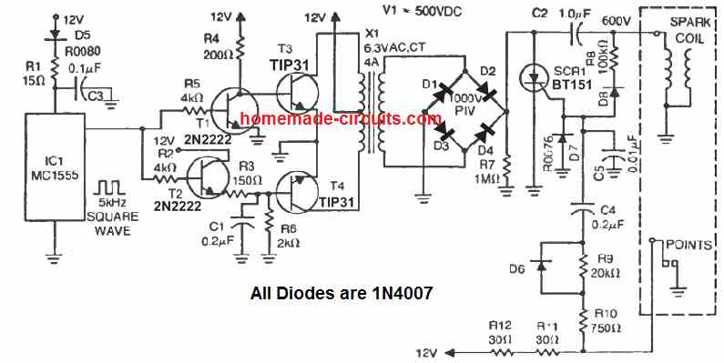
The whole concept for this electronic CDI can be understood by studying the shown circuit diagram below:
The diodes, the SCR and the associated components form a standard CDI circuit.
The high voltage of around 200V which needs to be fed to the above circuit is generated through an ordinary step down transformer connected the other way round.
The secondary winding of the transformer now becomes the primary and vice versa.
The low voltage primary winding is fed with high current pulsating DC generated by a standard IC555 circuit via a power transistor.
This pulsating voltage is stepped up to the required 200V and becomes the operating voltage for the attached CDI circuit.
The CDI circuit converts this 200V into bursts of high current for feeding the input winding of the ignition coil.
These rapid high current bursts are further amplified to many thousands of volts by the ignition coil and finally fed to the connected spark plug for the required arcing and the initiating the ignition of the vehicle.
As can be seen the input voltage is acquired from a 12V DC source which is actually the battery of the vehicle.
Due to this the generated sparks are very consistent without interruptions providing the vehicle a constant supply of the required ignition sparks irrespective of the vehicle situation.
The consistent sparking also makes the fuel consumption efficient, makes the engine less prone to wear and tear and enhances the overall mileage of the vehicle.

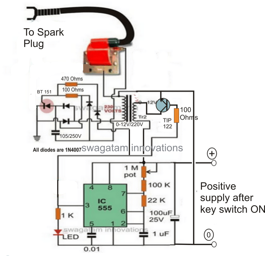
Use a 1K resistor at the base of TIP122...... 100 ohm is incorrectly shown
Synchronizing with Wheel RPM
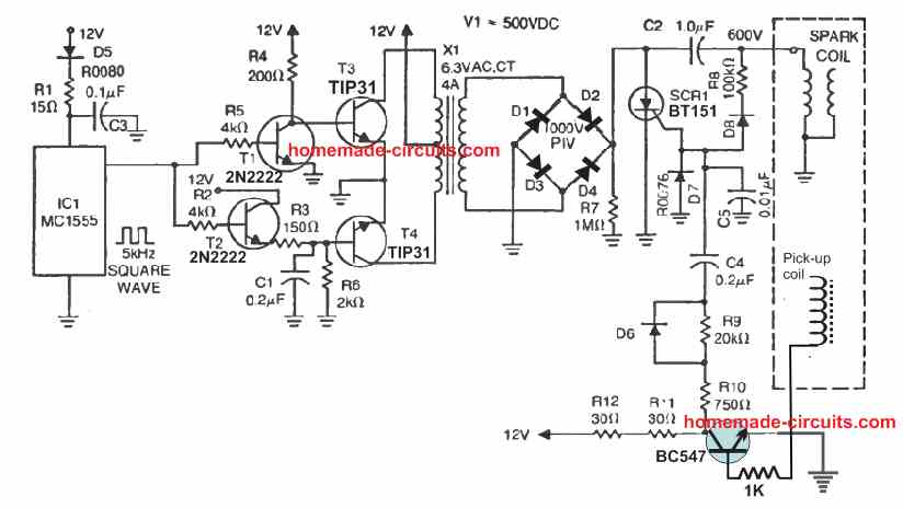
If you want the above circuit to be triggered by the alternator so that the combustion is ideally efficient and synchronized with the wheel RPM, the above design may be modified in the following way:
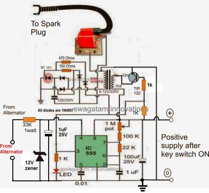
A 1K resistor is used at the base of TIP122...... since 100 ohm is incorrectly shown.
The above configuration may be further modified as shown in the following diagram, which appears to be the most appropriate way of implementing the proposed enhanced CDI circuit for all 2 and 3 wheelers.
How it Works
As we know, the reset pin#4 of IC 555 requires a positive potential to allow the normal functioning of the IC 555 as an astable or as monostable. If the pin#4 is not associated with the positive line, the IC remains dormant and disabled.
Here the pin#4 of the IC can be seen connected with the alternator voltage. This voltage can be of any level from the alternator, it doesn't matter, since it is appropriately stabilized by the 33 k resistor and the following zener diode, capacitor network.
The alternator will generate a positive and negative cycle pulses, in response to each rotation of the vehicle wheel.
The positive pulse will be converted into a 12 V positive feed at the pin#4 which will cause the circuit to initiate and stay activated during the entire positive pulse duration cycle of the waveform.
During these periods, the IC 555 will operate and fire the SCR multiple number if times in short bursts, causing the ignition to fire with higher efficiency and for a sustained period of time during the firing angle of the combustion and the piston.
This will also enable the CDI to work in tandem with the wheel rotation generating an ideally synchronized combustion of the engine and with an optimal efficiency.
Finalized Enhanced CDI Design with PWM Control
CDI PCB Circuit
Parts List
All resistors are 1/4w unless stated
1K - 1
10K- 1
POT 10K - 1
100 Ohms 1/2 watt - 1
56 Ohms 1/2 watt - 1
Diodes 1N4007 - 9
Capacitors
1uF/25V - 1
0.01uF/50V Ceramic - 1
105/400V PPC - 1
Semiconductors
IC 555 - 1
Mosfet IRF540 - 1
SCR - BT151
Transformer 0-12V/220V/1amp - 1
CDI ignition coil - 1
Video Clip showing the Test Result of the above shown electronic capacitive discharge circuit system
Another Version of Electronic Ignition
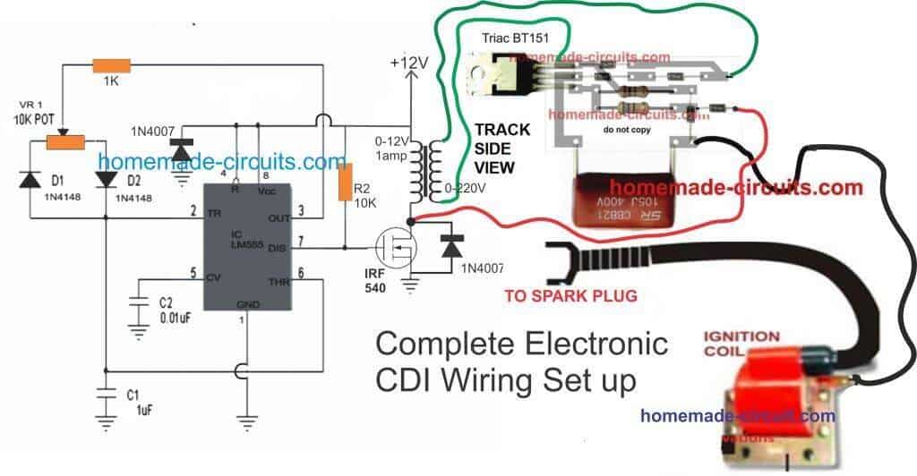
The following diagram provides another version of a IC 555 based electronic ignition system, which I got from an old magazine page:
Here, the left side stage which includes the IC 555, 4 transistors and the X1 transformer, form a 12 V to 500 V step up push pull inverter.
The right side section using the SCR BT151, and the associated circuitry forms the capacitive discharge ignition stage.
The design works with the old contact breaker type of mechanism, for timing the ignition and triggering the SCR.
While the contact beaker remains closed, the SCR remains disabled, and this allows the capacitor C2 to charge via the 500 V DC from the inverter output. Next, as soon as the contact breaker opens, the SCR gets its gate trigger via R9, 10, 11, 12, and C4, and it fires causing C2 to discharge across the attached ignition coil primary winding, which in turn causes the secondary of the ignition coil to produce the required high voltage pulse into the spark plug for the required ignition.
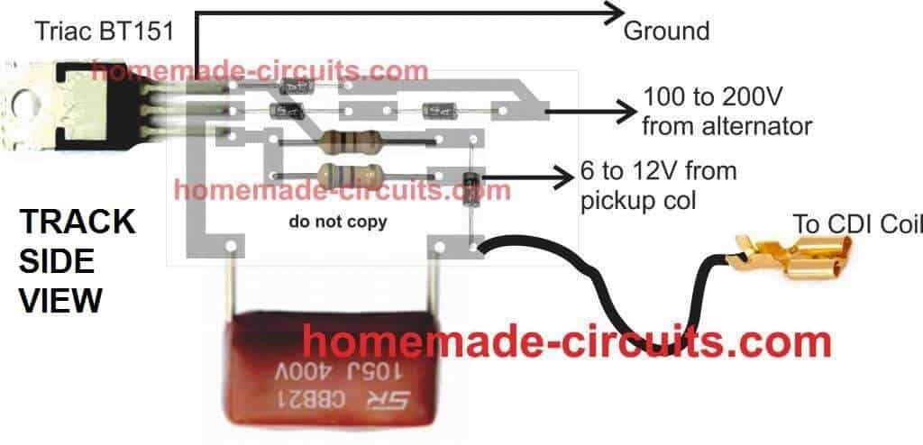
With Pickup Trigger
In modern vehicles we find the contact breaker being replaced with a pickup coil, which ensures a solid state working of the system without any wear and tear. The above electronic CDI design could be also used with pickup coil set up, with the following given modifications.
Hi Swagatam,
Does it triggered on the rising edge ( when voltage just want to go up) or the falling edge of the trigger signal?
Instead of the pickup I need to use another external 12V square wave as the trigger and spark should occur on the rising edge.
Thanks in advance.
Hi David,
Yes, the sparks in the above CDI circuits are designed to be triggered with the rising edge of the input pulses, so your square waves will be fine with these circuits…
Good evening sir, i made this circuit but even pin 4 of timer ic disconnected from pin 8 still pin 3 has an output is it normal?
Hi Elmar, pin#4 must be grounded through a resistor or directly, only then pin#3 will be disabled.
also, do you have any ideas on how to set up a spark measurement device to measure the strength of the CDI pulse?
For this application, I think you can select one of the circuits given in the following article and integrate it with an LM3915 bar graph LED generator circuit:
https://www.homemade-circuits.com/2-simple-rf-detector-circuits-explored/
Thanks for this article. Can you tell me what the diagram looks like when you add a tachometer feed? i think i know where, but i’m not sure.
thanks.
The above CDI circuits get triggered by an external pulse, which can be from a pickup coil of the automobile or an oscillator circuit such as a 555 astable, so the feed for the tachometer can be also taken from the same external trigger source which drives the CDI pulses.
Hello sir, can i use this circuit as a cdi unit tester?
Hi Elmar, yes, you can definitely do that!
Thank you sir, i also found your circuit design cdi tester.
No problem Elmar, all the best to you!
Let me know if you face any problems with the implementations…
Hello, thank you very much for your articles, I have something to ask. Where will the power from the control coil go in your design? ”Synchronizing with Wheel RPM”
My English is not very good, I hope you understand and answer.
Hi, referring to the following design, the synchronizing input from the wheel RPM must be connected to the point labelled as “6 to 12V from pickup coil”
" rel="ugc">
Thank you for your reply.
I made the CDI AC circuit as you instructed, it works very well, thank you again. But today, when I connected them to the “”Finalized Enhanced CDI Design with PWM Control”” circuit there was no spark. I measured the voltage at the output of the transformer as 374v AC. I used a 12v – 0 – 12v 3A symmetrical transformer, which steps down the voltage from 220v AC to 12v AC (is this a problem?). The circuit ran for about 3 minutes then the irf540 and the 1n4007 diode connected to it burned out. Can you advise me where I went wrong?
I think the MOSFET burned due to high voltage spikes generated from the CDI coil.
You can try replacing the MOSFET with a TIP122 BJT, because BJTs are more dependable than MOSFETs, and remember to connect the 1N4007 diode, either across the collector/emitter of the BJT or across the BJT collector and positive DC of the circuit.
Also, please connect a 100uF/25V directly across the supply terminals of the 555 IC.
Let me know how it goes..
Hello Swagatam, Thank for share you ideas with us. so i have a question regarding the last diagram. so i need to know can i use 12v-0v-12v / 220v normal transformer for it. that means 50Hz/60Hz one? if it can’t which type of tranformer i can use or can you give me the turns for primary and secondary coils.
And other one is can’t i use trigger pickup coil for your second diagram “Synchronizing with Wheel RPM” ? if it can how can i put it.
Thank you!
Thank you Avish,
Yes, the transformer can be any normal iron-core 50Hz/60Hz step-down transformer, you can see it in the adjoining video.
If you are looking for a pickup coil triggered CDI circuit, then you can simply use the diagram explained in the following article, no need to build the above complex design.
https://www.homemade-circuits.com/how-to-make-capacitive-discharge/
Nice article, You have an idea on how to proceed is there is no battery (one a one magnet fly wheel + CDI). The cdi is down and I would like to realise one with a microcontroller for the advance timing.
If there’s no battery then you can use the following circuit:
https://www.homemade-circuits.com/how-to-make-capacitive-discharge/
Sorry, i have no idea how to implement advance timing with microcontroller.
I would like to charge an extra electrolyte in order to serve as power supply for the microcontroller (Pic or aduino nano (or another controller which boots up fast enough)), which would the calculate the delay (in function of the RPM) to discharge the capacity (without discharging the elco).
You can use a 6800uF/50V capacitor after a blocking diode 1N4007, and feed the DC to your microcontroller through a 7805V regulator.
m saying good night from Cuba.
I present my name is Jorge Luis, I have experience and elctronica and electricity of motorcycles: I am interested in making a DC CDI functional for a bike 200cc 4 timpo. Or it could also be a TCI.
Idida TCI, it works me down very well but when I give it revolutions the engine gets stuck.
Since you doylas thank you for your help,
Hi Jorge,
If you have a pickup coil in your bike, you can try the following CDI circuit, and check the results.
https://www.homemade-circuits.com/how-to-make-capacitive-discharge/
Buenas la pregunta es este sistema de cdi le servira auna moto bicilindrica de cuatro tiempos cb350k4
Good day. I was wondering if you have a version of the CDI circuit that only uses 12-15VDC from a battery?
I do not have a magneto nor do I have an alternator.
Hi, The first circuit will work exactly as per your specifications. As long as the circuit is powered with 12V, the ignition coil will keep generating the sparks. The frequency of the sparks will be equal to the frequency of the 555 oscillator circuit
hi sorry a little off exact topic but i crossed activator wire for the kill switch that runs directly to cdi and now my engine wont run. sarter motor was engaged while wire was connected what am i facing for repairs? pick up coil and stator design.still getting good firebut wontfullyhit and run
Hi, sorry, I am not an automobile expert so it will be difficult for me to help you with the situation.
hello swagatam first of all i’m sorry because it is weak in english what is the
receiver coil you are talking about? (is it a module) ?
Can you explain with a diagram how to connect this circuit to my 1991 model 1400 engine honda civic? my vehicle has 4 cylinders and electronic ignition system. There is a module in the distributor, should I cancel it. I am a little confused.
Thank you in advance for your help
Hello Burhan, the circuit explained above is intended for 2 wheelers or 3 wheelers, it can be also used for cars but I do have the full information regarding how to connect it to a car ignition system…you may have to consult a qualified car mechanic for the connection details.
Hello there. First of all, I would like to thank you for sharing really nice projects. here is my question. I have a vehicle with a distributor, it has electronic ignition. How can I connect this circuit you shared to my vehicle? my car is 1991 honda civic with 1/4 engine
Hello, you will have to supply 12V DC to the IC 555 circuit. Next, you can disconnect the red wire which is connected to the MOSFET drain, and connect it to your pickup coil output. Finally connect the high tension wire from the CDI coil with the spark plug.
Hi Swagatam Pl check the circuit of the 555 timer of Finalized Enhanced CDI Design with PWM Control, In which the 3 no. pin should be connected to the gate of the IRF540 and not on the pot. also the Pot should be connected to the pin no. 7 and not on pin no. 3.
Please correct if i am wrong, I made as per the circuit provided but the 555 timer burnt out frequently.
This Why I saying is all other circuits above are having the output 3 connected to the transistor.
Regards
Manish
Hi Manish, Using pin#7 as the output is also correct, but mostly pin#3 is used as the output, since it is able to provide both high and low outputs. Pin#7 can produce only low logic but no high logic that is why we need an external resistor (10K) for providing the gate voltage to the mosfet during the OFF times. That said both pin#3 and pin#7 can provide flip flop or oscillating outputs.
I have myself ">built IC 555 oscillator using pin#7 as the output and it never had any problems….if you want to use pin#3 as the output, you can very well do it.
An example design can be witnessed in the following article:
https://www.homemade-circuits.com/making-adjustable-electromagnet-circuit/
Dear Swagatam
Can you help/ share the schematics of the 35KV spark tester based on the similar lines. What We require is to test the 35KV spark testing on the low current on some meters. I tried to make you version but in the second tranformer from 220 – 12 volt and 12v to 220 Volt the voltages drop 80volt output and the 555 timer IC does not work.
Can you suggest a better circuit diagram using the car CDI.
Regards
MAnish
Dear Manish, I can suggest the above circuits only which can produce well over 27 kv. Both the designs that you tried are well tested by me (you can check the videos). Since you want the current to be low, a 2 wheeler CDI/ignition coil is the recommended option. All the above circuits are very good and tested by me. This CDI circuit is the one which is used in all bajaj motorcycles and rickshaws
Dear Swagtam : What I have done is converted the 12 V supply from transformer to 12V Dc thru connecting a bridge rectifier and feeding it to 555 timer circuit. the output of the 12 volt transformer is AC and again fed tot he input of the 12 to 220 V transformer , in which I am getting 223V Ac output.
Is it correct or not. Please confirm.
Yes that is correct, and it is the correct method of producing low current 220V for the CDI circuit, as explained in the last section of the above article.
Thanks for your great circuits. I have a Kohler 20HP twin cylinder that recently had the ignition coil fail. What I was hoping I might do is adapt your circuit to file the ignition coil salvaged from a 90’s GM. They use two (or three) coils to fire two cylinders in same manner as the Kohler.
What are the pin numbers of IC555 in the circuit pulled from a magazine. The circuit uses the conventional points for trigger.
Thanks
Thank you, you can surely try any of the concepts presented in the above article.
the 555 stage in the last two diagrams are actually IC 555 astable oscillator designs.
You can incorporate the first design from the following article, and replace it in the last two CDI diagrams
https://www.homemade-circuits.com/ic-555-oscillator-alarm-and-siren-circuits/
what if we add more cappacitance?
I need 125 cc dc cdi unit diagram
Which then goes through a bridge rectifier. There will always be a positive voltage at the anode of the SCR all the time the oscillator circuit is working, so it will never turn off after the initial pulse to the gate.
I’ll take off my modification and see if I can get it to work as you have shown.
There’s no bridge rectifier here, even if we had one, still there would be huge breaks in between to enable the interrupted switching of the triac.
Bridge rectifier doesn’t mean the DC is pure, the DC will still be intermittent, unless a filter capacitor is added.
But how will the SCR turn off?
I checked with circuit simulators and my oscilloscope, but no negative voltage was ever applied to the gate of the SCR to turn it off, and the anode was always kept at a high voltage.
Maybe because I removed the capacitor from the points that I got some switch bounce which affected the circuit. My modifications seemed to have solved the problem but I can’t stop there and will continue to work on the circuit.
As they say, if it ain’t broke, fix it till it is. 🙂
Many thanks for pointing me in the right direction, and for all the projects on your site.
SCR will turn off because the pulses from the transformer or the alternator are pulsating DC, they are not pure DC.
I built the circuit using points, but it didn’t work.
When the gate of the SCR receives a pulse from C4 it conducts, and will discharge C2, but as the high voltage generator doesn’t stop, the high voltage will still be present at the anode of the SCR, so it will stay on even when the gate voltage is removed.
I changed the circuit and put a 4.7K resistor between pin 4 (reset) of the 555 and 12V. This was connected via a 2N2222 to ground. Two 1N4007 diodes were placed in the SCR cathode to ground line to give about a 1.4 volts from the forward voltage drop of the diodes all the time the SCR was conducting and discharging C2. This 1.4 volts went to the base of the 2N2222 via a current limiting resistor, keeping the 555 turned off until C2 was fully discharged and the SCR had fully turned off.
Not sure why it did not work for you, it worked for me though, you can see this in the video.
Hi
I think your battery powered CDI circuit could be the answer to my problem. I have built an electric starter for my Honda XR650R but it does not crank it over fast enough to make a spark. It make a spark when kicked over. Would it be possible to supply the CDI from the battery when starting then when running use the standard system. Please let me know your thoughts I am a novice with electronics.
Kind Regards
Tim Bungay
Hi, surely you can try the second concept, by using a 1k resistor across pin4 and the positive line through a series press button.
While starting the bike you can keep this switch depressed so that the sparking becomes continuously available at the spark plug while cranking the petrol suction system. Once the engine ignites you can release the switch for the normal operations
Thank you thank you very much God bless you, my son will be able to enjoy his toy
No problem, wish you all the best, and I hope your son enjoys the project, and succeeds with it!
Let me know if you have any further problems!
Hello Mr. Swagatam!
Thank you very much friend, I will hope that you correct all the diagrams and I will make sure that they are all correctly synchronized with the alternator and the RPM of the vehicle, I wait for you, and that my son is waiting for him, he is excited, thank you very much thank you we wait.
No problem Mr. Jose, You can view the second diagram, it has been updated as per the discussed synchronization with the wheel RPM.
Please let me know if you have any further questions!
Hello Mr. Swagatam!
I recently got a 50cc 2-stroke motorcycle bike for my son. The system I had is a CDI that is powered by the 12v AC generator and it does not have a pulse signal, I wonder if this circuit can be used to update the one it has, besides that it would have to change for that to work, in the same way that you have it but without the pulse signal and that it only feeds from the generator.
Hello Mr. Jose,
Actually every CDI has to be synchronized with the vehicle RPM so that the ignition sparking and ignition combustion resonates with the vehicle speed and RPM.
Although having a battery operated CDI is more efficient, even that must be in sync with the speed RPM of the vehicle.
This feature can be also added in the above circuits by disconnecting the TIP122 base from pin3 of th IC555 and connecting it with the alternator voltage via a 100k resistor.
I will soon correct all the diagrams and make sure all are synchronized with the alternator and the vehicle RPM appropriately.
hello and thank you for putting this site up i was going through it all for past 3 hrs and trying to find a solution to my bike’s ignition problem . it is a 2 stroke twin cylinder with a dc cdi unit as stock equipment and wasted spark on one at all times meaning of the cylinders fires when piston is on BDC and waste and do nothing . it has a single cdi wire feeding the twin coils . when i bought the bike the previous owner ha removed the dc cdi box and re it with a low rpm single cylander ac cdi unit the bike starts runs out of juice at 4000 rpm and do not work with the stock stator electrical supply feeding it since it is made to work alongside with a charged battery…… . how and in what part of the circuit could i boost the power to get to the coils also it has the lighting coils which is not used and could i wire those to the ignition in primary generator to get higher voltage to the cdi box . note that lighting coils put out more amps and lower voltage .. then this bike fires once at 180 degree 2 times faster then this cdi has been design to do . how can get out of this hole . if i can built one then i gotta do it because parts are not available appreciate any help and if the above design could get boosted up to feed a twin coil at 10 k rpm …… thank you
Hi, the core of the ignition coil determines how fast it can be triggered, and here the core is able to tolerate well over 100 cycles per second, which is 6k RPM, close to what is needed by you.
If you use a ferrite cored ignition coil then the triggering could be achieved to any possible limit.
Hi Swagatam,
I have a problem with my old atv Polaris Xplorer 300 because It need a new cdi and because I live in Europe is hard to fiind a new one to be send under 20 days.
Can you help with a circuit for my atv , I am not very good in electronics but I have friends who can help me but i need an specific circuit because my cdi doesn t have trigger and work using just electricity from his coil .
I attach some pics from Polaris service manual with the circuitshttps://ibb.co/71tSxxx
https://ibb.co/88BJ09N
https://ibb.co/DbkmQPq
Thank you in advance.
Hi Otonel, The basic CDI circuit should be the same as given above, and can be applied for your vehicle also. However, the specifications of the various excitation wires are not known to me, therefore assigning those inputs to the basic CDI circuit can be difficult unless the details are exactly provided.
Tengo dudas sobre el valor de las 2 resistencias que van al Triac, me podria decir el valor de la de arriba y de la de abajo. Gracias de antemano
470 ohms and 100 ohms
hi dear sir god bless you ,i have designed some double coil for car and i am in the process of producing unfortunately 30 percent of productions is returned due to problems including leaks and arc from the inside ,
And I’m designing a test circuit for the coils before transferring,
I want to count the number of pulses that reach the candle through the output wire and wireless, that is, by wrapping some wire around the wire plug
((((Please enable an output circuit only to the extent that it activates and deactivates the transistor.))))
Thank you in advance
That I can count the number of pulses through the micro at mega
Hi Sedigh, you can build a Darlington configuration using two BC547. Wrap the base with the output wire through a couple of wire turns. Connect an LED across collector and the positive +6V supply and emitter to negative of the 6V. Make sure to have a 220 ohm resistor in series with the LED. See if this circuits works for you
Hi Swagatom,
I have a single cylinder 2 stroke engine with an A/C CDI it is only has one HV coil that also gives the trigger signal the coil has the charge wire from one end and the trigger wire from the other end. The coil has a resistance of 106 ohms and will generate 130 volts between the Pulse and charge wire when cranking the engine.If you ground the pulse or charge wire it will also give 130 volts (volts measured with aid of a Diode and capacitor) Could you please advise if you know of a schematicto make a A/C CDI for a single coil system
Kind Regards Peter Gale
Hi Ian, as far as I know a typical CDI requires a couple of AC triggering voltages from the vehicles alternator and pick up coil. One is high voltage of around 200V from the alternator, while the other is 12V AC from the pickup. I have no idea regarding the single coil system which you are referring to.
More info here: https://www.homemade-circuits.com/how-to-make-capacitive-discharge/
Does it work on motorbikes? Thank you very much
Yes it is specifically designed for motor bikes….
Hi,
I’m an old retired guy playing with a cool little chinese motor bike. The low rpm problems are my challenge and I Think your improved circuit is my solution. Also I want to fire my ignition with a hall effect sensor mounted on a movable plate using my old mag coil mounting screw holes in association with a new flywheel with a magnet mounted. When my clutch is in, my timing is retarded for starting and idling. As I engage the clutch, the spark advances.(old car, old motorcycle).
This link shows what I have drawn, and I would appreciate your most intense criticism.
https://drive.google.com/folderview?id=1WJ4we9wqDSKL_fTglKFidoGpmqg1V6qH
Rick
Hi, I wish I could help, but since I am not an expert in the automobile field it is difficult for me to assess your ideas.
I am an antique auto and motorcycle restorer, and I’m not having an issue with the mechanics, this is my first pcb and I was hoping for critique on that.
Thank you!
Rick
Hi Swagatam
Is it possible with AC or DC cdi box circuit output high voltage to run DC or AC motor?
Kcool, no that wont’ work, because CDIs have low current outputs
I have an old Tecumseh engine that has the ignition module. The charge coil outputs about 30 to 36 volt ac pulsed, one wire. The pickup is a grounding type contact. There is no 12v dc power available. How can I build a cdi that could replace this?
Use the last circuit in the above page…so you won’t need any external DC to operate the circuit.
Swagatam, I am Dan in the U.S., and your web page contains a lot of exciting information! My question, I am working on a 1970 VW Beetle, Type 1, 1600cc. Of the circuit designs you have posted, or still not posted to the Web, what do you recommend for upgrading my Classic, 4 Cylinder, 4 Cycle Beetle? Thanks! Dan
Thanks Dan, actually the above explained design is intended for 2 Wheelers, I am not sure how this can be modified for a car engine. A qualified motor mechanic perhaps would be more knowledgeable about this.
Swagatam, I do thank you for your reply! As I stated, I am enjoying researching the information that you have posted! My research revealed a circuit titled, “Multi-spark CDI Circuit”. I do believe that this is one that you designed for automobiles. Of which, I am scrubbing the drawings and schematics, (I was not able to locate a Parts List). From here, I do have 2 questions. 1) You note in the schematic, “To Trigger Circuit”. Is this an input from the Points system for Distribution timing? Maybe the Alternator? Something different? Please advise. 2) Near the Coil connections, you have (2) 680k resistors, in series, connected to another component before they reach the path to Ground. I am having difficulty determining what this component is. I read “MOV1S14K 275”. I have no doubt that my interpretation is incorrect. What is this item? By the way, might you have a Parts List you could share? THANKS again! Dan
Thanks Daniel,
The circuit was not designed by me, it was lifted from an expert pdf source. The trigger input is supposed to be from a pickup coil, every vehicle has one I guess. That part is an MOV or metal oxide varistor for suppressing sudden high voltage spike or transient from the ignition coil EMF.
The parts are actually exactly as given in the diagram…all the resistors are 1/4 watt 1% MFR, unless specified in the diagram.
All the capacitors are metallized polyester type rated at 100V except C2 which 1uF/275V,
If you have further problems, let me know I’ll clarify them quickly
Hi sir, thanks for this post, i really appreciate your work and effort. I have some question to ask sir:
1. can this circuit start a generator?
2. Is there any mean to add or connect a toggle switch circuit to it? Such that pressed the generator ignite and start up
Thanks Solomon, this circuit is designed to create sparks only, so I am not sure how the sparks can be used to initiate the generator ignition, because ignition system normally also incorporates a fuel injection system for injecting fuel into the combustion engine for the required combustion.
Thank you for posting this. I am working on a scooter and this will work nicely. I have copper clad board that I would like to make the pcb for this with but I’ve never done one with quite so many parts. Would it be possible for ease of assembly to get a drawing of the traces as you would do them for the final iteration of the ignition module?
I am glad it helped you, however I am sorry, designing the PCB can be difficult due to lack of time. In my free time I may surely try to update it.
I understand. If I find a suitable solution before then I will share it.
https://drive.google.com/open?id=1LeLGL19C6NNNx5M_hcFvfnzAcFLf_3RO
This is my first attempt. Whenever you have a moment to look at it I would appreciate any feedback you have.
Pin#8 and pin#5 connections needs to swapped, same for pin#6 and pin#7 connections, looks like the pin#5 to pin#8 were mistakenly counted in the opposite direction.
Thank you for that. Should it look something more like this then? I also want to double check that I have Q1 and R1 correct.
https://drive.google.com/open?id=12xC_cEH3voubulgAplrj5F24FG_tJdie
Looks OK, although it can be further improved as shown below:
" rel="ugc">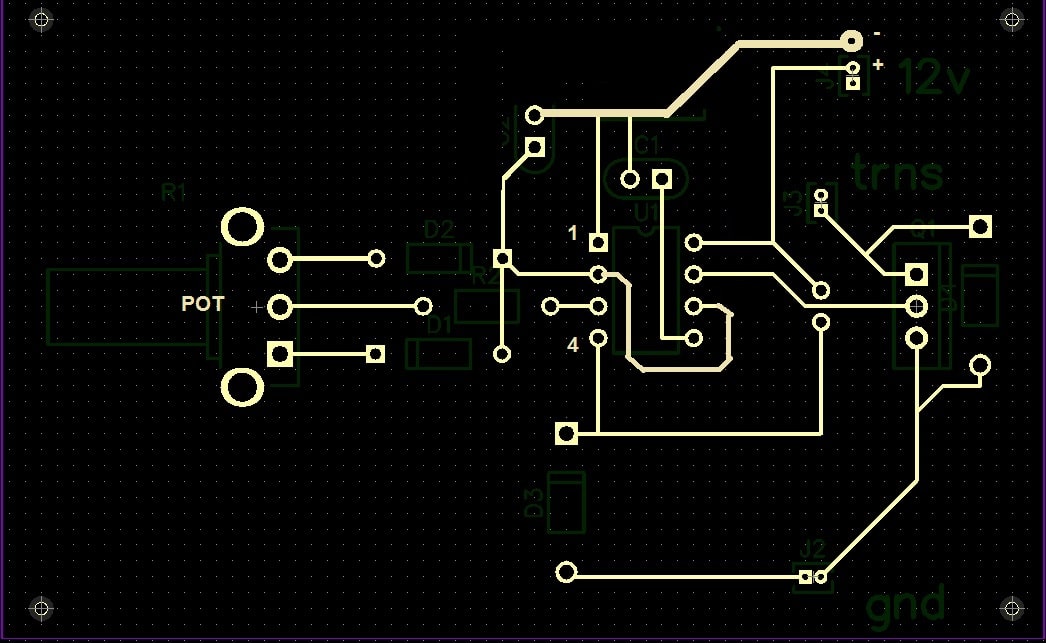
That does clean tings up nicely thank you. Your help was invaluable.
It’s my pleasure!
Also, I think you missed R2 in the PCB, which is very important.
You’re right I did miss that one – How would you suggest adding that?
You can add a pad on pin#7 track, and another pad vertically up connected with the positive line.
Gotcha – thanks again!
????
https://drive.google.com/open?id=1XK5UHQMSZXJhQ2ew10dBBxS-dmTXjZJK
I have this power supply, 220v to 12v – do you think it would be possible to use it for this project?
yes no problem, any DC 12V power supply can be used, current can be 1 amp or higher…
I am looking at the parts list and the diagram and can not see where the 105/400V is intended for. could you help?
Please see the brown big capacitor, and what’s printed on it!
Haha yes I noticed it shortly after I sent that message. The parts list says 10 1N4007 diodes but I only count 9 on the diagram
yes, looks like only 9 are there in the actual circuit, I’ll correct it soon in the parts list, thanks for pointing it out.
Hi! I have a ’67 Fiat 1500 and I’m planning to put a 3D printed rotor with four magnets in the distributor cam, replacing the points with a hall effect sensor (like this: https://www.youtube.com/watch?v=tlj5KYjAVn4 ). The modification by itself is easy to do, but also I’d like to use your CDI system… what modifications should I do to trigger the spark with the hall effect sensor? Would this ignition be powerful enought to work with an automotive ignition coil?
Regards from Córdoba, Argentina!
Hi, you can use the following configuration for your hall effect sensor, and integrate it the CDI circuit shown in the last diagram of the above article:
" rel="ugc">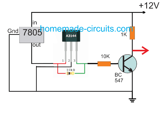
you can disconnect the red wire from the mosfet drain and connect it with the red arrow shown in the above linked diagram.
The series diode with this red wire is also not necessary and could be replaced with direct link.
yes this design will be powerful enough to work with any ignition coil. If required you may increase the 105/400V capacitor value to 2uF/400V for enhancing the power level.
hi Swagatam, I want to DIY and replace a faulty ignitor module or cdi for 12 volt, 3 cylinder car engine. Are there any circuit in your blog that suitable for me.
I have the photo of the cdi pcb board but i’m not sure about the component they use on the board. I am willing to pay a reasonable price for you to redesign/duplicate it.
Hi Kenny, I am sorry presently I do not have any schematic for car ignition system, but if you can explain the functioning details of the circuit then probably I can design it myself and present it here!
Hey swag,
You have been very helpful on this topic for fixing my seadoo. I have decided to use the circuit that utilizes the battery as my coil does not generate the 220 voltage. Just wondering what the arrows are that are pointed at the 2 resistors on this diagram. Hoping to get this project done this week and get the seadoo back in the water. Also being in canada the 12/220 may be difficult but I read your comment about 6/120 and using the 12V. For a 2 cylinder 2 stroke engine is there anything different I need or will your finalized diagram work? Thanks so much.
Thanks Adam, Those are the symbols for the diodes, which are 1N4007 in this design.
A far as I know, a timed triggering is always required for all ignition based driving systems, therefore in your system also a timed triggering should be incorporated, otherwise the sparking will just go on continuously inside the ignition chamber which may not be good for the system.
Before building and installing you will have to figure out some arrangement for enabling a timed triggering.
In automobiles this is done through a pickup coil, you can perhaps take the help of a qualified auto mechanic for getting this solved for you
I do have a pickup coil that is already part of the ignition system. Also I know which symbols are the diodes I am talking about the small arrows the to top right of the IC in the diagram above. They seem to be pointing to the resistors.
OK I think you are referring to the 1M and the 22K pots, those are potentiometers or variable resistors. You can learn more about them here:
https://www.homemade-circuits.com/potentiometers-pots-explained/
Excellent thank you I just wanted to be sure. I will try and build this before the weekend. The transformer is the hardest part to locate here as the common house voltage is 120V
Thanks Adam, I wish you all the best,
I have updated the finalized circuit and the video showing the test results.
I can not tell where the 12v trigger comes into the circuit on the updated circuit. Could you clarify?
Thanks
Please see the red wire going toward the drain of the mosfet, you will have to disconnect it from the mosfet drain and connect it with the pickup source
Also I know I am asking a lot but is there anyway you could make a parts list so I dont miss any. I found the transformer for 26 bucks! Great deal
Thanks again
I will try to update it soon…
Hi Swag.
I have two cylinders on my motorcycle. Each cylinder has two spark plugs. Can I use the above circuit?
Many thanks.
Joe
Hi Joe,
I am not sure about it, you may have to consult this with a qualified auto mechanic.
Hi Swag.
This circuit is perfect for me.
Can I connect two coils instead of just one?
Regards
Joe
Hi Joe, yes you can but even if you connect two coils both will fire at the same time, will that be OK with your ignition system??
Hi Swag.
Thanks for your prompt response.
Yes, two coils firing at the same time is what I am after.
I will build a second unit to handle the second timing pulse also firing two simultaneous sparks.
So, just to recap.
I can use two ignition coils in parallel or do I need to isolate them some way?
Thanks and regards
Joe
Hi Joe, It is still not clear to me.
You are saying:
“Yes, two coils firing at the same time is what I am after.”
then you are also saying:
“I will build a second unit to handle the second timing pulse also firing two simultaneous sparks.”
both sentences are contradicting.
If your have a “second timing pulse” that means the firing instances are different for the two combustion chambers?
In that case you will require two entirely separate circuits and coils to handle the ignition of the two combustion chambers.
Hi Swag.
Yes, this is correct.
Two timings pulses.
Each timing pulse fires two coils simultaneously.
Your example shows one coil only.
Can I connect two coils to each circuit without any modifications?
Thanks for your help.
Regards.
Joe
Hi Joe,
yes you can do that.
But please don’t try the circuit as yet, because when I recently tried building the circuit the IC blew after some time, I blew 4 ICs in the course. It might be happening because of the capacitor discharge entering the circuit. Somehow it seems the IC side needs to be isolated from the secondary side of the transformer.
I’ll try to fix this soon and update it for you.
However, when I had tried this 4 years ago that time everything had worked smoothly without any problems, I can’t remember what was the change that allowed this to happen?
Hi Swag.
First off may I congratulate you on your practical designs and you dedication to responding to readers’ questions.
In my own case I hope to build two of your dc cdi units.
I have a Honda 750 twin spark twin cylinder motorbike so I assume I’ll need two units.
Also, can I split the output to two coils or should I put in some isolation circuitry to feed each spark coil? Thanks and regards. Joe
Thanks Joe, I am glad you liked my work.
Regarding your questions, if your two units are designed to work with two different input signals with different timings from the pickup coil then splitting may not be a good idea, however if they are supposed to work together, simultaneously, then surely a single circuit can be used for both the units.
Thanks for your quick response Swag.
In my case, each circuit fires two sparks for each trigger signal.
Can I just connect two automotive coils in parallel or should they be isolated from each other (on separate feeds)?
Thanks and regards
Joe
Thanks Joe, if the timing of the triggers are identical then a single coil output can be bifurcated into two, however if the timing of the two triggers are required to be different then separate coils would become mandatory.
Thanks Swag. Appreciate your help, thanks!
Hi Swagatam, how do you adjust the timing coming from pickup?
Somehow i prefer not to do any mod on my bike magneto, so i still can use the original CDI
Planned to use this for emergency only.
Thanks
Hi Althaf, it cannot be done in this circuit, and manual adjustment is anyway not recommended, because that can cause inefficient operation of the engine.
All my local mechanics would just grind the (thing that activate pickup coil ? we call it “Bulge”, I dont know the name in english, sorry) then moving it to suitable position and then re-weld it, so that 1 to 2 type of CDI that is available in market would be usable for all type of bike here, regardless of different timing implemented on each bike.
But as I stated above, I prefer not to “grind” the magneto, so if one time my CDI is busted,(which happened long time ago) I could pull my handmade CDI, install it, continue in my way, and when I got home, I’m just swap it to the new one.
Thanks for the reply tho, will look up to your other interesting projects.
Cheers
OK understood, however the above circuit has no such feature which can adapt different switching rates as per user preference.
thanks for your fast response
LED is blinking and IC555 circuit work fine
OK great, please use 1K at the base of the transistor and make sure to connect a 1N4007 diode across the collector emitter of the 2N2222 otherwise it can get quickly damaged from the tafo back emfs…..anode to emitter
Hi boss can you tell me what is the ampere of given transformer
not exactly sure, it could be around 2 amps at the input side.
Dear Swagatam
I constructed this circuit but instead of Tip122 I used 2N2222.
then The circuit didn't work, I have tested all circuit connections,I measured the input voltage to transformer (at 12V side) , It was 0V AC,but I disconnect the transformer ,the measured open circuit voltage equal 19V AV.
Could you explain this issue?
Hi Ahmed,
Something is certainly not correct in your design…first make sure your 555 is generating the required pulses…to check this reduce the frequency to some lower level by increasing the pin6/2 capacitor value to say 10uF and then adjust the pot and check the LED response…it must blink…if that's not happening then your 555 circuit is faulty and needs to be diagnosed
by the way 2N2222 could become hot while switching a 1amp trafo.
thanks for your reply
so could I use any non polar capacitor such as film capacitor
105/400V must be non-polar…you can use any type rated at 400V or above
thanks for your reply
Is it rated 400V AC or DC
you are welcome!
400V is the breakdown voltage limit of the capacitor, any voltage whether DC or AC if it exceeds this limit the capacitor will burn.
Dear Swagatam
sorry but I could find BT 151 and 105/400V could I replace them with any LED and 1uF 250V elect Capacitor?
c
Dear Ahmed, BT151 and the 105 components are the two crucial parts of the circuits and cannot be replaced by anything else
Sorry, but could you provide me links for those component or more details about component
you can check out the datasheet of BT151 for more info, 105/400V is a PPC capacitor equivalent to 1uF/400V
this is very useful,I want to make this circuit could you tell me type of capacitor please?
thank you very much, just copy the parts as indicated in the diagram…the shopkeeper will be able to provide you the correct ones.
I need a circuit with 5 joules output energy So I have some questions
How much power this circuit can provide ?
What is the type of transform?is it a pulse transformer?
what is the number of transistor device?
I have not measured the output power so can't specify that, the transformer is an ordinary 0-12/220V iron core step down tansformer, please click on the diagram to get all the details…
Hiya Swatagam! I'm located in the US, and am attempting to build a CDI to replace a faulty one on my 1978 Honda CB400T Hawk. After reading through the comments, I found what the value of the pot is supposed to be for (could this same CDI design be used for inline 4 cylinder motors as well?), so that question is answered. However, going through the parts list and attempting to locate components has not landed me with much success. The 105uF/250V capacitor, for example, I am having a really hard time finding. The only results I've come up with so far are the size of soda cans (which is impractical for mounting and use on the bike) and rated only for intermittent use in, say, starting an electric motor. Does it *have* to be a 105uF capacitor, or can it be, say, 108uF (I ask because 108uF caps seem to much easier to find on supplier sites like Mouser electronics)? The 0-12V/220V transformer has also proven very difficult to locate. Do you have a supplier that offers these things, by any chance?
Thanks so much for posting the schemata, and for your assistance!
Marcus Cross
Thanks Marcus, you can use the same the design for a 4=stroke motorcycle also, although the CDI coil specs could be different for different models, and can be exchanged as per preference.
105 = 1000000pF = 1000nF = 1uF, and 108 = 1000000000pF = 1000000nF = 1000uF/250V…wow that's huge!!…it can be used in place of 105/250V but could be unnecessarily bulky and costlier…but you can try it out it won't cause any harm.
By the way the "105" is not 105uF…it is short code for identifying a capacitor value universally.
getting a 220V trafo in US could be difficult since your country utilizes 120V for the mains….there's a workaround you can try for acquiring 220V from a 120V transformer, you can use a 0-6V/120V transformer instead and the output will be almost 220V provided the circuit is powered with a 12V
Hello Abu Hafss,
I want to switch to exiter coil after starting the bike to ensure the inverter circuit is not damaged due to over heating due to prolonged use & to prevent drainage of battery in bike.
Regarding spark timing, in royal enfield old models there is a distributer assembly/points for timing control,in cdi models(only 2002 model)there is a relucator arm which has a magnet,it is attached to the crank shaft,when this magnet moves near pulsar coil a pulse is generated in pulsar coil which is passed to the cdi unit,now the cdi circuitry decides the spark timing which varies in different types of cdi-units as different engine cylinders have different cubic capacities(in enfield it is 500cc & 350cc)..
i would welcome your clarifications on this.
Thanks
Hi Sandeep
I understand your concern about the spark timing. Please note that the spark timing has nothing to do with the engine displacement (i.e. cc) instead it depends upon the RPM of the engine. You can find many universal type of CDIs for racing bikes, they all work on RPM.
Here is the design which only works with inverter module.
" rel="nofollow ugc">
The modifications are indicated in red boxes. You need to add a fast recovery diode like UF4007 to convert high frequency AC into DC and then input to CDI.
The set-up in the lower red box is to pause the oscillation of the IC at the instant when the a positive pulse is received from the pulsar coil. This is important because SCR within the CDI demands the current across its MT1/MT2 to be zero. Moreover, this increases power economy as all power supplied during discharging is wasted otherwise.
For design which allows both inverter and exciter coil, I shall update soon.
Okay Sandeep, here you go.
This new design includes a 555 monostable timer circuit for about 3 minutes.
As soon as ignition switch is switched ON, this timer is also triggered. Hence, for approximately 3 minutes the Inverter will provide HV to the CDI via relay contacts. After 3 minutes, the 12V supply to the inverter is diconnected and also the CDI input is linked to the HV from the exciter coil.
" rel="nofollow ugc">
Thanks for your suggestion Abu,
I think by simply replacing the stock cdi of royal enfield with that of bajaj discover would not serve the purpose as the spark delay mechanism (pulsar coil/timing pulse)work differently & may lead to misfiring,sorry for contradicting your statement but i feel that cdi swap would create more hassles.
Here my purpose is to bypass the exitor coil in order to provide better voltage to cdi unit at low rpm(kicking phase) for easy starting.The timing or triggering mechanism would remain unchanged.
Pls suggest me some way to connect the inverter circuit just for starting the bike…once it starts the input to cdi unit should continue from the exitor coil completely bypassing the output from inverter.
I thought of deploying a manual switch to control a change over relay but looking forward for some better & more efficient approach.Also would like to know about the protection aid to cdi from 30khz square wave ac generated by the dc-ac converter module(i am not aware about the property of ac generated by exitor coil,if its of a hi frequency then the query is resolved automatically).
Pls take your time & help me over coming these hurdles.
Hi Sandeep
Firstly, please note that the spark delay/advance is not performed by mechanical parts. It is done by circuitry inside the CDI. Secondly, those delay/advance are required in Racing/Performance bikes not in commuter bikes.
Anyway, if you insist to do it in your way its your choice. Let me study the circuit of the inverter. But why you want to switch to exciter coil after the bike is started? Why don't you power the CDI continuously with the inverter? It will make the circuit more complex unnecessarily.
Sandeep
First of all, please tell me if you want a hassle-free solution or you want to do all the work by yourself.
1) For a hassle-free and cheaper solution, simply go to your bike mechanic and ask him to make modifications in the wiring so that you can use a DC-CDI. After googling, I found that Bajaj's Discover 135 has DC-CDI. It is very easy to know if the bike has a DC-CDI or AC-CDI. If there is an Exciter coil in the stator then it has AC-CDI if not then DC-CDI. Another way, if a CDI unit has a HV-AC input then the CD is AC type and if has a 12V supply then it is DC type. You can buy any DC-CDI and the mechanic will do all the minor modifications. The modifications are:
a) Provide a 12V supply line for the CDI from the ignition switch
b) Replace the existing female CDI connector with a connector compatible to the new CDI.
c) Tape/Insulate the output of the existing exciter coil
The advantage of this method is that in future, if for any reason your CDI stops working; you simply need to replace the CDI with a new one.
2) If you want to do all the job by yourself, even then you do not need such high powered boost converters for CDI. CDI needs less than 70W.
If you still want to use this module, please give me some time to study it then I might be able to suggest you minor changes in it and the CDI circuit.
Hello Sandeep
You might need proper integration the pulsar coil input with the module and the CDI. For that please share the circuit of the module. Moreover, you would also need some modifications in wiring and ignition switch.
Thanks for your prompt reply Swagatam,
what my main concern is if 110v ac @ 25khz is applied to stock ac cdi unit,would it burn the internal rectifier circuitry or damage the capacitor inside cdi unit..
pls reply..
Thanks Sandeep, the capacitor will not be affected due to the high frequency, but if the diodes are not rated to handle the high frequency then it could lead to problems….so before installing you can check whether the diodes are appropriately rated or not
Hello friends,
I own a royal enfield 2002 model which has a cdi ignition.i am planning to perform some mods in order to facilitate the cold start.
it has an exitor coil which charges the capacitor in side cdi unit,also there is a pulser coil which precisely gives the timing pulse according to the piston position .
Now in due course of time as the exitor coil( produces around 100-150v @ 3000rpm) winding becomes weak there fore is unable to produce enough voltage to charge the capacitor as a result lots of kicking is needed to start the bike..
To get rid of this issue i have decided to put a module which simply replaces the exitor coil.The module converts 12v dc(from battery) to 90v square wave ac @ 30khz frequency,this ac output is feeded to cdi unit,what i guess is that this mod would fully charge capacitor of cdi instantly & when kick is applied the timing pulse(from the pulsar coil) would triger the discharge the capacitor through scr tothe primary winding of ignition coil & would produce better sparks & hence better ignition.
i would like to seek advice from the learned members of the group on the feasibility on this prospective mod.
Hello Sandeep, your idea is perfectly feasible and you can surely implement it in your bike a hassle free performance. In fact the last design in the above article is exactly what you have explained in your comment, except that it uses an iron core transformer and your module has employed a ferrite core transformer to keeps things compact
Hello sir
So you have a CDI for 2 cylinders engine ( honda shadow steed 400cc NC26)
Tq
Hi T.Q.
Here we have a CDI for 2 cylinders engine but that has 6 wires. Whereas, the CDI for your model has 10 pins. However, I think our design can be used on your bike. If you could show the original CDI labeling the pin-outs, then I can finally confirm if it is usable or not.
where in UK can obne buy one of those little transformers?
Hello Curt,
I am not quite sure about the "retard" function as explained by you, may be you know it better and so it could work fine as assumed by you.
As far as using 12V for the spark is concerned, I am afraid that won't be possible and you would require an ignition coil for that which would in turn require an intermediate step-up transformer for raising the 12V from the battery or the magneto to approximately 100V for the ignition coil primary and for initiating the sparks across its high tension cable end.
Sorry………….."This design is MOSFET type for dual stator coils…..
Hello
The design which Swagtam has recommended is a 3-phase Fullwave rectifier. You may try the following design:
https://www.homemade-circuits.com/2012/10/motorcycle-full-wave-shunt-regulator.html
This design is MOSFET type for dual alternator coils. Just eliminate the lower bridge rectifier and you will get a 4-pin RR-unit. If you need an SCR type, please wait until July 20th.
hello, here's one design which matches your requirement, you can try it:
https://www.homemade-circuits.com/2016/02/motorcycle-shunt-regulator-circuit.html
please elaborate
it's 25V, non-polar is not required, an electrolytic will also work
It's not O, it's zero (0), it goes to the negative of the battery
TIP 122 is at the 12V side of the trafo.
Hello 🙂 Sorry if I did not understand or found the information, but, is this circuit an improvement over existing industrial grade CDI on a motorcycle (ex. a 125cc suzuki model 2008) ? Or is it just over existing contact breaker (magnetic) older ignitions ? Thanks
it's an improved version of the electronic CDI which are currently used in all standard two and three wheelers, it's not for high speed vehicles which involve critical "forward" or "retard" timing for the ignition.
The 1M pot is for adjusting the frequency of the pulses, and the 22k PWM determines the width of the pulses.
In straightforward terms the 1M determines the number of sparks per trigger from the pickup coil and the 22k pot determines the strength of the sparks, or the current involved in the spark, higher PWM will generate stronger sparks and vice versa.
As far as optimization is concerned that will need to be done with some trial and error or you might have to take the help of a qualified automobile technician, alternatively you may also refer to the credible online sites for getting more info regarding the subject.
I looked at the diagram, and I don't quite understand how the signal is sent to discharge the capacitor into the spark plug. Is it done on its own when you cut off the power from the battery?
when the SCR is OFF, the capacitor charger up, and as soon as as the SCR is triggered, it shorts the other end of the cap to ground allowing the full charge to dump inside the ignition coil.
see the capacitor ends, one is connected to ground via the SCR, other is also connected to ground via the ignition primary.
Thank you!!!
This is brilliant and it will get built! I like the simplicity of just using a flipflop to drive the Hf generator that is nice! Unfortunately i will be away the next 2 months but as soon as i return i will start.
some questions; on a 6cyl with 3stage CDI this will operate at total spark outputs of up to 400Hz. Will the primary driver support this much draw??
Also Automotive coils connect using 2 wires normally, one is constant power and the other is the switched signal in this case should one just be earthed? and if so which one?
does the duration of the trigger signal matter? if so what should i set this to? (aftermarket ecus have this option)
Does the coil fire at the start of the signal or the end??
And lastly does it matter what type of capacitors are used?
Hi Rama
It is better to continue further commenting under the actual article. So, I have replied there:
https://www.homemade-circuits.com/2015/12/dc-cdi-circuit-for-motorcycles.html
yes i can make that no problem 🙂
I have seen some pictures and explanations on other forums etc so just point me in the right direction for the size and type of parts i need, i am staying in Taiwan at the moment so there is a lot of electronic stuff available here!!
I would like to make this as powerful as we can! i dont mind if it draws a lot of current thats no problem. So if we can bump the OP up over 100Mj would be really nice.
can we do 3 channel then i can test it on my own car (6cyl) they will always be fired at even intervals apart so the primary generator wont need to feed any channels at the same time.
cheers
Hi Rama
You may find the desired circuit in the following article:
https://www.homemade-circuits.com/2015/12/dc-cdi-circuit-for-motorcycles.html
By the way, I have made these CDIs with 240V and the output was strong spark across 1" spark gap. You can change the zener values to achieve 350-400V. But the rating of C6 should be much higher accordingly.
No they will not all fire simultaneously. Almost all 4 stroke engines have 2 cylinders that are paired so only i coil (connected to 2 spark plugs) will fire at a time the other one/s will fire at the alternate ignition events driven by a separate trigger signal, Yes aftermarket ECU's have up to 8 completely separate ignition trigger signals….
yes we could just have 2 or 3 totally separate units but i would like to have everything contained in one unit if possible, and im thinking there would be some way to share some of the circuitry…
…so im thinking you could have one heavier current step-up section to provide the ~400v then have two (or 3) separate CDI coil driver sections with a separate trigger signal for each one to drive the coils independently….possible??
That way i could use 2 (or 3) duel post coils attached to 4 (or 6) spark plugs and have then all fire at the correct time in wasted spark configuration 🙂
this is exactly the way we often do it now inductively using simple transistor based igniters but the spark strength is often not strong enough for turbo and high performance applications.
Okay, I got it. Yes, as you proposed, we can have a HVAC generator section which could be shared by each channel. But that section includes a calculated/customized transformer which is the key to successful generation of HVAC. Those ferrite-core transformers are not available with stores or suppliers, you have to built each piece using EI cores, bobbins and some magnetic wires. If you can do that, I will help you for the circuit.
Okay, now what I understood from your description is that you need a 2-channel or 3-channel CDI unit. Each output of the CDI unit will be connected to a Dual Post Ignition Coil which will provide 2 sparks. Hence, you can get 4 sparks (or 6 sparks) simultaneously.
But in a 4-cyl or 6-cyl engine, the spark plugs are not supposed to fire simultaneously. The firing timing in each cylinder must synchronize the TDC position of the piston in that particular cylinder. How would you do that?
If the ECU has 4 (or 6) separate (output) trigger pulses then you would need a simple 1-channel CDI + single coil + spark plug for each cylinder.
Ok most engines these days dont have distributors anymore, they have a coil for each spark plug or in many cases have a duel post coil that fires 2 spark plugs at the same time, this is called "wasted spark" since only one of the two sparks is actually getting used each ignition event the other one just fires into the empty cylinder at the end of the exhaust stroke, so in this configuration a 2 channel CDi will run a 4cyl and 3 channel for 6cyl and 2 x 2 channel for v8 etc… There are many different brands of ecu and they all have the ability to produce a 5v signal for each cylinder
ps, Most aftermarket ECU provide a 5v square wave ignition signal but some also have an option to provide a ground signal directly to the coil (ie built in igniters)
Thank you.
Ok I help a lot of racing friends install and tune aftermarket ECUs, They are fully programmable and very universal these days, completely replacing the original ecu. One of the most common situations is turbo fitted to a usually non turbo engine. Often the first thing to cause problems and limit the bosst and power output is the strength of the spark! So if i could build a nice easy 2 or 3 channel CDI then use duel post coils this would solve the problem for 4 and 6cyl engines without having to go and spend hundreds of dollars on brand name cdi units
Rama Diaz
I shall appreciate if you would provide a link about the universal ECU, you are talking about.
Next, you don't need to have different CDI for each cylinder. One CDI unit would be enough to produce spark. In a multi cylinder engine there is a distributor which distributes the spark to each cylinder based on the timing set by the rotation of the camshaft. However, for a V8 engine you would need two separate CDIs.
Maybe, I have not understood your actual requirement correctly. In that case, I would request you to elaborate further, if possible with the aid of block diagram.
ok thank you and is it possible yo make multiple independently triggered channels without repeating the entire circuit?
yes that's possible, please let me know the details of the application, I will try to design it.
Hi i have limited understanding of detailed circuit operations but that has never stopped me building many interesting projects in the past!
I have some questions about the triggers, you have 2 circuits with 2 different trigger input configurations. If i was to use this on a car triggered by an aftermarket ecu which one would i use?
would i use a 5-12v signal or an earth signal?
and does the length of the signal matter? 1ms? – 5ms?.. etc
and does the spark event always happen at the end of the signal?
thank you
Hi Rama,
a positive 5 to 12V trigger will be required for the second and the third circuits, the length of the spark could matter, I am not very sure about its significance…but it's said that multiple sparks for some fraction of a second gives better results than one abrupt strong spark…
To me the second circuit makes more sense…so you could try that.
Hi Rama Diaz
1. It is very strange for me to use an "aftermarket ECU" for getting triggering pulse. According to my knowledge, the latest model cars have sophisticated computer circuitry (ECU or ECM) which controls almost all the electronic gadgets installed in the car. And they are quite expensive.
What I understand from your statement is that you are trying to install an ECU on an old model car (which previously had the old triggering system). If that is the case, I am afraid you might not be successful because the ECU's are made for a specific engine, they are not universal type of device.
2. The circuits shown above are designed to fire on a positive trigger signal. If your ECU is firing negative signals, you have to get them inverted before using with the above circuits.
3. Yes, the length of signal impacts the burning behavior of the fuel/air mixture inside the cylinder. The engineers of a car engine define it based on complicated calculations under different operating conditions. And, the same they pre-define in the ECU.
4. The above circuits fire the spark at the moment they receive the trigger pulse.
Hi. Firstly I want to say thanks for making your schematics available.
I am currently working on a arduino based ecu (speeduino) and would love to know if the cdi design above has any form of "advance" built in.
Also what form of input does it need to trigger, would a 5v square wave, from an arduino pin going high, be sufficient?
you are welcome, appreciate it.
No this circuit does not include the "advance" feature
yes a 5V oscillating trigger would be sufficient for producing the proposed results.
By the way I have discussed one advance/retard design in the following post:
https://www.homemade-circuits.com/2015/05/adjustabe-CDI-spark-advance-retard.html
Thanks I actually don't need the advance feature as I am thinking of trying this circuit on an ECU of sorts. I have bookmarked your website however and intend to come back to read in the future.
Thanks again
A. Berthfield
You are most welcome!!
Hi swagatam. Is there any complete parts list for this project?? I am having trouble reading and figuring out some parts. A list would be very helpful, just like the other cdi post you have. Thank you
Hi Mikel,
Please click the diagram to enlarge it, you'll find the part numbers clearly indicated beside the respective component symbols, if you still have problems please let me know.
0-12 transformer is how many amps? And trigger should be in primary section or in secondary?
1 amp,………….. trigger should be on 0-12V side
Hi Swagatam.
Congratulations for your super interesting demonstration.
I work on a small project with a small HHO generator 4 stroke 190 cc 6.5 hp.
We must completely change the CDI.
I will use your system, I use 2 hall effect HO44E.
1 hall effect that cancels the second spark via NE555
Another hall effect trigger in use.
I must use the circuit with the pulse triger, right
what type of diode used
Thank you in advance
Happy new year for 2015
Michel
Hi Michel,
If you have the schematic idea you can go ahead with it and I am sure it would work.
The diode can be a 1N4148 or similar.
Wish you too a very happy 2015.
Swagatam Majumdar mir bitte etwas TR2, bin ich sehr dankbar
Please write in English…
yes TR2 can be 0-12V/260V 1amp
Hi swagatam,
how about old car with breaker point, can use this circuits ?
Thank you
Hi Jipi, yes surely it can be replaced with the above explained circuits.
Hi swagatam,
I have some some queries regarding this circuit.
Can this unit be used for plasma ignition ?
Can we use non resistor spark plugs ?
Amit
Hi Amit,
The above circuit has no relation with plasma ignition, so it cannot be used there.
By resistance do you mean a suppressor? Yes may be suppressor can be eliminated if the PWM from the 555 is correctly adjusted for minimum interference.
I have modified the circuit becomes like the link below
https://drive.google.com/file/d/0B6BNp6ufIZwEN3BlZ2ViRzkyT1E/view?usp=sharing
https://drive.google.com/file/d/0B6BNp6ufIZwEektLMmhNUzVWSk0/view?usp=sharing
circuit above works by changing the signal from the trigger into a box-shaped signal,, then the signal was used to trigger scr,, which is the case I only have one output while in your circuit to generate HV should require two inputs,, … directly of the trigger,, and from pin 3,,
btw if this circuit dc cdi? of the second link above picture,, Which can make HV work? or do you have another solution my friend ?? 🙂 Thanks
Abdul, If we connect the SCR gate also to the pick-up pulse trigger, it wouldn't allow the SCr to sustain it's firing process the moment the pulse moves away…the SCR needs to have a continuous firing trigger so that once the capacitor is charged it's able to sustain the discharging of the cap until fully discharged.
therefore in both the diagram suggested by you the SCr would be unable to sustain its firing process due to the intermittent make and break action of the trigger pulse…
ohhhh,, so the pulse output from pin3 burns continuously in a fixed frequency, unchanged and not affected by a trigger signal from the pickup pulser,, not used for triggering scr, but the signal from the trigger is converted into a high voltage to be used to fill capacitor ???
if that's the case,, capacitor can not be fully charged because when the capacitor in the charging process, scr has been opened by a signal from pin 3, thank you friend
The charging process will be much faster since it's been done directly through the transformer output and at a powerful rate…where as the discharging process is been done in pulse mode and the ignition coil resistance is also in series which slightly slows down the discharging process compared to the charging process…
friend, means pin 3 will continuously deliver signals to scr, although there is no signal from the trigger?
means pin 3 provides the same frequency kecepata,, at high and low rpm?
yes that's correct pin3 continuously provides the gate voltage but the SCR switches OFF and stops responding as soon as the capacitor is fully discharged for a particular cycle
the pin3 is only responsible for chop single sparks into multiple streams….the pickup trigger actually decides at what rate the the capacitor must be charged/discharged, not the pin3 of 555 output.
thank you very much,, friend Your explanation is very helpful 🙂
you are most welcome, friend!
I am still confused,, friend hehehhehe
mean signal issued pin 3, is the same as the signal generated by the trigger, only the signal from pin 3 is a box-shaped signal, while the trigger is an early signal,, before the signal is converted into a square and raised by a transformer to be used to fill capacitors
how menghhubungkan if I only have one output of the timer module? whether it is in a parallel output into 2 lines, 1 towards scr, the other lines connected to tip22 as input transformer
…………………… ____________
from trigger —— | ………………. | ______ output to tip22
……………………| Timer module |……|
12 v —————- | ……………….. |……| ___ to the scr
or leading scr form of a trigger signal into parallel paths
………………. _____________________ To tip 22
………………..|…._____________
from trigger__|__| ……………….. | ______ output to scr
……………………| Timer module |
12 v __________| ……………….. |
What should I do if I only have one output? such link above, what is supposed to fill the transformer which will be charged to the capacitor I took from the motorcycle battery
friend, if you drive the transformer and the ScR with the same output from the pin3 of the 555, the CDI would keep firing continuously wasting a lot of battery power unnecessarily.
The transformer and TIP122 are basically for rendering the CDI independent from the alternator, while the 555 is positioned for enabling multiple sparks from the CDI, in other words for breaking the capacitor discharge through many isolated sparks per fraction of a second.
Friends, I want to ask .. what's the use of the pulser signal near the tip 122? for triggering scr should use a signal pin 3 of ic 555 ???
btw is there a replacement of tip 122? in my city is hard to find these types,,
i4.minus.com/jMqCEgiZubCk6.jpg
please check the link above ,for example as shown in the link, the picture explains that the HV generator circuit is only using one input signal conditioning of the trigger signal to the circuit scr . Thank you
Abdul, the trigger signal is the 5V timing pulse voltage from the alternator.
With every trigger pulse the HV capacitor is charged up by the transformer stepped up volatge, and the SCR immediately starts firing it through rapid pulses, at a rate determined by the 555 astable frequency…the firing is sustained until the capacitor is fully discharged ….and the cycle repeats with the next trigger from the alternator..
TIP122 could be replaced with a 8050 or a 2N2222, or a D1351 transistor…
oh everything is clear, thank you very much .. friend
you are welcome, friend!
My pleasure, Abdul Hamid…. 🙂
one more question,, friends,,what is the function of a 1M pot? thanks
it's for determining or setting the number of sparks per trigger from the alternator.
oh yes thank you very much for the answer
Friends, I want to ask again
1. What if the higher voltage, it can be a big fire in the spark plug? because fuel with octane > 100 take a long time and a large fire to be burned, it can be burned properly if cdi ignition have advanced and large fire
2. I understand, the ignition timing can be made only forward or backward when using the micro controller, but hard to find complete schematic cdi
according to me under no circumstance the engine can catch fire, no matter how you manipulate the sparks.
higher voltage switching will only mean wastage of energy but no harm to the engine or the spark plug….
now I understood what you meant by forward and backward spark timing, it can be done using discrete components too… but will need some thinking….
Abdul Hamid
I assume, by "big fire" you mean strong spark at the spark plug. That will definitely yield more power.
As far as ignition timing is concerned, yes it can be achieved only using a microcontroller because trigger timing need to be adjusted at high RPM. But that is required only in performance/racing bikes, the normal commuter bikes run fine without them.
Dear, Abu-Hafss
right, because i work for motorcycle racing team , and motorcycle have specifications compression ratio of 13: 1, for fuel use aviation gas with an octane rating > 100, for it takes more power and advance timing to burn fuel with an octane rating > 100. to solve the problem of the time I use a programmable cdi ignition, so I can change the degree of timing at each RPM, but not whether more happy and proud if cdi cdi used are homemade, hehehe, hehehethanks
Dear Abdul Hamid
Hmm, what I understand is that now you are using some ready made programable CDI, purchased from some store. And that you are interested to make your own…..right?
In that case, you may email me at abuhafss@hotmail.com as that topic becomes irrelevant to this particular article. 🙂
Hi ,Swagatam Majumdar
I wanna ask about this cdi..
1. this cdi convert 12v to 200v ,, usualy cdi convert to 350-400v ,, can i give 350-400v to this cdi ? if the voltage is small means cdi have small power to spark plug?
2. can i give trimmer for advance timing,, example: i want to advance my ignition by 4 degree, or retard 4 degree
3. how many rpm maximum limit SCR on this circuit ?
4. how to take a tachometer signal from this cdi
Thank you so much
Hi Abdul,
1) if a 220V trafo is used the output would be 220V and it's more than enough for egnerating the sparks.
2) retarding or advancing the timing may not be possible because the circuit is dependent on the actual triggers from the alternator,.
3) any desired rate of RPM can be applied.
4) from TIP122 collector
Dear Abdul Hamid
The normal 70cc to 125cc commuter bikes have AC-CDIs (powered by high AC voltage from source coil). And the magnitude of that voltage is about 180VAC. Only a few models have DC-CDIs (with built-in HV inverters) but, their magnitude is also around 200-250VDC. And as Swagatam has mentioned, that 180-250V are more than enough.
However, sports/performance bikes or bikes with more than 200cc have DC-CDIs which generates more than 300VDC.
….yes, and since the spark plug gap is not more than 2 mm, even 100 V into the CDI is sufficient for inducing the sparks..
Dear Abu-Hafss
I from indonesia, Here almost all dc motors has an ignition system (with inverter) I have 2 motors suzuki Satria r (RGX – 2 stroke) tuned 120cc to 125cc and Satria fu (Raider150 – 4stroke), and there is also dc cdi made in Indonesian for racing use have high output + – 380 v, but too expensive 230 USD , Thanks
Dear Swagatam Majumdar,
yes friend my motorcycle sparkplug have gap 0.7 – 0.8 mm. Thanks
hi
got the scr bit, the part im wondering about is- if i work backwards from the 100ohm resistor the not the fist junction but the second that runs through a diode then down to the wire that connects the capacitor to the coil. is it mearly an earth circuit for when the capacitor charges. i couldnt work out why a connection from the capacitor would run up to the 100ohm resistor
Hi, it's probably positioned for grounding the negative half cycles through the 100 ohm which takes of the sting considerably and keeps the SCR in a safer condition.
hi
forgive a beginers question can i ask the purpose of the part of the circuit that runs from the ignition side of the capacitor through a diode to the 100 ohm resistor
john
hi, it's called SCR, the number used is BT151, it's there for switching the capacitor stored voltage over the ignition coil primary…
Hi bro
Can you tell me this cdi I can use for yamaharx135?
yes bro you can use it…
hi sir…my bike is AC-CDI, I used DC-CDI now…
my question is,can i use the HV from stator for HID?
Hi nhark, which circuit are you referring to? exactly where do you intend to use the HV from the stator n the circuit…please clarify these.
Jaycobs ladder it is then good day sir.
clearly you have no idea how a piston engine works or cdi's in general , a cdi that uses' the stator for for high voltage do not generate any high voltage at all, the scr just passes the already high voltage from the cap which got charged from the from the stator to the igniton coil.
look at your first circuit , it continuously sparks from power on, EPIC FAIL!!
second circuit i have already outlined the problems which you are not grasping.
rename the circuit head title to "Jacobs ladder" that's what you really designed a CDI it is not.
i have told you how to fix it , you don't listen so take it on the chin.
I am not considering the first circuit, it was just an initial attempt….may be you did not go through initial comments above.
When I said high voltage I was referring to 100-200V from the alternator…may be you are too busy imposing your own theory here so have lost your patience and understanding.
It seems you are just an ordinary auto-mechanic, it's a complete waste of time talking to you.
meaningless when the circuit doesn't work for a engine which it was intended, the advantage with your circuit is that it creates high voltage for the coil, which would make any engine start way better. your description doesn't explain that where trying to achieve multi spark cdi anyway
actually all CDIs are designed to generate high voltages with the help of the available 100-200V from the alternator, the advantage of the above circuit is that it does not rely on the alternator voltage which could fluctuate with engine speeds making the procedures inefficient, rather the circuit makes use of the battery voltage for supplying a consistent power to the ignition system.
the second circuit was designed by me after some research and suggestions from the readers and later on I realized that the design could be well modified for generating multiple sparks which was a bonus to the existing design.
The 555 signal allow the capacitor to get discharged through multiple sparks by breaking the charge into many pieces instead of dumping the entire voltage instantly as we have in ordinary CDIs. This perhaps helps to produce a smoother transition to the engine speeds and combustion.
However the second circuit needs slight modifications, I'll hopefully do it soon.
at 1000rpm on a single cylinder 2 stroke, sparks every 16 seconds, which is already faster than the astable output making the 555 circuit useless , isnt the scr and tip122 just going to stay on because the r/c timing for the 555 never going to discharge fast enough to go low, run the 555 separately in astable just fot the charge circuit for the cap , trigger the scr directly, then the circuit would work fine, forget multispark with scr arrangement.
without multi-spark feature the whole purpose of the design would become meaningless and it would become as good as an ordinary CDI as given here:
https://www.homemade-circuits.com/2011/12/how-to-make-capacitive-discharge.html
maybe its the terminology been used thats making it confusing , as the alternator does not provide timing , the trigger coil does for cdi , in cdi circuts the cap is always charged with stator then the scr is triggered when needed, the circuit above looks like the 555 astable output goes to the scr and the 12v coil, so looks like even if i triggered it at the correct time it has to charge the cap and trigger the scr at the same time? but wondering does the scr turn off when the 555 output goes low?
the scr will surely turn off due to absence of the gate trigger and also the 200v charge voltage from the transformer….only during the short trigger periods from the alternator the SCR will get the chance to fire may be in the form of bursts of multiple sparks….
the main intention here is to make the scr fire the capacitor through multiple sparks even after the transformer is been switched OFF, but it seems the present circuit is not designed to do this.
the circuit could be modified to do this by including a small value capacitor across the junction of the gate 470 ohm resistor and the diode cathode…this will allow the scr to be in the firing mode for a few millisecond more until the high voltage capacitor is completely discharged for every trigger pulse from the alternator.
Tiaki Senior has a point. Your circuit is sparking all the time, there is no way of triggering it to coincide with the position of the piston. It may work, but will fire much too early for low rpm at tickover.
the second circuit is not sparking all the time, it's synchronized with the alternator through its pin4…. I hope you know how IC 555 works.
hi bro,
what is the difference between the alternator ang magneto,rectifier?
both are electricity generators, "alternator" is derived from alternating current which forms its output while "magneto" is from the magnets involved in generators for generating electricity.
move the scr to the secondary side so we can trigger when we need spark, leave the 555 pulsing the primary keeping the cap charged, this circuit will not work its sparking all the time
sorry, No! the above circuit must be built just as shown, I have tested and verified the design practically.
How can it spark all the time when pin4 of the IC is connected with the trigger signal??
Hi Edgar, you can probably do it by isolating its existing trigger input and integrating it with a 555 astable input as shown in the second design above.
The 555 circuit could be powered from the 100V source itself after stepping it down and rectifying into a clean DC through a capacitive power supply.
Hi there Swagatam, I plan to retain my existing motorbike cdi and instead insert and adjustable spark delay circuit still triggered by the alternator pulse signal. Hence, driver must accommodate 100vac+ fast switching? Is there a mosfet for ac switching? Or, the other way around, can the existing OEM CDI accept a dc pulse? Thanks again, friend!
Hello Edgar, the input at pin4 should be actually from the trigger coil of the alternator, yes the zener diode will make sure that the signals are appropriately stabilized before it reaches the IC.
oops, sorry, didn't notice the zener diode… please disregard & delete previous inquiry. Thanks again.
Hello Swagatam, is the trigger pulse from the alternator AC? If so, need to rectify it before pin#4? Thanks again.
Hi Edgar, the second circuit actually includes the feature, please see on the left of the circuit (pin4 of the IC)
Hi Swagatam, thanks and appreciate your prompt reply. In both circuits above, the 12v input trigger pulse from the alternator is not indicated. I believe, it is to pin#2? Regards!
Thanks Edgar, sure! you can try retarding the sparks by employing the spark control facility provided in the enhanced version of the CDI circuit
Best Regards.
Hello Swagatam, I have been following this blog for quite sometime now and very impressed for your unending and unselfish support for those who are in need. Great job.
I have an HHO installed on my motorbike and I need to retard the spark timing. I plan to build your enhanced CDI with a spark timing adjustment incorporated in it.
Please advise. Cheers!
Dear Sir,
This circuit can be use for small mist blower?
can't say, have no idea about it.
thanks
Dear sir,
This circuit can be use for 2 stroke motocycle (150cc)?
Is it making spark plug longer life time and bigger spark?
thanks
Dear nuraniku,
yes it can be used for 2 stroke engines, and will create more efficient sparks than traditional CDIs
Nice CDI Man!!!
How is it triggered???? Is a Piggy back design? it would produce a capacitive spark each time the original vehicle inductive fires???
It would be nice having the two sparks (original inductive and added CD) working together. Original inductive long lasting and CD high peak…
Regards
Thanks Athal,
Please see the second diagram, you can trigger it through the alternator by connecting the ICs reset input with the alternator pulses.
The number of sparks per alternator pulse can be adjusted by the setting up the 1M ppreset accordingly
Dear Swagatam,
I was speaking about the DC 12v battery powered scheme (not the AC from alternator). The scheme shows the DC 12V + and – conexions but I can't see the triggering input. Because of this I was wondering if this unit Works as a piggyback of an inductive OEM system (negative is also triggering). Having both inductive and capacitive spark discharging simultaneously (using HV diodes to protect inductive circuit) would be great (like MSD Stacker or Pertronix second strike).
Again: nice Project!
Where can i download any PCB drawing an list of components?
Thank you.
Dear Athal, it's triggered via the pin3 of IC555 through the 470 ohm resistor into the gate of the SCR.
The 555 IC output at pin3 does a dual job of creating the 220V AC for feeding the capacitor as well as triggering the SCR for the required discharge sparks.
Sorry, PCB design is not available as it would be quite time consuming for me to design, your PCB maker would do it very easily.
The parts can be easily noted down from the diagram itself, just click on the diagram to enlarge it. All the components are standard, resistors are 1/4watt 5% CFR
Dear Athal
The triggering should sync with TDC position of the piston. For that particular reason the motorcylces' flywheel are equipped with a small raised metal strip and pick-up coil is installed at a position that it sync with the TDC of piston. Thus the triggering frequency is directly proportional to the RPM.
However, in the captioned circuit the 555 will trigger the sparks at a constant frequency, irrelevant of TDC position. I cannot simulate how this circuit will behave when installed. Please do share your practical experience.
Thanks & regards.
Thank you Abu-Hafss!!
hi sir can u please tell me if this cdi ignition circuit can be used in old point ignition enfield bullet and how i can wire it because a pair of wire coming from alternator to point then capacitor.please elaborate it with diagram for bullet with point ignition.
Hi Arindam, a modern cdi circuit can be replaced with all types of previous contact breaker type of cdis.
I am not very sure about their wiring, I think it would be better to consult an auto electrician, he would be able to provide the right solution.
Actually it should be "ignition coil", wrongly written as trigger coil.
The ignition coil would be already present in the vehicle, it will need to be integrated with the assembled circuit as given
Hi Swagatam
A regular 220v/12v-1A transformer would be quite large if we consider the size of genuine CDI units. Can we shrink the size of the transformer, like using a toroidal core? Or some other method?
Hi Abu-Hafss,
Yes that's true, very soon I would possibly post an identical article with a ferrite core transformer.
Shall be waiting…..
Hello Ustaad Jee
Normally, the two wheelers have 6V batteries. In that case won't the need to be 220v/6v? What would be the amperes?
Hello Guruji,
Can you specify which two wheeler today uses 6V? I have never seen one.
But anyway, yes the trafo primary V rating would depend and should match the battery voltage.
Hmm, perhaps you are right. Actually, I never owned/driven a bike, only car. Earlier, the bikes had 6v batteries and I assumed they are still having the same set-up. Thanks for the up-date.
By the way, just for learning sake, if it is 6V system what should be the amperes?
lower volts would mean higher current requirement for lights, horns etc that's why 12V batts are preferred instead of 6V today.
Current isn't much of an issue here because the spark plug gap is so small that even a 500mA trafo would work nicely.
Recently I posted another related circuit here:
https://www.homemade-circuits.com/2013/10/universal-multi-spark-enhanced-cdi.html
Hi Swagatam
As discussed in an earlier post under the 555-12V BOOST CIRCUIT, I integrated that circuit with the CDI circuit.
" rel="nofollow ugc">
The output shown on the left is the one without the boost circuit having AC input from the two-wheeler itself.
The one on the right is with the AC supply from the boost circuit. As mentioned earlier, the supply is about 220VAC varying between 0-220V. It could not be rectified. As per your suggestion, adding another 10uF capacitor drops the voltage to 160V.
You can see the difference between the two outputs. The points at which the voltages were recorded are marked in the circuit. In the left circuit you can see there is constant rectified 200VDC. The response to the trigger can also be noted. Whereas, in the right circuit the voltage is not rectified.
Any suggestion?
Still waiting for the CDI with ferrite core transformer, which you proposed on Oct. 11, 2013.
Thanks Abu-Hafss,
I'll look into it and reply you as soon as I figure out a suggestion.
Hi Abu-Hafss,
Can you please isolate the the CDI and the 555 boost circuit and then perhaps confirm the voltage waveform of the 555 stage? This would help us to know the origin of the negative pulses, if it was from the boost circuit or the CDI coil?
Also the bjt stage could be removed (as it looks immaterial) and a 1N5402 added parallel to the 10uF cap in the boost circuit
Here's the link of the proposed ferrite core cdi circuit:
https://www.homemade-circuits.com/2013/10/universal-multi-spark-enhanced-cdi.html
Hi Swagatam,
How is the coil triggered? Is this done by completing the ground after the BT101?
Thanks in advance,
Matt
Hi Matthew,
Yes that's right, it's when the SCR triggers….. the capacitor discharges via the ign coil.