In this post I have explained a few circuit concepts which can be employed for converting or modifying any ordinary square wave inverter to sophisticated sine wave inverter design.
Before studying the various designs I have explained in this article, it would be interesting to know the factors which typically makes a sine wave inverter more desirable than a square wave design.
How Frequency Works in Inverters
Inverters basically involve frequency or oscillations for implementing the boost and inversion actions. The frequency as we know is generation of pulses at some uniform and calculated pattern, for example a typical inverter frequency may be rated at 50Hz or 50 positive pulses per second.
The fundamental frequency waveform of an inverter is in the form of square wave pulses.
As we all know a square wave is never suitable for operating sophisticated electronic equipment such as TV, music players, computers etc.
The AC (alternating current) mains that we acquire at our domestic mains outlet also consists of pulsating current frequency, but these are in the form of sinusoidal waves or sine waves.
It's normally at 50Hz or 60Hz depending upon the particular country utility specs.
The above mentioned sine curve of our home AC waveform refers to the exponentially rising voltage peaks which constitute the 50 cycles of the frequency.
Since our domestic AC is generated through magnetic turbines, the wave form is inherently a sine wave, so doesn't require any processing further and becomes directly usable in homes for all types of appliances.
Conversely in inverters, the fundamental waveform are in the shape of square waves which needs thorough processing in order to make the unit compatible with all types of equipment.
Difference between Square Wave and Sine Wave
As shown in the figure, a square wave and sine wave may have identical peak voltage levels but the RMS value or the root mean square value may not be identical. This aspect is what that makes a square wave particularly different from a sine wave even though the peak value may be the same.
Therefore a square wave inverter working with 12V DC would generate an output equivalent to say 330V just like a sine wave inverter operating with the same battery but if you measure the output RMS of both the inverters, it would differ significantly (330V and 220V).
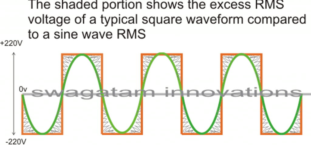
The image incorrectly shows 220V as the peak, actually it should be 330V
In the above diagram, the green colored waveform is the sine waveform, while the orange depicts the square waveform. The shaded portion is the excess RMS which needs to be leveled of in order to make both the RMS values as close as possible.
Converting a square wave inverter into a sine wave equivalent thus basically means allowing the square wave inverer to produce the required peak value of say 330V yet having an RMS just about equal to its sine wave counterpart.
How to Convert/Modify a Square Waveform to Sine Waveform Equivalent
This can be done either by carving a square wave sample into a sine wave form, or simply by chopping a sample square waveform into well calculated smaller pieces such that its RMS becomes very close to a standard mains AC RMS value.
For carving a square wave to a perfect sine wave, we can employ a wien bridge oscillator or more precisely a "bubba oscillator" and feed it to a sine wave processor stage. This method would be too complex and is therefore not a recommended idea for implementing an existing square wave inverter to a sine wave inverter.
The more feasible idea would be to chop the associated square wave at the base of the output devices to the required RMS degree.
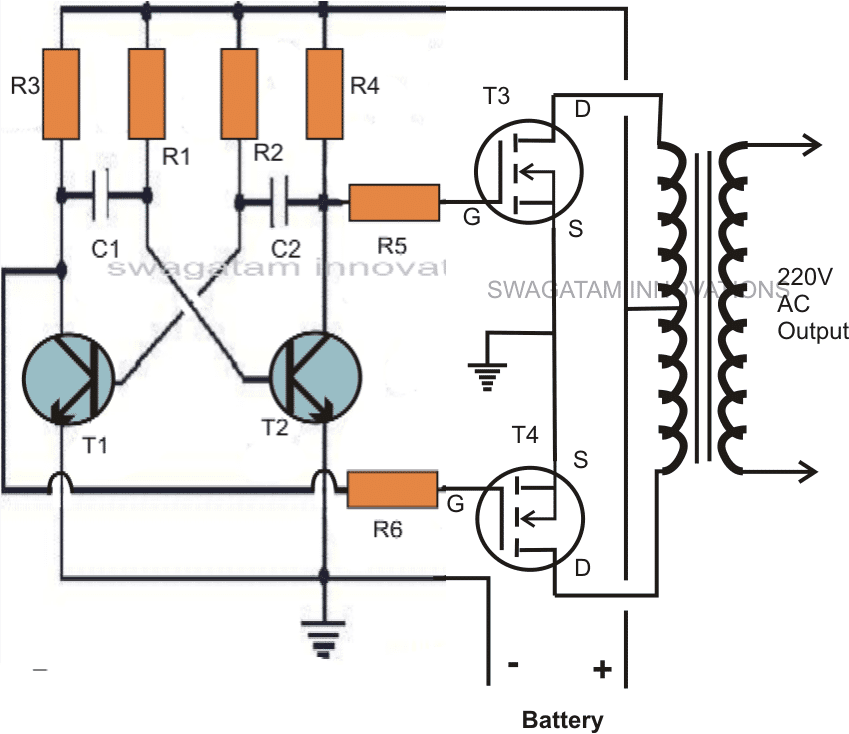
One classic example is shown below:
The first diagram shows an square wave inverter circuit. By adding a simple AMV chopper we can break down the pulses at the base of the relevant mosfets to the required degree.
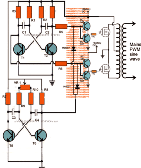
Modified square wave to sine wave equivalent inverter version of the above circuit.
Here the lower AMV generate pulses at high frequency whose mark/space ratio can be suitably altered with the help of preset VR1. This PWM controlled output is applied to the gates of the mosfets in order to tailor their conduction into the stipulated RMS value.
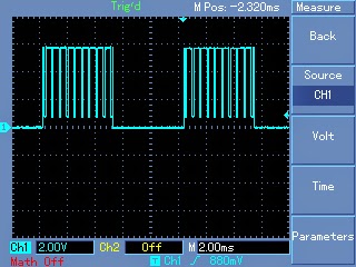
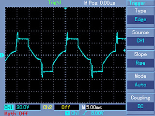
Expected typical waveform pattern from the above modification:
Waveform at the mosfet gates:
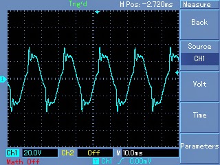
Waveform at the output of transformer:
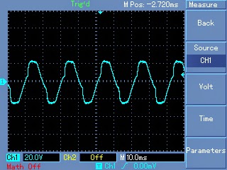
Waveform after proper filtration using inductors and capacitors at the output of the transformer:
Parts List
R1, R2, = 27K,
R3, R4, R5, R6, R7,R8, R9, R10 = 1K Ohms,
C1,C2 = 0.47uF/100V metallized
C3, C4 = 0.1uF
T1, T2, T5, T6 = BC547,
T3, T4 = any 30V, 10amp mosfet, N-channel.
D1, D2 = 1N4148
VR1 = 47K preset
Transformer = 9-0-9V, 8 amp (specifications must be selected as per the output load for correct powre optimization)
Battery = 12V,10AH
Getting Better Efficiency Rate
The above explained conversion or modification will provide around 70% of efficiency with the achieved RMS matching. If you are interested in getting better and precise matching then probably a an IC 556 PWM waveform processor would be required.
You would want to refer to this article which shows the principle behind modifying a square waveform into a sine waveform using a couple of IC555.
The output from the above mentioned circuit can be similarly fed to the gate or the base of the relevant power devices which are present in the existing square inverter unit.
A more comprehensive approach may be witnessed in the this article where an IC 556 is used for extracting precise PWM based modified sine wave equivalents from a square wave sample source.
This waveform is integrated with the existing output devices for implementing the intended modifications.
The above examples teach us the simpler methods through which any existing ordinary square wave inverter may be modified into a sine wave inverter designs.
Converting into an SPWM
In the above article I have explained how the waveform of a square wave inverter could be optimized for getting a sine wave kind of waveform by chopping the square wave into smaller sections.
However a deeper analysis shows that unless the chopped waveform is not dimensioned in the form of SPWMs, achieving a proper sinewave equivalent may not be possible.
To satisfy this condition an SPWM converter circuit becomes essential for carving out the most ideal sinewaveform from the inverter.
The basic idea is to chop the output power devices with sine wave pulse width modulation, so that the power devices force the transformer winding to also oscillate in the SPWM mode and ultimately generate an optimized pure sine wave at the secondary side. The magnetic induction of the pulsed SPWM across the transformer winding finally gets the shape of a pure sine wave due to the inductive filtration of the transformer winding.
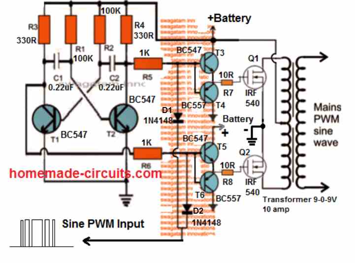
The following diagram shows how this could be effectively implemented with the concept discussed above.
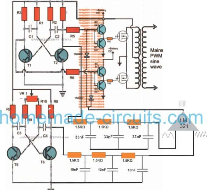
Through one of my earlier articles we understood how an opamp could be used for creating SPWMs, the same theory could be seen applied in the above concept. Two triangle wave generators are used here, one accepting the fast square wave from the lower astable, while the other accepting slow square waves from the upper astable and processing them into corresponding fast and slow triangle wave outputs, respectively.
These processed triangle wave are fed across the two inputs of an opamp, which finally converts them into SPWMs or sine wave pulse widths.
These SPWMs are used for chopping the signals at the gate of the mosfets which ultimately switch the waveform over the connected transformer winding for creating an exact replica of a pure sine waveform at the secondary side of the transformer through magnetic induction.
How to Calculate the Part Values
Astable Multivibrator Frequency (Square Waves):
Formula: f = 1 / (0.693 * (R1 + 2 * R2) * C)
For the fast square wave generator:
Let R1 = 10k ohms, R2 = 100k ohms, C = 10nF (example values).
ffast = 1 / (0.693 * (10000 + 2 * 100000) * 10e-9)
ffast = 1 / (0.693 * 210000 * 10e-9)
ffast = 68 Hz
For the slow square wave generator:
Let R1 = 10k ohms, R2 = 1M ohm, C = 100nF (example values).
fslow = 1 / (0.693 * (10000 + 2 * 1000000) * 100e-9)
fslow = 1 / (0.693 * 2010000 * 100e-9)
fslow = 7.1 Hz
RC Integrator Cutoff Frequency (Triangle Wave Generators):
Formula: fc = 1 / (2 * π * R * C)
For each RC stage assume R = 1.5k ohms and C = 33nF.
fcstage = 1 / (2 * 3.1416 * 1500 * 33e-9)
fcstage = 1 / (2 * 3.1416 * 0.0000495)
fcstage = 3223 Hz
For three stages the overall response rolls off steeply approximately at the same fcstage.
Op-Amp SPWM Generation:
The op-amp compares the fast triangle wave (carrier) and the slow triangle wave (modulating signal). The output is high when the carrier is greater than the modulating signal. This generates a sinusoidal PWM (SPWM).
Gate Drive Requirements for MOSFETs:
Formula: Ig = VSPWM / Rg
Assume VSPWM = 10V and Rg = 1.5k ohms.
Ig = 10 / 1500
Ig = 0.0067 A (6.7 mA)
This ensures the MOSFET switches efficiently.
Wat is het nullast vermogen.
Hello sir, why does the inverter have a vibrating/humming sound when inductive load is added to it
Hi Hillary, Inductive loads typically create magnetic fields when they work. These magnetic fields can affect the parts inside the inverter which can make them vibrate. This vibration usually matches the frequency of the inverter’s frequency which is usually 50 Hz or 60 Hz and that’s why you might hear a humming noise.
Does this mean that even a sine wave inverter will hum when an inductive load is connected to it?
If yes, is there a way to reduce the humming sound?
A proper sine waveform will generate minimum or negligible humming sound. You can reduce it by using a pure sine waveform and by clamping the transformer tightly with the body of the inverter.
Sir thanks for spwm circuit above, can the circuit power LED TV
Hi Samuel, yes it can be used to power LED TV, but only after correctly dimensioning the SPWM RMS value and after proper filtration.
Hello Mr. swagatam, did you use any programm on any of the ic including the 556?
Hello Sadiq, No programming were used, these ICs do not need any kind of programming. By the way I cannot see any ICs in the above concepts.
Hello good afternoon, my name is Jean Carlos. Regarding the issue of the inverter, I would like to ask about its usefulness. There will be videos of its assembly and production in refrigerators or televisions.
Hello Jean,
Sine wave and modified sine wave inverters can be very useful for driving refrigerators and TVs
Hello sir can u help me with a circuit that will completely chop off the excessive RMS of a square wave inverter, converting it to pure sine wave.
Hi Atuh, You will have to implement the following concept an feed the SPWM across the mosfet gates for the chopping:
https://www.homemade-circuits.com/how-to-generate-sinewave-pwm/
Mr. Swagatam I’ve brought a 12v 650va ups Which is pwm square wave. Around how many amps do you think it will be drawing from the battery at no load though it will be more than a ferrite core transformer. Please tell me if it will draw much current.
Before I start using it. If it will draw a lot of current on no load i will return it back.
Hello Sadiq, It can be difficult to judge how much current your inverter will consume without load. You may have to check this by connecting an ammeter in series with the battery positive line.
What is the wave firm after modifying the square wave using spwm comparator
Thanks swagatam but what about a fully loaded 100w modified sinewave inverter with a ferrite core transformer how much current will it draw max.
It will draw approximately 90 watts. You can divide this 90 watt with the battery voltage to get the approximate current value.
Hello Mr swagatam how many amps does an almost fully loaded 75w inverter draws. And it’s efficiency at half load.
Hello Sadiq, a 12V 75 watt inverter with a center tap iron core transformer would draw around 6 amp current at around 70% efficiency. The efficiency would remain almost the same even at half load.
Ok what about at higher efficiency such as 85 percent?
For higher efficiency you may have to opt for a full bridge topology with torroidal type of transformer, or ferrite based transformer
I’m using a 75w rated 12v dc inverter with a ferrite core transformer. Due to electricity problems I had to use an inverter and i just want a small inverter which should draw at least maximum of 7 to 8amp of current. Load are ceiling fan rated 68w two led bulbs rated 5w and mobile charger charging my phone. Should I buy a 100w or an 80w inverter in order to draw between 6 to 8 amperes?
You will have to buy at least a 100 watt inverter for optimal performance.
How many ampere do you think the 100w inverter with ferrite core transformer will draw at full load
It will depend on the efficiency of the inverter, and the load current.
Ok that is at high such as 80 percent
Divide 100 with 12V that will give you the maximum current the inverter will consume at full load.
OK problem almost solved because I have brought the iPhone battery pack whose battery was rated 1,450Mah in series which made it different from other battery packs but I wanted it to fully charge my iPhone more than one time. Can I increase it’s lasting by changing both the batteries to 3,000Mah in series which was 7.62v into 7.62v 3,000Mah?
Yes, you can add the batteries in series to make it last longer.
For further questions you can discuss under the following article:
Wireless Battery Charger Circuit
OK I changed the coils into a bigger enamelled copper coil but doesn’t charged my phone unless I bring it too close at that point that’s when it charges at extreme high current is it because of the enamelled copper coil that stop’s it from charging the phone when I close the power bank
It’s not because of enameled copper wire, it’s because of the air resistance which prevents the transfer of current as distance is increased.
OK but the input supply current I.e the battery yto PCB wires?
Sorry, I did not understand your question.
Hello I couldn’t because the wires are so tiny but the turns are many but I think it’s more than 25 turns. Also the inverter (1500va) was able to handle the load (150watt) I think I should just connect the inductors in parallel.
I have a wireless power bank rated 5w max is there a way I can increase it’s charging speed to 7.5 or 15w
The wire thickness must be more than 1 mm otherwise it cannot be used at the inverter output.
You will have to open the power bank and upgrade the coil wire thickness and the input supply current to increase its capacity.
OK but when was looking for inductor I found a magnetic ballast rated 20watt when I connect it with a 1uf 400v non polar capacitor it produced a pure sinewave but cannot handle a 150watt fan because the voltage drops around 85 to 90volt from 220volt. is it because of the thin wires. Or how do I increase the ballast watts rating..
Does the inverter handle the load normally without the inductor?
How many turns does the inductor have? According to me it should not be more than 25 turns wound over an iron core. The iron core thickness can be 1 cm.
The wire thickness of the inductor should be at least 1 mm.
OK what type of inductor should I use the secondary winding of a UPS transformer. Also the capacitor should now be smaller right.
You will have to make the inductor with some trial and error. Try with a 25 turn inductor wound with a 1 mm copper wire. If it doesn’t give proper results try increasing the number of turns. Capacitor can be a 1uF/400V non polar
Mr.swagatam, if I use an inductor to reduce aharmonic in the modified sinewave ups to converted it into a pure sinewave rather than using the capacitor which one Will be more efficient.
Hello Sadiq, you will need an inductor and also a capacitor for the conversion, without a capacitor the conversion may not be possible. Using capacitor and inductor both is more efficient than using only capacitor.
Thanks. But Mr.swagatam to increase my ups I think the easiest way is to use an AC to DC adapter and I have a 12v 5A and 16v 4.5A if I connect them in series how many amp Will I get at 28v.
Sorry, I am not sure how an AC to DC adapter can be used to increase the power of an UPS. The current from your series connection should be 4.5 amps.
Hello, Mr. Swagatam how does the AC to DC adapter small transformer produce DC voltage with high current. I wanted to know how it works.
Hello Sadiq,
It works by using a high frequency ferrite core transformer.
You can read the following post for more info:
https://www.homemade-circuits.com/how-to-understand-switch-mode-power/
How can I modify my ups transformer?
Thanks. But can increase my ups charging currents please show me a diagram if there is any.
You will have to modify the UPS transformer and the charger circuit, it cannot be done externally.
Yes it turned into a puresine wave but what can be it’s efficiency.
There will be some wastage of power through the capacitor, but that can be quite small.
Hello. I think the capacitor may cause the the MOSFET to overheat but I never tried it.
I don’t think that would happen if the capacitor is connected to the transformer secondary wires.
Hello Mr.swagatam I have a 24v modified sinewave ups rated 1500va. Is there any way I can convert it to a pure sinewave ups or I should use a large capacitor to reduce the high frequency.
Hello Sadiq, you can use a large capacitor of around 3uF/400V at the secondary side of the transformer to convert modified waveform into sine waveform
Hi
i am trying to make the simpliest pure sine wave inverter with the least components-using a 555 -if i get the 555 square wave at 50hz– signal and condition it to a sine wave with a LC circuit –then use the sine wave at 50hz to fire x2 mosfets on a 12-0-12 transformer–would something like that work –how would i seperate the pos and neg portion of the sine wave to trigger each of the FETs
any ideas –
thanks
leslie
Hi, that may be possible, but for this you might need a sine wave amplifier circuit, which can be implemented using any good mosfet audio amplifier circuit. The sine wave could be applied at the input of the audio amplifier, and at the output side of the amplifier the loudspeaker could be replaced with a transformer primary. Than, the secondary of the transformer could be used to generate the amplified 220V or 120C sine wave AC.However the whole system could become quite inefficient and the mosfets could generate a lot of heat….the better alternative is to go for PWM based inverter.
wouldnt it be easier to take a piece of steel pipe and wrap it with two wraps of insulated wire to smooth out a square and make it a sign wave?
basically a transformer.
I would want somebody to try it check the response and efficiency!
wow,thanks for the reply.i usually dont even bother asking questions and expected this was a necro thread.thats top class swagatam,respect!
My pleasure Robert!
Pls what home made simple circuit can i add to my inverter to make it a sine wave strong enough to pick my electronics
there’s no simple circuit to convert square wave inverter into sine wave inverter.
Hi, which one do I use as best modified sine wave inverter in my shop? The first in the seven modified sine wave inverter or this down one in this post? Thanks
Hi, you can use the second circuit from the following link:
https://www.homemade-circuits.com/modified-sine-wave-inverter-circuit-2/
The first two circuit in your #1 modified sine wave inverter or the second using NOT gate, sir?
I am referring to this circuit:
" rel="ugc">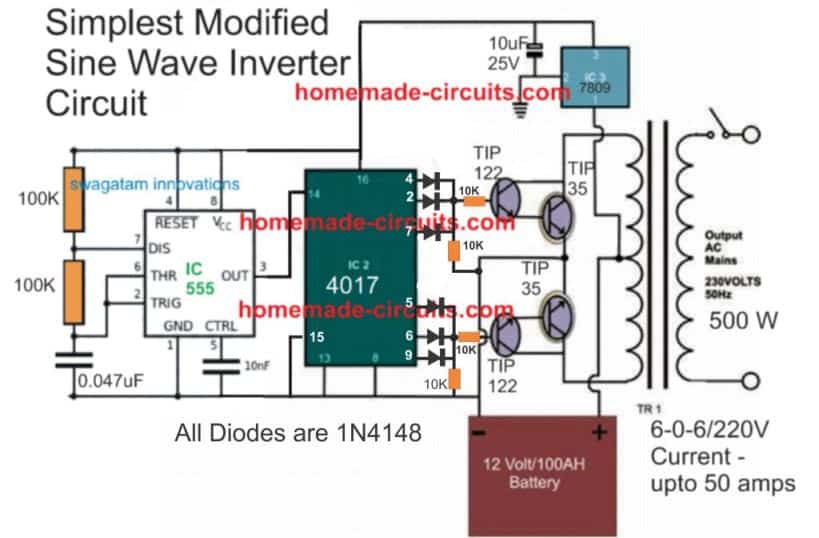
Thank u sir u r my teacher, I will try ths next week. I have a ups transformer 6-0-6 with a battery 32ah. Hope am gona get 220ac output
You are welcome Morris, wish you all the best!
Yes my lecturer,Swagatam! How are you? Can I use ths circuit now with 24-0-24 or 18-0-18 transformer adding a 12v regulator to feed the oscillator? Thanks in advance!
Yes you can use the mentioned transformer with the 4017 circuit.
Swagatam. How r u? I have two 12ah lead acid battery which I want to use with this circuit u referred to me as best in my workshop. My question is that can I replace the transistors with mosfet in that Same connection? Two, is it possible using a 18-0-18 transformer with the two batteries to get 24 volts and work efficiently?
Hi Morris, yes all that you have mentioned are possible.
Just make sure to add diodes between center tap and the outer terminals of the transformer to safeguard the mosfets from damage
So if I want to use irfan44 four pieces, I jst connect them the same way the four TIP transistors are connected?
Yes that’s correct…
Adding diodes between the CENTRE tap and the outer terminals means that all positives of the diodes to point CENTRE tap wire and negative sides to be wired to the outer terminal of the transformer? Thanks
That’s right, the cathodes will go the center tap.
Yes sir, do u have any best modified sine wave inverter charger for 24v to use in my shop so that whn the main is available it charges the battery and whn the power goes off inverter picks on in the absence of the main? Pliz guide!
The second schematic from the following article is probably the bets and the easiest design you can get.
https://www.homemade-circuits.com/modified-sine-wave-inverter-circuit-2/
for converting it into an UPS, you can implement the following concept with the above circuit:
https://www.homemade-circuits.com/how-to-convert-inverter-to-ups/
Thanks sir but do u have modified sine wave inverter charger?
The sine wave has nothing to do with the charger….you can use any battery charger depending on the battery specs.
And which type of mosfet do u recommend sir for that efficient charging! Irf3205 or which one? Thanks
Yes it can be used!
Hey there. I have a high capacity usb battery bank, it’s made up of lithium iron phosphate cells, great unit for powering usb devices. However the ac output is modified sine, which I have read will damage appliances. I am in U.K. by the way. Can I use this circuit to covert to sine wave?
Hi, yes definitely you can use the above concept. However the best way to convert your modified sine wave to reasonably good sine wave is by adding a 5uF/400V capacitor across the transformer AC output.
you can also try making the following from the scratch
https://www.homemade-circuits.com/1500-watt-pwm-sinewave-inverter-circuit/
I have couple of squarewave inverters replaced with Luminous UPS. now they are redundant and kept like scrape material But I want them to convert into sqarewave OR Solar inverter.
Hello sir ,
Thank you so much,
In the above diagram,the two diodes appear to be blocking the signal from the lm321 .What do you think?.
Hello Patrick, the op amp is used for sinking current not for sourcing current….so it is the 0V switching periods which is relevant, not the positive switching!
You can modify a square wave inverter by driving the square wave oscillator with a sine wave IC oscillation driver or by modifying the output of the square wave inverter with a 105J 650V Cap to the output transformer.
Hello,
square-wave can use transistor for the output stage, modify-square-wave can also use transistor too for the output stage, how about pure sine wave? can it also use transistor for the output stage? do you have pure sine wave diagram ? thanks a lot.
Hello, it is possible but will create lot of heat on the transistor, here’s an example
https://www.homemade-circuits.com/make-this-1kva-1000-watts-pure-sine/
Pls sir what is the best frequency i can use for the lower PWM AMV stage
you can try 350 Hz
which filter can i connect to the transformer output for filtration and can i use this inverter for powering LED TVs
you can connect a 2uF/400V across the output of the transformer, you can use it with any electronic gadget after verifying the sine output on scope
Nice one, a 2uf 400V or 105J 400 – 650V
Sir swagatam,can the above spwm circuit power heavy loads like a refrigerator,tube lights and induction motors? Can I use it to construct a 5000w inverter, please advise.
Evans, I would recommend the following circuit instead:
1500 watt PWM Sinewave Inverter Circuit
use 10 to 15 MOSFETs in parallel for each channel, and use a 6000 watt transformer
Thanks very much for your response and help
Dear Swagatam,
# Question-1
I found that my 12 volt single battery UPS system using a transformer which secondary coil is 6-0-6 volt.
Then I open my 24 volt two battery UPS system and I found here using a transformer which is 12-0-12 volt secondary coil. I am confused about this matter because normally we found 12 volt inverter system using 12-0-12 volt secondary coil transformer and if it is 24 volt system then using 24-0-24 volt transformer.
# Ouestion-2:
I tried to convert my 24 volt UPS system to a 12 volt system by changing the transformer’s all coil VAC value (except primary coil) by converting with half value of existing system. But I am not able to do this because the UPS system not work, problem is the UPS system not go to backup mode when main/grid line off. It seems to me I have also change the circuit board some parts but where I change I do not know.
Good night sweet dreams.
Hello Md. Zahirul,
If the inverter is PWM controlled or a SPWM controlled, then the transformer primary value will be normally much lower than the battery voltage. But for a flat square wave design the two values can be similar.
Answering the second question can be difficult without checking the entire working specification of the design.
Thanks very much for your quick reply.
One more question is-
I want to use my computer 1000VA UPS as a my home UPS by replacing bigger battery and adding extra automatic battery charger. Normally we know that computer UPS can backup for small time like 15-20 minute. My question is here any other arrangement needed or not in circuit board for long backup? why not when I use it for my home backup it must be capable to take long backup period,
To increase back up you can add more number batteries in parallel, but the load must not increase. Also the additional batteries will need to be charged from an external charger. Any other changes will not be required.
Thanks Swagatam for your opinion.
Dear Swagatam,
How are you? After a long time come back to you.
I have been made my home UPS about 600VA. My UPS output voltage is 230 volt (280 volt transformer primary coil is connected for output voltage). Frequency is 50 Hz. But problem is when I connect load like one table fan then output voltage decrease to 200 volt. If I connect more load then decrease the output voltage more.
My UPS specification is-
1. Centre Tap Transformer(500 watt) which secondary coil is 13-0-13 & primary coil is 0-180-220-
260-280 volt
2. Using total 6 (3 pic in each channel) MOSFET which number is CS150N03
3. UPS input voltage is 12 volt DC.
Question-1
Now how can solve this problem or how can increase my UPS watt or output voltage?
Question-2
What should be the secondary coil voltage of transformer for 12 volt input system inverter/UPS?
It is 12-0-12 or 9-0-9 or 15-0-15
Question-3
Give me some high watt MOSFET number
Dear Md, the transformer voltage rating will depend on the oscillator circuit specifications…Depending on the PWM duty cycle of the oscillator, the transformer voltage rating could anywhere between 6-0-6V and 9-0-9V, but it cannot be 12-0-12V or higher with a 12V battery. If there’s no PWM involved then you can probably use a 9-0-9V transformer.
The MOSFeT number mentioned looks OK for the application.
However, the battery Ah must be at least 5 times higher than the load current.
Sir, do you know much about Fuelless Generator? To generate a steady electricity with a 12V DC motor and a permanent magnet alternator with a feedback charging system to the 12V battery.
Hi Don, Presently I do not have this circuit, if I happen to find one, will surely let you know!
Dear Swagatam,
You says “the transformer voltage rating will depend on the oscillator circuit specifications, and depending on the PWM duty cycle of the oscillator”
Please describe for understanding
Hello Md, you can get the complete explanation under the following article:
https://www.homemade-circuits.com/inverter-voltage-drop-issue-how-to-solve/
Dear Swagatam
Very very thanks to you for your quick repose.
Now I want to learn about PWM voltage
My questionnaires is:-
1. How PWM voltage works in inverter?
2. If my main transformer primary voltage is 12-0-12 then how much PWM voltage needed? 12 volt or 15 volt?
3. Can I take PWM voltage in seperate transformer instead of main transformer?
4. Can I connect seperate auto charging circuit in my home UPS? why not I don’t want to heating my main transformer by charging purpose.
Gentally waiting for your response.
Hello Md,
To learn how to match PWM with transformer rating, you can read the following article.
https://www.homemade-circuits.com/inverter-voltage-drop-issue-how-to-solve/
PWM is nothing but switching the transformer winding with a certain ON/OFF rate or duty cycle so that the output RMS is correctly set.
PWM is given to main transformer only.
You can use a separate transformer for charging without any issues
Dear Swagatam you said
“PWM is nothing but switching the transformer winding with a certain ON/OFF rate or duty cycle so that the output RMS is correctly set.” It’s ok but we know that switching the transformer winding done by the MOSFET functioning. Please describe in details.
“Can use a separate transformer for charging without any issue”. Fine, but then both the charger (Internal charging unit in UPS circuit board & external charger) will charge the battery or not?
I have seen some inverter board without PWM specification like “NATASHA” inverter board which is made in India. How this type of inverter works without PWM voltage?
What is the advantage of using PWM in an inverter?
Dear Zahirul, your questions cannot be explained in comments, you will have to learn the whole concept of MOSFET switching and PWM switching from the beginning, to grasp the whole working.
Dear Swagatam,
For winding UPS/IPS transformer which wire we have to winding first?
Thick wire (primary coil) or thin wire (secondary coil)?
Is there any differences for winding firstly or lastly between thick or thin wire.
Hi Zahirul, You will have to wind the high voltage winding first, and then apply the low voltage winding after a layer of insulation tape.
Thank you sir for the spwm description.Now if i put the upper astable at 50hz,what will be the freq of the lower astable,50hz?.How can i attach a feedback loop to the circuit.
Thanks.
Hi Patrick The lower astable must be 4 times more frequency than the upper astable, feedback loop can be attached using this concept:
https://www.homemade-circuits.com/load-independentoutput-corrected/
Hello sir swagatam,will the part list change if was to use a0-18v transformer and 24v battery?
Parts will be the same, but the C1, C2 may need some change until the right frequency is achieved.
How I can find sin wave from my home use IPS; 800KVA, 220V, (square wave output)
I love your professional sincererity and openness which is the key to personal knowledge development for all humanity. You share openly to the entire universe what costed you sweats to achieve. They say ‘SREVICE TO MAN IS WORSHIP TO GOD’. All of us in the electronic field will forever shower gratitude to a great gem like you.
Chibueze Nwakpuda
Thank you Chibueze, Appreciate your thoughts very much!
Can not perfect trafo design affect the waveform.
hello mr Swag,
I found your site from Google. A lot of stuff here, it is very good!
I know that the Square Waveform inverter needs a classical iron (50hz) transformer to work.
I have a dumb question.. do a spwm inverter (which pwm frequency is for example 1 khz) also need
a classical iron transformer OR it needs a ferrite toroid transformer.
I am confused because of the pwm’s high (ralative to 50hz) frequency.
thank you mister!
Petros Chris
thanks Petros, you may be right, 1 kHz could cause problems for an iron core trafo, in that case you can reduce it to around 200Hz or 300Hz
thank you sir for your quick reply.
i want a design of a modified sine wave inverter in matlab simulink
Thank you very much Sir for the thump’s up and for replying me. The issue is that am using a stabilizer container to cover the inverter…thus it wount contain upto 24(12pairs) of IRFP150N because the Vero Board will be too long. I learnt there are higher IRFP MOSFETs, but i dont know the numbers and how many watts they dispense that give 3kva with lesser pairs.
Hi Steve, no need of ding 12 pairs of mosfets, if you use 24V as the supply, just 3 mosfets on each channel will be enough..
Ok sir, but 3 MOSFET of IRFP150N will only give me 750watts. I need the specification of 3or4 pairs of MOSFET that can give me upto 3kva, please Sir.
Steve, if you intend to use the mosfets without heatsink then it will 250 watts each…but with heatsinks, they will be 40 x 24 = 960 watts each according to me.
Used two pair RU190N80 in each Chanel and it can handle up to 5kva load
Good morning Sir, ive successfuly built a 1000w inverter with a 24-0-24 to 240v transformer, using a 4pair IRFP150N MOSFET for the Power Stage and its working well. I need to build another 3000w inverter but if i use the IRFP150N MOSFET it will be too long and ridiculus, so please which MOSFET can i use that will make it easy? Thank you Sir
That’s great Steve, appreciate your efforts.
you can use IRFP150N mosfet for achieving 3kva, without any problems, it won’t be an overkill..
if possible please send me a small video clip of the working inverter which you have made to my email…I’ll be grateful!!
my email is homemadecircuits @ gmail.com
Hello sir, i asked some questions in one of ur post and i see no reply, let me ask u the same questions here:
1. In choosing or selecting MOSFETs, what must i consider, is it the volt or the amp of the MOSFETs?
2. Can i use stabilizer transformer to connect with my inverter circuit?, or does a stabilizer and inverter has different pattern of winding
I have already answered them under the other post
Sir I hv some questions-
1. instance of ( R1,R2,R3,R4,R5,R6,T1,T2,C1,C2 the 50Hz oscillator circuit)
can I use a 4047 oscillator with 50-60Hz?
2. instance of (R7,R8,R9,R10,C3,C4,T5,T6,VR1 the pwm circuit) can I use a 555 PWM circuit?
3. I want to make 4047 for oscillator, with 50-60Hz and then can integrate 555 PWM with it as like as u shown the 2nd circuit, is it possible?
4. if possible then what ll be 555 PWM frequency?
sir plz make me understand
Thank u
Mehedi,
yes It is possible, a few of my other designs have already used the same principle which you are referring to.
So of it is possible then what will 555 PWM frequency at pin 3 of 555? plz make it clear
frequency can be anything between 400Hz and 700Hz, but the PWM must be set correctly to get proper output
ok I understand bt can u give me any suggestion for proper 555 PWM circuit? one more thing can I drive 555 ic directly from 12volt 9amp battery? is it need to any regulator for 555 ic, if need then what volt regulator need?
you can use the 555 section from this article
https://www.homemade-circuits.com/infra-red-ir-led-flood-light-circuit/
if your 12V is constant then 9amp will not matter, you can use it for the 555 circuit.
Is the second diagram is a pure sine wave or modified sinewave inverter
no it is not pure sine but it is an improved modified sine
Can I expect same sine wave output if I connect 555 pwm with the first square wave circuit?
where exactly do you intend to connect??
Maybe a laptop adapter
I was referring to the following statement, could not understand this:
“…if I connect 555 pwm with the first square wave circuit?”
The first circuit with two bc547 and two MOSFETs
yes it is actually possible! you can hook it up directly with the gates of the mosfets.
Sir please help me to convey the details regarding the conversion of 12 volt 50 hz square wave signal to 12 volt 50 hz sinusoidal wave…pls help me in the designing part ,
Afsal, you can achieve it through a suitably dimensioned L/C integrator circuit.
I know that when using only n channel mosfet for full bridge inverter the mosfets on the high side must be higher than the voltage applied to the drain. How can that be achieved? Can I parallel them for more power instead of using one set of mosfet for switching?
paralleling will increase the wattage handling capacity, it won’t help the bootstrapping implementation.
Hi Swagatam Sir
I implemented one of your CD4047 circuit and I’m having a good square wave at the output
But I want to make it a square wave to be suitable for all appliances
I tried to use three pole RC as filter but it doesn’t really work
I tried a low pass filter but only one of the two waves is giving a trapezoidal pattern
I want to try a bandpass filter but I don’t know which OpAmp to use
Can you please give me a link to a circuit of any filter that you believe will work perfect or even a complete Sine wave circuit
Thanks for always being there Sir
Hi Sodiq, the RC filter shown in the last circuit is a square wave to triangle wave converter, and it is a proven design, and therefore it has to work. Please check the RC stage separately using different frequencies and try adjusting the RC part values by some trial and error until you get the desired triangle waveform.
Sir I am Nataneil a new person on your site. I am seeking help to build a 24v input fullbridge inverter. I have only irfz46n n channel mosfets for the high side and low side, a cd4017 ice, lm555 timer ice. I need to know how do I increase the voltage for the high side and to how much voltage.
Hi Nataneil, you can increase the voltage by configuring the IC 555 output with a voltage doubler stage….if possible I’ll try to include it as a new post in my website soon, alternatively you can try implementing the concept which is explained in this article:
https://www.homemade-circuits.com/2017/03/sg3525-full-bridge-inverter-circuit.html
but since this concept is researched from various online sources I cannot guarantee its working.
for a foolproof results, you can perhaps go with a specialized design as given below using IC.
https://www.homemade-circuits.com/2014/01/simplest-full-bridge-inverter-circuit.html
Hi sir, I'm now double stressed, I, this time recently checked only the square wave part of circuit with my old 12-0-12 5amp transformer and this time I got 266v even without pwm, I really think that the circuit and 555pwm have damaged both of transformer now what to do? This time life sucks ?.
Hi sir, every thing else is going good now but the LEDs are still fusing because of high voltage 260v(without load) as you know with loads it's 230v in mine case (refer to upper comments) and I can't use 9-0-9 transformer because I had bought 12-0-12 10A far earlier, and the voltage problem is also due to that reason I know. So what to do now? Can I use a converter shown in your blog (anyone from your blog) for 12v to 15v? Is it safe I'm positive towards this regard, please read full and reply soon.
Hi Aabhishek, to control high voltage you can add the following circuit to your inverter and see if it helps.
https://www.homemade-circuits.com/2014/01/automatic-output-voltage-regulator.html
Hi sir, could you please help me with some other idea with this matter. Read older comments for revising summary of problem. Please let me know if you have any help for me
I'm using 12-0-12 10A as I couldn't buy a new 9-0-9
there's no other idea, either you use the 741 circuit which is suggested to regulate the output, or change the trafo.
or alternatively you can buy another 12V battery and put in series with your present battery to get 24V and use this 24V with your 12V trafo…then adjust the PWM to get 240V at the output
Hi sir ???new problem arised, today I checked my circuit without pwm(only square wave circuit) and multimeter was showing 595v to 600v output and then by connecting pwm I tried it to adjust then it showed "1" means limit crossed. Earlier this problem was not there why is it happening even without pwm, and also with pwm. This problem happened only today, please tell me what is wrong now. I'm littrally very stressed ?, this was my holiday project and holidays are going to be over.
??☹️my electronics role modal please help me. Please.
Hi Abhishek,
make sure the PWM frequency is not over 200 or 300Hz.
for your 600V issue you can read the following article.
https://www.homemade-circuits.com/2017/07/inverter-voltage-drop-issue-how-to-solve.html
and please don't comment under this article because it is flooded with comments and I have to press "load more" button repeatedly…you can comment under some other inverter article
Sorry sir, I'm commenting again here but sir firstly I tested it without pwm then I tested the same transformer with my another square wave inverter then output was 360v. And I think this setup have damaged both of my transformer as I tested old 5amp transformer 12v then also the output was 260v, because earlier I had tried both of my transformer with this setup using pwm also and I think my both transformer are now damaged due to this full set (may be high frequency done this damage) please help, and can we have a video call so I can make you understand more easily.
Hi sir, my transformer is of good quality it's made by shopkeeper on order its big and weighs 8kgs, sir yesterday I added new mosfets and increased them in parallel but when tested no output was there (fluctuations) only some stabilizer like abnormal sound comming when I removed then also conditions were same,I'm very stressed.I think may I'm these problems are because I'm using zero pcb (pcb with square boxes and predefined holes) and not the copper claded, and also due to some improper soldering, because transformer is good. I have written thanks because everytime you give true knowledge and guidance. PLEASE reply soon.
Hi Abhishek,
if transformer is good then it should take the load. and the voltage should not drop…. I am sure something is not correct in your circuit or the parts which I cannot identify from here.
adding mosfets will not help at all, because it's not correct ,a single pair of IRF540 can handle upto 200 watts to 500watss easily.
try with BJTs if you are not able to use mosfets…try with TIP142 instead of the mosfets
Hi sir, can you please tell me how much watts power a samsung 32inch led tv consumes?
I have no idea about it, you may find it behind the TV
Hi sir I have replaced the lower pwm with 555pwm as you advised and it's good. I have adjusted it without load on 240v but when I connect 3 Watt incandescent bulb the output dropped the voltage by multimeter was 178.so how to adjust it whether while adjusting I have to also connect a load then the voltage without load must come upto near 300v what to do master.
Hi Aabhishek, since this is a simple circuit and does not employ any load control circuit, therefore the best way to adjust the PWM is by connecting the load, and anyway the voltage which you may see in your meter without load may not be correct, because the meter will always show a much higher voltage without load due to its high impedance nature, therefore the best way is to adjust the preset with a load connected, and remember I had told you to use a 9-0-9 trafo, at 10 amps and a 12V 7 to 10AH battery fully charged.
Hi sir, now I can power mobile charger and 3w bulb (tested) on inverter but when I connect 7w LED bulb the bulb is not glowing and frequency sound increases.what to do sir?
Aabhishek, something is not correct in your circuit, it seems the trafo is not saturating correctly, and this can happen when either the transformer or the battery or both are not matching correctly.
when you connect ammeter in series with the battery the meter should show a current equivalent to the load current.
Hi sir I think led bulb might be fused due to high voltage 260v ac, when i connect 3w bulb the voltage goes to 230v and when connecting my phone charger then voltage drops to 215 v what to do? Is there any way you can suggest so I could use this inverter as a good inverter with no further problems or issues. PLEASE HELP. So finally I can say you thanks for this project.
Hi Aabhishek, LED bulb are rated to work with 285V so it cannot fuse at 260V.
Your transformer is not taking the load due to lack of amps, change the transformer with a good quality heavy duty transformer…in todays market most transformers are falsely labelled…for example 3 amp trafo can be seen labelled as 5 amp…no need of saying thanks
Hi swagatam sir, is it possible adding mosfet in parallel with reducing the chances of MOSFET damage and also reduces mosfets heat?
You must first find out why your mosfets are burning if it's due to overloading then you can you can add parallel mosfets, but I don't think it's due to overloading.
I hope you are my following my suggestions and not doing just anything haphazardly???
Hi sir, I want to ask that is it possible that while adjusting preset the mosfets can damage. https://plus.google.com/+AbhishekSharmatechperson/posts/9PNR5Rfx2Rm this is image link for pwm circuit.
No that's not possible, in your mosfets can get damaged due to a duplicate mosfet, static electricity from your hands, wrong pin connection, drain short circuit or perhaps from reverse transformer emf if diodes are not connected
Hi sir, today I checked the circuit without pwm it was working good without pwm but now I used it with pwm then for some seconds voltage was upto 175v and then without adjusting it reached 201v and mosfets were hot (heat sink is used) and smoke was comming. PLEASE HELP. https://plus.google.com/+AbhishekSharmatechperson/posts/AndSBSBEkVh link for modified circuit as I'm not using bc547 and 557 STAGES.
Hi Abhishek, the buffer stage BC547/BC557 was specifically introduced to keep the mosfets safe, but since you were having difficulty in configuring them therefore I allowed you to try without it…but I think it should be included, so better put it back in place as shown in the diagram, I'll update the diagram soon and make the stage simpler by removing the extra diode at the emitter of the BC547.
And remember you shoold NOT make the design on a breadboard…use a strip-board and make it by soldering…
Hi sir.,ok I will do it again and I'm using zero pcb and always solder, no breadboards!. Hope doing this will help, sir I really respect you and your knowledge you are like my favourite teacher.
Sir in my PCB there is no space to put those bc547 and 557 STAGES, so what to do I really want to make this inverter Perfectly working. PLEASE HELP ME sir.
Thanks Abhishek, how can I help you if there's no space in your PCB??
replace the lower oscillator with a IC 555 PWM oscillator as shown below
" rel="nofollow ugc">
connect the output pin#3 with the PWM diodes associated with the mosfet gates
Hi swagatam sir again problem even with the modified version of this inverter (see last comment) which you approved when I removed mosfets it was giving 300v output without using pwm circuit but the transistors in first oscillator were becoming hot so you suggest me an alternative, and I have changed mosfets 2 times from starting day and till now. Working without mosfets. Im using 12-0-12 10A transformer and 7.6ah battery. See last conversation for circuit and tell me an alternative this is first time I'm having problems in making something. I'm using 12-0-12 10A transformer.
Hi Abhishek, this is such an easy circuit, not sure why you are getting so much of problems, may be because you are doing it without understanding the concept, or using damaged parts.
By the way who told to remove mosfets??? how can you drive the transformer without the mosfets??
I am not able to understand what exactly you are doing….
I would advise that you first thoroughly understand the working of the two circuits and all the parts and only then proceed.
Hi sir,
Can I use transistor Darlington pairs instead, of irf540. May be the seller from whom I take irf540 has given damaged mosfets.
Hi Aabhishek, yes you can definitely do that, that's what I had recommended you earlier…..you can use 2N2222 and 2N3055 in darlington mode…or any other similar combination will do
https://plus.google.com/+AbhishekSharmatechperson/posts/RH3rnQjRYLm please check the circuit in link, I have less time.
Please sir reply fast, check this link circuit
https://plus.google.com/+AbhishekSharmatechperson/posts/RH3rnQjRYLm
abhishek, I have already answered you…your diagram is incorrect…you must use two separate diodes from the gates just like you did in your previous BJT based circuit.
I hope you have understand this time.
Hi sir, I made new circuit, you may please see this and suggest
https://plus.google.com/+AbhishekSharmatechperson/posts/RbQWxq8bZoD
PWM diode is correct, however the 1K and the 1n4148 can be removed…you can directly connect the gates with the cpllector of the transistor
Hi sir, I think you haven't focused on my question, I WAS ASKING " can I make this modified sine wave inverter by not using the upper bc557 and bc547 stages, diodes and all, by using the main upper AMV and lower pwm, and mosfets, no bc557 and bc547 stages , as these things are creating complications." * I MEAN IF I REMOVED THE BC547 AND 557 STAGES AND JUST USING UPPER (MAIN AMV) AND LOWER PWM AND MOSFETS ONLY. PLEASE REPLY FAST TILL AFTERNOON PLEASE MO ?.
that is what I exactly suggested…use the first circuit in the above article which has used only mosfets no BJTs….you can integrate the PWM directly to the gates of the mosfets
Hi sir, how to connect, I mean only one side of pwm output is connected to only one MOSFET gate, if it's not clear please check link https://plus.google.com/+AbhishekSharmatechperson/posts/RH3rnQjRYLm
Abhishek, do exactly as you did in your previous circuit…using two diodes, it is so simple.
Hi sir, when I test pwm, with 16v supply separately, it's out put is 6v,ac,and the output can only be measured when I connect only one prob of multimeter to the capacitor output , when I connect both probes output on screen is 0v, is this normal,?
Another question is that only lower circuit is said to be pwm or the upper bc 547 and 557 and 1n4007 circuit also a part of pwm
Abhishek, your method is incorrect. You must connect the meter probes across the collector/emitter of the transistor…and the meter should be in the DC range NOT AC range. and the measured volatge must vary from some minimum value to maximum value in response to the pot rotation.
The Bc547/557 is not in the PWM section.
you can try the first circuit from this article…connect the LEDs and see the effect of the PWM on the LEDs..if it illuminates from fast to slow and vice versa then the circuit working OK.
after this you can reduce the capacitors to 1uF for fast PWM..
https://www.homemade-circuits.com/2012/01/how-to-make-any-light-strobe-light.html
Hi sir, one question can I make this modified sine wave inverter by not using the upper bc557 and bc547 stages, diodes and all, by using the main upper AMV and lower pwm, and mosfets, no bc557 and bc547 stages , as these things are created complications. Please reply as as possible.
You can try it as shown in the first diagram, make sure to use 1K for the gate resistors and put 1N4148 diodes parallel with these resistors in the following manner:
1.bp.blogspot.com/-IJ69-6jHAI8/UjGwaj9sxVI/AAAAAAAAFOY/vdqUBesdFqA/s1600/how+to+prevent+mosfet+from+burning.png
Hi sir, yesterday night I tested my above circuit by 12v battery for adjusting the 50k preset with multimeter connected at output of transformer, so in first round the voltage was going on decreasing from 210 to 90v ac, In 2nd round the output was 250v and suddenly the point where I had connected the negative terminal catches sparking and fuse burnt,so I removed and again connected battery negative (to point where pwm -ve, oscillator-ve and both sources of MOSFET were connected together) but again that point shorted sparked. I'm using pcb (not printed one), can you assume what is problem or which part should I check. Please help me
Abhishek, sparks should never come,,,it means there's a short-circuit in your circuit or something is not working correctly.
first make the basic circuit without the PWM….and make sure it produces 250 to 300V and is able to illuminate a 60 watt bulb very brightly.
after this check the PWM circuit with a DC voltmeter connected across collector/emitter of any one of the transistors…the Dc V must change as you vary the 50 pot. also confirm the frequency of the PWM with a frequency meter.
If you are having problems with a transistor oscillator you can replace it with a IC555 PWM circuit which is much easier to adjust
Hi sir, I removed the second AMV circuit and checked everything in first upper circuits for shortings using multimeter I found in one MOSFET source and drain of that mosfet beeped, while in other this was not happening, so I think shortings of source and drain shows that mosfet is faulty, so replacement of one MOSFET will be OK or I replace both, how to protect new mosfets from further defects. Please reply fast. I'm really interested in making this inverter perfectly working.
You can refer to the following article for learning how to protect mosfets
https://www.homemade-circuits.com/2013/09/mosfet-protection-basics-explained-is.html
if your mosfets are duplicate then cit cannot be protected.
you can replace them with BJTs if you are unable handle mosfets
Hi sir the link you sent is seen and understood but I want to ask that after replacing MOSFET, now can I check the inverter or I need to give some protection to the mosfets, which diodes can I use with mosfet to protect them. Can I test inverter without providing any diode protection to mosfets.
Abhishek, although all mosfets are protected internally with diodes, still you can place diodes across the primary of the trafo… from center tap to the outer taps..cathode will go to the center tap, and anode to the outer taps…you will need two diodes from ceter to the outer taps.
1N4007 diodes can be used for the diodes.
Hi sir, every time you are so helpful, I want to ask that can you explain the procedure for adjusting preset (50k I have used) without damaging any thing. PLEASE HELP ME, tell me a safe method. How to adjust it.
Hi Abhishek, the procedure is simple.
initially keep the preset slider at the center.
Now switch ON the inverter and connect an AC voltmeter at the output of the transformer for measuring the voltage.
after this slowly adjust the preset until the output voltage settles down to 220V.
I hope you have used a lower rated 6-0-6V or 9-0-9V trafo for a 12V battery
Hi sir, I'm using 12-0-12 10A,transformer for 12v 7.6ah battery. Is it OK? Will the circuit work perfectly. OR any correction I should make. PLEASE REPLY FAST.
12-0-12 will produce 180V output with PWM activated…you will have to use a 6-0-6 10 amp or 9-0-9 10 amp trafo for getting proper results
Hi sir, I only have 12-0-12 10A transformer, you must have specified in article that it's necessary (mandatory) to use 9-0-9 v transformer this is very disappointing.Now the problem is budget and I already spent rs 1050 on that transformer, shopkeeper will also not take that back because it was made on order, can you please tell me a solution so I could get 220v to 230v AC from the same transformer i.e 12-0-12, should I increase input if yes, how? Please help, I couldn't ask my parents for this. PLEASE HELP.
Hi sir, please reply fast,can I use 820pf capacitor instead of 680pf, and 50k preset instead of 47k in second circuit, because 680pf capacitor are not available in market. And tell me how to adjust the preset and from where to measure the rms to adjust preset, explain me whole process please. PLEASE HELP ME.
Hi sir, I'm using 50k preset (not the potentiometer) and 820pf capacitor instead of 680pf capacitor, is it OK? How to adjust the preset, what is the process.
Hi Abhishek, yes those are OK will do!
for confirming the frequency you can take the help of the following software
https://www.homemade-circuits.com/p/transistor-astable-multibivrator-amv.html
Hi sir,
Can you tell me how to connect preset in this as the circuit shows,all three terminals are connected at different places, I don't know how to connect, can you please assist me through any image or photo explanation, please reply fast.
Hi Abhishek, the arrow symbol indicates the center pin of the preset and the outer two points correspond to the outer two pins of the preset…
hi sir,
please tell me how to tell shopekeeper if want transformer for 100 to 150 watts inverter? ,as if i say them i want 12-0-12 10A transformer they say tell us "va" .thay dont understand me,tell me what should i say them in their language if i wat transormer for 150w inverter ?
Hi Abhishek, If they are asking for VA, then tell them the value by multiplying 12 x 10 = 120 watts….. there's nothing too critical about it….
Abhishek, those are not Darlington pairs, those are arranged to generate a push pull action on the mosfet gates…they are in NPN/PNP formation
hi swagatam sir ,can you elaborate about circuit shown in link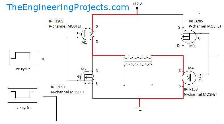 and 1.from where should i take output
" rel="nofollow ugc">
2.what kind of transformer is used.
Hi Abhishek, you can feed the mosfet ends with any push pull frequency source such a from a 4047 IC, a SG3525 IC or IC 4017 etc
Hi sir what is the value of the transformer used (in amperes) in the link and can I replace all mosfets with irf540. And can I use centertap instead?
" rel="nofollow ugc">
the trafo value will depend on your choice of output voltage and current and also the battery specs, just as we do for push pull inverters.
center tap cannot be used, for center tap you won't require a H-bridge circuit you can simply use a 4047 type IC for it
Please Sir, How Can I make the the Frequency Of this Circuit Variable?
By changing R1/R2
Thanks for posting such a nice and useful project.
I want to make an inverter of 1000-Watts or higher, could please guide me what components mainly required
Best Regard
I have already posted a related circuit in this website, please use the search box to find it.
Sir, I have already built this inverter. But, It is sometime giving above 230v output, depend on the battery AH I use.
Colud you help me with any output filter, so that the out will be constant at 220v to 230v?
Thanks
Aminu, it is not required as long as the output is between 210V and 240V, it is quite normal.
If you add an output regulator it will make your design unnecessarily complicated
Hi there, I have read over your blogs and am very impressed with your electronic knowledge, I have a question for you, I will be running two dc to ac inverters rated at 10,000 watts surge and 5,000 watts constant running watts each. They are however MSW ( modified sine wave) I am wondering if there is a circuit I could build for each of these that could convert them more closely to a standard sine wave to make them safer for use for sensitive electronics ETC, computers, tv,s video games and the like? I am familiar with basic and communication electronics but rather weak when it comes to inverter modifications. the inverters are a HF( Harbor Freight) product that carry the CEN-TECH brand name. I havent been able as of yet to find a schematic for these units. It would be greatly appreciated for any help you could offer…thank you in advance
Mad Scientist
Thanks Eric, It is definitely possible using the concept explained in the above article, however first you will have to figure out how the mosfet stages are configured in your existing inverter, and then target the right mosfets for integrating the explained circuit theory…otherwise you may end up ruining the entire inverter or create catastrophic results.
You can also try a much improved version using SPWM which I may soon present in one of my future articles in detail. In the meantime if you need any help you can feel free to consult me
Sir can we convert 230v square in to 230v sine wave directly please help me out
you can convert 330V square wave into 220V sine wave using SPWM,
Good day sir, the VR has two legs or three legs. Bcos the one i have is three legs but the one on diagram is just end to end with the transistors. Thanks
all presets and pots will have 3 legs
what is freq of oscillator?how to calculate?
Yes Sir, it has.
But what I mean is this, UPS works on little corrent battery i.e 7ah and it's able to operate a computer that needs high watts ?while majority of inverters cannot.
I learn this due to the suggestion you made to start our homemade inverter with big ah battery ? e.g 100ah or 200ah to operate 100 watts which is not as big as deck top.
thanks you Sir.
your assumption is not correct, an inverter can be equally efficient just like an UPS as far load handling is concerned…except the waveform and automatic functions which are the more enhanced in UPS.
please show me where did I say that a 100 watt load would require a 100 AH battery??
A 100 AH battery will be required for a 100 watt load if a back up of 10 hours is expected….so I might have said on that context.
Sir this is Aminu.
Sir I wonder why UPS can operate computer ? using a 12v 7ah battery ? while inverter cannot work with such a higher watts device on 12v 7ah.
Aminu, an UPS also has a built-in inverter so that's a wrong assumption.
without an inverter the UPS cannot create the back up supply
Hi friend I like your projects. I actually want to build and try your design. So, for the first circuit in which you used two power mosfet , can i replace them with IRF150n? If so, what will be the output power. And also kindly tell me if i use IRF150n with the second schematic contains four transistor what will be the power then? Thanks. You always helped me alot.
Thank friend, the output will depend on the wattage rating of the transformer and the battery AH capacity…the mosfets rating should be selected such that they are able to comfortably handle the power consumed by the transformer and the connected load.
only the mosfets are responsible for power delivery, other transistors are only for buffering they need not be changed
Sir
I have su-kam inverter trusty . 1500 w . 24 v .when connecting to home all fans making noize . What should i do to remove that noize from fans . Shall i add capcitor to the out put . If yes which type and size
Thanks
yes you can try it…..you can see the following example design and follow the configuration:
4.bp.blogspot.com/-khKat0UA8Jw/UITpCnNd7yI/AAAAAAAAA_A/8x-KAD2aHLE/s1600/simplest60+Hz+Inverter+circuit+diagram.jpg
I would like to know if this circuit has been implemented and tested as i am experincing some problems and would like to brain storm for possible rectifications from those who have implemented this exact circuit.
Sir what I mean is that, If I used the 2nd circiut the fan is not operating but the circuit can operate many appl and If I remove PMW part and leave AMV and BC547/557 the result is the same. whhile with the first circuit (squar wave) that has no bc547/557 stage, the fan can work with little noise.
Aminu,
connect a 60 watt incandescent lamp to the inveter output and check its brightness with PWM ON, and without PWM, this will tell you whether or not PWM is reducing the output power?… and why the fan may be finding it harder to rotate with the PWM ON.
Sir,
I did it.
I used this ic555 configuration, as you suggested me alias.
http://www.www.homemade-circuits.com/2012/05/making-adjustable-electromagnet-circuit.html?m=1
After I connect this to the AMV, I can vary the volt from 0. to 220v and above.
I dont realy know if, my circuit is faulty or not.
I tried many electronic app and they work, But the fan is still incline to operate.
I wondar why, the First circuit (Square wave) can operate the fan with little noise, While if I connect the PWM part (including this newly adopted i.e IC555 part) it woun't operate.
Anyway, Sir, Your help is always appreciated and Iam very much proud of you Sir.
Thank you once again.
Aminu, the PWM is chopping the actual 50 Hz, that means it is actually reducing the overall power….so this in turn means that the transformer needs to be more powerful for a PWM inverter because the PWM is cutting off 50% current…so this could be the issue…try another trafo with higher wattage and check the response.
Ops, Iam wrong Sir.
The volt is not 220-240 its almost 200v peak and almost 195v the low, so, its not stable. It is shaking ups and down within a second.
This is why the multimeter is reading wrongly.
Aminu as long as you don't confirm the lower circuit performance you'll always be in doubt regarding the circuit proceedings, I think you should try replacing the lower AMV with a 555 IC AMV, I'll try to update the modification soon in the article, may be tomorrow, you can then try it out and check the response.
I did it Sir,
But the test is done with 0.2uf i.e 224j instead of the one you suggested, because I have only a pair of 104 which was used in PWM.
Based on this test i can see the volt is ok, Its around 220 to 240 now with PWM but I tried to adjust the pot and nothing change even if the pot turned to the end of each direction.
But I load only 26watts economy ligh bulb.
Ok Sir,
I will try it and update you with the result as soon as possible.
Thank for the help Sir.
Sir,
Right now I do some changes as follows,
I used 7.2_0_7.2 tranfo 650Va.
I chanced mosfet to IRF3205.
I removed pwm.
finaly, the fan operates with some low noise if compared with my last test.
and if I connect pwm part, the fan fails to operate and produce louder noise.
Thank very much, its few staps remain to build a very reliable low cost inverter.
Aminu,
PWM will reduce the RMS of the output voltage therefore the transformer's primary rating should be lower than the battery voltage, 7-0-7V is a good trafo but its current should be at least 10amps, and for higher loads the battery AH should be at least 10 to 20AH fully charged.
If the PWM frequency and duty cycle is high, the fan will make noise, so adjust it until the noise is almost gone.
reduce the lower AMV capacitor values to 0.1uF to reduce the frequency and adjust the pot to optimize the duty cycle, and then see the response.
Sir,
with pwm the AC output volt is between 180v to 111v or even lower, but without pwm the volt is alway above 200v AC.
I used three transfo
1. 7.2-0-7.2 transfor removed from 650va
2. 12-0-12 5A
3. 500va transfor that has no details printed on it.
each showed the same result.
I used 12v 20AH battery.
Sir, The inverter has no any other problem now because I discovered them and solved them today.
But, the issue of operating Fan is still unchanced.
the fan is 50watts and its only producing loud soud without turning, even if I used my hand to help it to turn, it won't.
and this problem is the same with both oper and lower circuit.
Thank you Sir for the help.
Aminu,
remove the PWM feed from the lower circuit, and check the response.
and what's the battery AH?
and what's the transformer amp rating, let me know about these, I'll try to troubleshoot.
would it be possible for you to use power BJTs instead of mosfets just for testing sake? because BJTs are much easier to handle than mosfes.
Sir,
I am refering to this recent one that you asked me to build and I builded it. I dont mean it has problem, Iam the one coursed it.
I found the track and jumper are borning and the mosfets are getting hot instantelly when i load a higher watts. so through your help all those was solved.
base on my check I discovered the courses of the problem as follows: the battery power is set to cross over the circuit then goes to transf and it is also solved through the procedure I sent in the last mail.
Sir, still Iam exeriencing some problems that i dont know their source.
1. one of the mosfet is getting hot If i load the
laptop or any higher wattages appilience like
100watts bulb.
2. my multimeter is ok, but when connected it to
the inverter in order to test the AC output volt, the multimeter is reading wrongly and if connected to main AC its reading normal 220v or 219v.
3. still the inverter can not operate Fan.
As usual, I need your help Sir to solve them
thank you very much sir.
Morning Sir,
The problem of component borning has been solved by following this procedure.
1. I connected the battery positive directely to the centre of transfo and then I used thin copper ware with switch to the positive input of the circuit board.
2. The negative of the battery is also directely connected to the sourse of the two mosfet then I used another thin copper ware to the board.
I think, this can save all the components in the board.
Sir, still Iam exeriencing some problems.
1. one of the mosfet is getting hot If i load the laptop or any higher wattages appilience like 100watts bulb.
2. my multimeter is ok, but when connected it to the inverter in order to test the AC output volt it is reading wrongly and if connected to main AC its reading normal 220v or 219v.
3. Still the inverter can not operate Fan.
As usual, I need your help Sir to solve them
thank you very much sir.
Aminu, which inverter circuit are you referring to?, is it the above inverter or the ready one faulty inverter which you are presently repairing?
if it is the one which you are repairing, it would be difficult for me to judge and troubleshoot because I don't know what kind of circuit may be used in it and what stages may be involved…
and what will be the effects on the same motor load if i was to directly connect it to the output of this inverter ???
thanx for all ur help.
so if the LC filter is added to the circut will i be able to run a 20 watt ac motor load without having the adverse effects on the pump ????
LC will reduce harmonics and will help the motor to run with less noise, less heat and more efficiently
Salut Swagatam..
J'aimerais bien avoir a la sortie de l'onduleur 120 volts.pouvez vous me donner le shema?
Merci.
Salut Wileps,
you simply have to use a transformer having an 120V rated secondary winding, rest everything can be as is
il suffit d'utiliser un transformateur ayant une 120V évalué enroulement secondaire, du repos tout peut être aussi est
Sir can you please suggest me what is wrong?
1) If I connect a load with morethan 100watt the Mosfet are getting hot and even some of the component in the circuit are damaging, like the ware i used for making jumpers and some line in the viroboard.
2) This new Inverter that I build (sinewave) cannot operate fan. I tried it with a table fan, and the fan is only emitting louder sound as if it is going to bust.
In testing this sinewave circuit, I used:
*12v 20A battery.
*Transfomer removed from 500va UPS and,
*IRF3205 mosfet.
Thank you sir.
Aminu,
The PCB is getting hot because the tracks or the jumpers are not able to bear the higher current level, you should use thicker wires and tracks for the PCB, and use a big heatsink for the mosfets.
Adjust the PWM and see which PwM setting produces the most suitable results for the fan.
actually the pot should be adjusted first for setting the output voltage of the trafo at the correct level, only after this it's recommended to connect the load
Good Morning Sir,
Am back with the result.
As you asked me to do, so I did it.
All the pots are working, because the LED's light is varying.
Now, I changed the pot to 473. May be my moltimetre has fault that is why I cant see the changes in the AC volatge. But, even the bulbs I conneced did not show any change.
Ok, Thank you Sir,
I will give it try and update you with the result soon.
Again Sir,
With last and recent inverter I builded, I understand that, both cannot work well with transformer removed from old UPS.
I tested with two transfo, one is 7.1-0-7.1 removed from 500va UPS and other has no detail but it was removed from 750va UPS non of them is able to operate PC, the transistor become hot instantly but they work on TV and bulbs.
Finaly, I tried the other tranfo that I'am using which is rated 12-0-12 5A it operate PC normaly and light 26watt bulb at same time, so due to its low current (5A) it cannot operate the TV.
Sir, I need your help on what best transfo should I use, that can operat many electronic apliencies. Because, Buying or winding new transfo may cost too much.
Iam very grateful Sir,
Thank for the helps.
Aminu, use 33uF, or 47uF, or any such high value capacitor in place of the 102 capacitors and connect lED in series with R7, R8…now check the LED illumination, it should flash alternately and the flashing should change on both the LEDs oppositely as the pot is moved….this will confirm your PWM section transistors are working or not.
once this is confirmed positively you can again replace the capacitors with the 102, and if this time it doesn't work then it could be the 102 caps which can be deemed faulty.
7V trafo is the correct one and will work optimally when the PWM is attached and adjusted correctly.
Sir, You are great!!!
Iam happy to informe you that, I have builded this Simple SineWave Inverter. Now, Its working normal and it provided me with full current.
But, I did not used IC555 stage, I used the complete circuit above since it seems more familier to me.
The only problem i got was in BC557/BC547 stage where one of the BC547 used is damaged and it allows the high volt to pass through it, Though based on your resent reply I have identified and solved problem.
Now, Another Issue is on POT and some other component I used as result of their scarcity.
1) I used 473 pot, then another new 473 and finaly I change to 503 pot still I cant see any difference in AC outpot when varying both the pots that i used.
Anything wrong?
2. I used 2A102j instead of 680pf.
Can this affect the working of the pot or can it damage the applience operate with this inverter?
Thank you very much Sir.
Good Morning Sir,
I have build this new circuit, all 3 parts are made seperataly in one board, but I did not test any.
I want you to help me as usual with a trick on how to test the following stage.
1. the IC555 stage without oscilloscop.
2. BC557/BC547 stage.
Thank you very much Sir, Iam very proud of you.
Hi Aminu,
first check the circuit without the lower PWM stage
assuming your 50Hz upper inverter works normally, and it should. initially keep the PWM link from the lower circuit T6 disconnected and check the voltage at the collector of T6 which should vary as the pot is varied, next confirm the frequency at this point and make sure it's 2 to 10 times higher than the frequency of the upper stage (50Hz), depending on the value of the capacitors C3/C4
once these are confirmed you ca integrate the PWM feed as indicated in the diagram for the final analysis.
hi bro
how are you ?
can you please show a simple lc filter for the 220v side,i have 2.5uf ac cap
how much is the l=?
sorry bro, I have not investigated the concept yet so I won't be able to suggest much, however here's one link which you can refer to, it has an output filter example stage clearly explained, i hope it helps:
https://www.wpi.edu/Pubs/E-project/Available/E-project-042507-092653/unrestricted/MQP_D_1_2.pdf
hello Mr. swagatam
i have some doubts regarding this project.
1)is this a square wave or a pure sine wave inverter.
2)in the modified circuit there are 2(+ve) terminals but i cant see a -ve terminal,is there some thing wrong with the diagram or am i missing something which is obvious in epic proportions ??
pls help.
Hello Akshay, The second variant is as good as a pure sine inverter, you might possibly need to put an LC filter at the output for enhancing the results, which could help make the output much like a pure sine wave.
All the earth symbols in the diagram refer to the negative line and will need to be connected with the battery negative
Hello Mr. Swagatam.
I have couple of small questions regarding this project which might seem trivial,but i would be be grateful if u did .
1)is this a sine wave or a square wave inverter ?
2)In the modified circuit there are 2 (+ve)positive terminals and i dont see any negative terminal.is the diagram correct or m i missing something?
much appreciated.
Thank you very much Sir.
I will try this updated version too.
1. Sir, If I use IC555, is it necessary to do BC557/547 stage?
2. In my old inverter builed from first circuit (SquareWave) I used 2A473j cap instead of 474j and the inverter is still working. Can this change course problem to the appliances Iam operating with it, Sir?
Thank very much Sir.
I will contact you very soon if am through with this version and the other one that convene ic555 pmw and transistive AMV.
Hi Aminu,
If you are using PWM then the BJT will become necessary, to enable a better working of the mosfets.
473 will give 10 times higher frequency than 474, that means your inverter would be running at 500 Hz which can be bad for the connected appliances which are specified to run at 50Hz or 60Hz.
so make sure the frequency of the inverter is 50 Hz at 220V or 60Hz at 120V
When I built this circuit in the past and I normally get the correct voltage but wrong frequency I realized you modified it, I'll try this updated version…. Could I use an arduino to generate pwm and send it to the diodes I'm wondering if the voltage would be too low because the arduino would be sending a 5v or less pwm Signal
the frequency has nothing to do with the configuration, it's simply due to the PWM freq interfering with the base 50 Hz frequency….if you analyze with a scope you would be able to get the correct figures.
As for the modification a reassessment made me realize that actually the previous design too was safe and had no problems, earlier I thought may be the PWM would damage the BC557, then I realized that with no emitter current that would be impossible….so the new diagram is as good as the previous one….technical both are safe.
5V would be fine as PWMs, no issues.
Again Sir,
1) This 680pf caps is not availabe in my area. Is there any changes in Caps and resistors of PMW?
2) If I want use IC555 as PMW what is the value of following components?
A) Resistors,
B) Trimpot and
C) Caps.
Thank you Sir for your time and help.
680pf is not critical, you can use any cap below 0.1uF
you can try the following 555 circuit, just remove the transistor stage and connect pin3 directly with the diodes:
https://www.homemade-circuits.com/2012/05/making-adjustable-electromagnet-circuit.html
you can use 12V with the design
Hi Sir , good work u are doing for everyone pls I need the connection of the LM321 that connect the bc556 and BC 547
Olufade, Please find the pinouts of the IC here:
https://www.homemade-circuits.com/single-opamp-ic-lm321-datasheet-ic-741/
You are great Sir,
Thank you very much… And I will do as you mentioned.
But, Sir
1) This 10E resistors seem to be identical with the 10R resistors used in the old circuit.
Their colour are: Brown:Black:black:gold. Right?
2) If I used 1.5watt for all resistors in the circuit what will happen?
Thank you once again Sir. May God help you, protect you and reward you.
thank you Aminu, I have not removed the BC557 actually, just added a resistor at its base for preventive the damage.
yes that's right, but the 10 ohm is not critical, it can be any resistor below 50 ohms.
higher wattage resistors will not do any harm to the circuit just consume unnecessary space on the board.
Sir, I think my problem is not in the building the above two AMV, but rather in the BC557/BC547.
How can I check, If they are correctly configured?
I cross checked the two circuit I made with two AMV and I learnt that, now only mosfet is instantely becoming hot. And while connecting the battery to the circuit there is little spark and the battery wire becoming hot too.
Thank you Sir for all your help.
Aminu, You will have to configure them as shown in the diagram with correct lead connections, I also told you to measure the frequency, until you confirm the frequency at the various nodes, you cannot be sure about the results.
Thank you Sir, I will try this Lamp.
Again, on the issue of venturing…
I mean I want to build a very cheap, simple and brighter lamp that has less battery power consumption.
For Example;
A lamp with 3 to 6 bright LED type opperated with only two AA batteries.
Because, here in the market, there are many kind of this lamp, but people complaining about the quality, the battery power consumption and it's ability to opperate only on 3 AA Batteries.
So, I want, if available, any component to make changes.
Aminu, you can try the following design initially:
https://www.homemade-circuits.com/2012/10/1-watt-led-driver-using-joule-thief.html
Ok Sir.
I anticipated those bc557/bc547 to damage because they got smoke when the first problem happen.
Now, I decided to give up this circuit and build new one.
While, building new one, Sir can you please guide me on how to test any part I buid before proceding to the next stage. Thought, I mastered the first circuit but still I need some help.
I also have multimeter but, I think I lack knowledge on how to use it properly.
Aminu, the BC/547/BC557 cannot go in smokes unless something's wrongly configured.
anyway, in the new circuit first make sure the two AMV circuits upper and lower are oscillating correctly at the specified rates.
you might be having a frequency range in your meter, use it to measure the frequency across the collector and ground of the transistors.
the upper circuit must show around 50Hz…while the lower circuit should indicate some higher value depending on the pot adjustment.
Yes Sir, I have rectified it. But, another problem, one bc557+bc547 part is damage. I discovered this after I removed the transfo and I left only a board with two mosfet, then I used LED across the two 10R resistors but, the LED did not light up. While if I connect the normal one with Positive battery power it light up, and if i repeat the procedure on other side with Nagative battery power, the LED will not ON.
1. Sir, can this procedure work?
2. And is it true that if the circuit is working the LED will light up? Because, I dont have another working circuit to confirm it, other than the above Square wave I made.
Again, Sir do you have an idea on how to make a simlpe, cheap and few components brighter touch light operated on 2*AA batteries that last longer than usual?
I'am asking you this because, I have recenty graduated and I don't what to stay for Government to give me job, that is why Iam blindly searching for an opportunity.
I learnt that, our main problem in area I'm leaving is Light, that was what brought an Idea of inverter to my mind, even though there are many inverters in market that are very cost. And I have a little knowledge on electronics and I can devote my time on it freely and tirelessly.
I have no words to express a gratitude.
Am proud of you sir.
Thank you very much for your time, help and king responses.
I discovered again, I included two 27k instead of for 1k at PWM.
Thanks, for the help Sir.
yes that's a mistake, I hope you'll correct it soon…
Sir, I have discovered the problem.
I learnt that, I placed the VR wrongly that is why Iam facing the problem.
Now I changed new mosfets, and I disconnected the PWM section but the output AC voltage is very low.
I can see VR has 3 leg, one in isolation part and other 2 in the same part. And I have four resistor's leg to connet them with it.
So, Which VR leg should I connet to 1k and 27k resistors.
Sir please help me as usual How to place this pot, because I tried it in any direction but it did not work.
Thank you Sir!
Aminu, as i indicated before the trafo voltage rating should be lower than the battery voltage for enabling a correct voltage at the output, so make sure this rule is followed.
the pot two end leads should be connected with R9/R10 while the center lead connects with the positive rail.
Sir, as soon as I connected it to the battery, the mosfet is instantly become too much hot and some other component will start smoking. And I tried it without load as you suggested but the problem is remained unchange
But, it worked by the time i build the circuit. This problem was started when I loaded a laptop.
And, Sir is there any way to check the whether the circuit is fine or not before connecting it to the transformer.
Thank you Sir.
Aminu, that will never happen if your circuit is oscillating correctly, or if the mosfets are correctly connected or are not faulty.
disconnect the gates of the mosfets, and check the frequency at the collectors of the T1/T2, then at the base of the BC547/BC557, and finally at their emitter junctions….all should show an approximately 50Hz without the PWM connected.
after connecting the pWM this must increase as per the PWM frequency.
Probably Sir!!
Sir, I dont know what is wrong with my inverter that i build with the 2nd circuit, its now damage 3 mosfet and sometimes its connection is burning untill i make jumper with copper.
Pls, help me sir.
And can I use the inverter I made from 1st circuit to on tv? Because, I try it now but the tv is ON and after some mints it OFF and instantly ON again.
Thank you very much sir.
Aminu, that will be difficult to troubleshoot, you will have to find it yourself what might have gone wrong in your circuit. As you can see the concept is explained comprehensively in the above article, you will have to thoroughly understand how the two circuits are related and how these are supposed to interact, and how the pot needs to be set for an optimal response.
you can check the output voltage without any load, and check whether the pot adjustment varies it or not…it should vary
Great work sir,
This circuit is very interesting, I used the first circut to charge and on a laptop and a bulb. this is amazing.
The partlist i used are;
1. 12-0-12v 5A transfo.
2. Two FP50N06 mosfet
3. The fist circuit orsillator and,
4. 12v 20ah battey.
With this, I on a laptop and a 10 watt bulb for 30 mint and the battey never empty.
But, the transfo generate some sound and little heat and the two mosfet take less heat than transfo, So I dont know whats wrong.
Am sure my Teacher Sir Swagatam will help me if there is problem.
Thank you for all your help to us, and may god bless you and protect you.
thanks Aminu, such problems are difficult to judge….most possibly it could be due to a low quality transformer, because most companies try to save money on copper and iron and end up creating non-standard designs, and compromising on the quality of the trafos….it is difficult to get a really professionally designed trafo in the market.
Thank you very much Sir, The problem is solved by changing the new pot. *So, can you please suggested me the mosfet to use for more wattage? Let say 500 watt.
Again, I need your help on the above circuit.
*If I use 12-0-12 5A transfo what wattage can it provide me with the first and the second circuit.
*And can I use 12-0-12 transfo removed from 750va UPS with this circuit? If yes what wattage can it provide me?
Thanks once again Sir, I realy like you much.
That's great Aminu, thanks for updating the info.
you can try IRF3205 for achieving 500 watts however for this you will first need a transformer rated at 60 amps….yes a UPS 750va trafo will perhaps do the job…..and make sure the battery is also rated at 100 to 200AH minimum.
Hello engineer, great work. pls can you make me a comprehensive article on using oscillator having IC SG3524 with IC 555/556 to generate a pure sine wave coupled with mosfet and center tap transformer, or how to perfectly smoothen modified sine wave using IC SG3524 with little or no distortions. Thanks sir
Thanks Atinuke, actually the concept is already thoroughly explained in this website through separate articles. The basic idea of using a 555 pwm generator in inverter can be learned from this article:
https://www.homemade-circuits.com/2013/10/pure-sine-wave-inverter-circuit-using.html
you can replace the 4047 section with your SG3524 circuit, and integrate the 555 feed with it.
make sure to add a BC547/557 buffer stage before the mosfet stage as indicated in this concept
https://www.homemade-circuits.com/2015/05/simplest-pwm-modified-sine-wave.html
Sir, I have completed building the 2nd circuit as you advise me to do inoder to opperate Fan, Tv, etc.
So, I have a problem, that, If I connect a socket or an extansion that has an LED indicator the resistor of the LED is burning and produce smoke especial if I did not load.
And, Is it possible to build 500 watt to 1000 watt using this process, If yes, please what component should I modefy to give me higher watt.
Thank you very much for your help.
May God see you through!
pls help me
Aminu, please check the output voltage of your inverter, it could be too high, try reducing it to 220V by adjusting the shown PWM pot.
you can upgrade the inverter simply by replacing the existing mosfets with higher rated mosfets……….. nothing else needs to be changed.
Swagatam Sir, Thank you very much.
I have compeleted my project right now, and my inverter is working perfectly.
I test it with 100watt bulb and it fully on. and i try tv too. Almost all appiliences had been tested and work smoothly.
My question here is if I can I generate more watt from the above project?
let say, 500watt to above, what components should I modify?
Thank you once again Sir.
I like you very much!
That's great Aminu, I am glad to hear this.
To increase power you will need to upgrade the transformer and the battery power to the specified levels.
for example for achieving 500 watts the transformer will need to be rated at 24V/25amps, and the battery at 24V/200AH
…for the mosfets you can use IRF540, rest everything can be as shown in the existing diagram.
Sir, Iam Aminu who asked your help on simple 150watt inverter last week, and you refered me to this post, also you gave me an advice to try the second circuit of this post.
So, since Iam new here, I started by builing the First Circuit and work perfectly, I Loaded Phone and Laptop cherger, I also operate Radio that used transformerless power supplier.
My question here is;
1. can I use 0.47uF/100V metallized in C3 and C4?
2. Can I mix S8050 in T5 and T6 and PMS2222A in T1, T2 instead of BC547?
Thank You very much for your Kind and Helpfull post.
I like you very much.
Thanks Aminu, I am glad you could make the first circuit successfully.
1) 0.47/100V will do.
2) yes that would be OK too.
…sorry, correction:
C3, C4 should be minimum 0.1uF cannot be above this for proper PWM action.
Sir,
Can I used any of SW3205 or IRK3803s in place of T3 and T4?
Thanks!
yes there's no harm in trying…
Dear Swagatam,
On your 3kw pure sine wave inverter circuit diagram , I need to know the type of free wheeling diodes and wire gauge/ side of the transfomer both on primary and secondary winding.
Regards
Bernard Tendengu
Dear Bernard, please refer to the following post, you will see diodes connected across the emitter/collector of the BJTs, you will need to follow exactly the same for the mosfets also, across their drain and source:
https://www.homemade-circuits.com/2014/11/48-v-inverter-circuit.html
the diode specs will depend on the transformer wattage, and the battery voltage, you can specify these to know the details from me.
how to design 5 level cascaded h-bridge multilevel inverter with 6 power MOSFET? please put the value of the component.i need the squarewave output waveform..
I'll try to design it in an easier alternative way and publish it soon
OK I figured it out. Somehow its triggering the country firewall that was put in place to block the religously offensive material.
Could I ask you to email this png to me please?
Many thanks,
If possible, I'll try to send it…..
Hello,
Do you need my email address or can you already get it from my replies?
Please let me know.
Kind regards,
Moen
sorry, actually due to my busy schedule sending through email might not be possible, please check out the following link this might solve the issue.
3.bp.blogspot.com/-RQ-AlABHPKk/VjCP_KUUl4I/AAAAAAAALtk/FIx8aXFR2fE/s1600/modify%2Bsquare%2Bwave%2Binverter%2Bto%2Bsine%2Bwave%2Binverter.png
Hi Swagatam,
Thank you for posting the link.
But I think this is the same link where your original pic is stored and something in this link triggers the country firewall.
Would it be possible to upload this pic elsewhere like google drive or email if you have a free minute please?
Many thanks for your help,
Moen
Hi Moen,
please check out the following link:
postimg.org/image/ge9u5f79l/
Thank you Swagatam,
The new link works perfectly.
Kind regards,
Moen
You are welcome, Moen!
Hello Swagatam,
Thank you for this. I am trying to make such modification to my existing 1500watt modified sinewave inverter. But
1. your second diagram is not showing for some reason.
2. Could you please tell me if this same cct can be applied in my case for 1500 watt modified sinewave inverter?
Thank you.
Hello Moen,
yes it can be applied to any square wave inverter.
you could probably try a 555 IC for generating the chopping PWMs, if the transistorized circuit looks difficult to optimize.
Thanks Swagatam,
Would it be possible for you to look into why the modified cct is not visible? If possible could you upload it again please?
Hello Moen, it's clearly visible in my computer, may be you can refresh the page a few times for correcting the issue
any replacement or similar to bc547? bc547 not available here. thanks
you can try 2N3904, 187, 8050, 2N2222 etc
thank you sir! later they got stock on 547, my problem now is the AMV chopper or the lower circuit not working, if i connect the AMV circuit i got 0v output. i dont know how to test the circuit if working or not, but i used analog multi tester dc range, i connect the red test probe to +12 then black to collector, i got 8v, then 12 on end of diode. now i connect the black test probe to negative supply then red to base i got 2.5v, 3.5v on collector. now what is the problem on the circuit? what voltage supposed to be on end of diode? thank you
you will need a frequency meter for confirming the chopper working, or alternatively you can do the following:
temporarily change C3/C4 with 33uF capacitors or any similar high value capacitor connect a red LED in series with emitter of any one the transistors, now check the LED response, if flickers and changes the rate of flickering then you assume the chopper circuit to be working fine.
after this you can revert the circuit to its original form by replacing the configuration.
led light alternate left and right but when i replace the c3/c4 to original value its not working. so i tried to use 103 its work now but the xformer become noisy even adjusting the trimpot also the voltage current dropped. by the way boss thanks for your time to help us. i will buy frequency test and oscilloscope when i got enough money. sorry for my bad english, im hate english im not good in it.
very slight buzzing is fine…make sure the frequency from the upper astable is 50 Hz (for 220V output)…and the lower it could be around 500Hz…confirm these with a scope.
you can start posting your queries here, I'll answer them appropriately
How can I join the forum
Hello Mr swagatam my inverter which I am using for more than a year now I just on it today it showing me this (inverter out) and the output is blinking after some second it will show (protection) please I want you to help me with some ideas to solve this problem.thank you sir.
sorry Mr basiru, that would be difficult without a practical check…
Ok sir 1nf how many voltage because I put 102 but the voltage has dropped down to less than 120 and if I adjust the preset the voltage will drop to zero,sorry for my bad English,thank you.
…….change the transformer with a 9-0-9V or use a 24V battery, otherwise the voltage will continue to be low
Good job Mr. swagatam I have finished making the first circuit and it works correctly,I am now working on the second one but I didn't get the capacitor 680pf please which number is equivalent to that, am really appreciate thank you sir.
Basiru, you can use any other nearby capacitor, such as a 1nF or any other within the lower range…
IRFP260N : Power MOSFET(Vdss=200V, Rds(on)=0.04ohm, Id=50A)
And the transformer is 15v-0-15v
240V 2000MA and I want my inverter to be 500watt if possible thank you sir.
200V is unnecessarily too high…but nevertheless it will work
multiply your tafo's amp with voltage….15 x 2 = 30watts…so the maximum capacity of your trafo is 30 watts…you cannot get 500 watt from it.
Sir please can I use IRFP260N or IRF150 for T3 and T4?
Basiru, please check the datasheet of the mosfets and tell me what's the amp and voltage specs of the mosfets, and what your inverter wattage is intended to be?
Thank you sir for T3 T4 Can I use IRFP260N?
Good morning sir I hope everything is ok with you please in this article the second diagram Is this all that is required of one to produce an inverter (complete diagram)? or is just a section of it? Thank you
Basiru, first make and confirm the working of the first circuit, if it works correctly then you can proceed with the second stage modification
Hi mr swagatam
As you know… I have inverter using sg 3525.. So should I use your second transistor circuit or should I use another sg 3525… And Connect only one pin like pin 11.
Thanks .
Hi hisham,
use the second circuit and connect the diode ends with the mosfet gates and check the response by adjusting the pot….
Okkk sir. The meter is ok.. i did measured the pwm without the mosfet and i got the 60hz …. so maybe the problem could be the mosfets or the transf. ?
problem is not in the trafo or the mosfet….first measure the basic frequency without the PWM connections…and onec thew 60Hz is confirmed then you can connect the pwm back in position…PWM frequency is supposed to be 4 times more than the basic frequency (60Hz)
Hello sir.. i have the same problem . I am using the sg3525. It show 60hrz for 5 secs then jump to 130 and after 10secs like 280hrz .
Hello Hector, your meter might be getting "rattled" with the PWM frequency and showing false readings….please check it using an oscilloscope….or first confirm the 60Hz without the PWM integration, once it's confirmed you can restore the PWM connection back in place.
Q.
Hello sir.
I have the same problem with this inverter i am using the sg3525 .. the frecuency just staid at 60 hrz for 5 seconds after that jump to 135 and like 10 seconds later to 385 .. how can it staid at 60hrz.
1. 1
—————————– — ————————-
0.7*112k+3( 1000 )*200nf. 78400+3000*0.0000002
Thank 's.
Hi genious
Can I use irf740, 10A, 400V, rDS(ON) = 0.550Ω. Instead of irf540
It will work, but a 400v is not an appropriate match…
preferably the voltage rating should be below 100V and the current above 30 amp
Why does the square wave changes into sine wave at certain frequency?Can someone explain to me more briefly about it?
hello sir, i want to ask a few qyestion about how to change square wave into sine wave?
Hello sir…..
hi. i have a 1000w inverter and 500w inverter can i connect they together in parallel to give 1500 watt?
no that's not possible, it might create a short circuit and fire if tried…
Thank you, Sir, on this circuit
I have a question can i use the second part only with my sg 3524 and irf064 mosfet inverter which I made ? it is already has a automatically voltage correction
Hi Mhmad, yes it can be definitely tried and it should work as proposed.
can i add an automatic load correction feature to the above modified sine wave inverter circuit. if so where will i put it.
you may refer to the following article for the details:
https://www.homemade-circuits.com/2014/01/automatic-output-voltage-regulator.html
i build the above circuit : the transformer keeps making some noise .so i took the chopping circuit out but the 50hz oscillator together with driver cannot turn the 12 by 12 former. when i added the chopping circuit it was able to light a 100watts bulb at low voltage. what can i do to correct this. noise
the noise can be reduced by increasing the values of C3/C4, however removing the chopping circuit should in fact make the inverter more powerful,,,there's something not correct with your 50Hz circuit, check it for any faults.
Ill ignore the scope… My multimeter shpws 126v after disconnecting the lower half of the circuit i know my connections
I disconnected the lower half and these are my results from testing
I am getting between 32v and 44v rms
Average voltage is fluctuating between -27v to +44v
Voltage peak to peak is showing 444v and sometimes 81v
On my multimeter i am getting 126v
Frequency on my meter stays at 69hz then jumps to 138hz then to 289hz in a dpace of 10 seconds
On the scope i borrows the frequency show 4.58kc
And duty cycle shows 99 and 100%
all these are weird results and will never happen under normal conditions…it seems either your measuring devices are faulty, circuit is wrongly connected or the components are faulty.
I started from scratch again with this circuit and with a 9v center tap transformer I got 94v but I realized that the transformer was squeaking so i tested the frequency and I got 4khz, the only part i used different from whats in the schematic is that I used a 50k preset instead of 47k, so what could cause the frequency to be so high and my voltage doesnt go any higher when I adjust the preset the voltage goes down and I am trying to get 110v
isolate the two stages and confirm the outputs separately….once confirmed you can integrate them for the final results.
the lower circuit is designed to produce high frequency…the upper one for producing around 50 Hz.
Ok then ill try that… I have a clap meter… I could use that instead
I did im getting 75v out if i use to 2 legs that should give me 220v im getting 120v i connected a normal house fan to it and it didnt even spin a little
remove R5/R6 and connect the gates directly with the collectors…also measure the current by connecting an ammeter (10amp) in series with the battery.
check the response…if still it does not yield the required results you can assume either the battery, fets or the trafo may be not good or incorrectly connected.
I used 2 irfz44n and one of the transformers were 12v 5amp and one was a microwave transformer that i got wrapped over they said its about 500watts and i tried a 9v 3amp transformer
…..use the 500 watt transformer and check the response…
I used a 12-0-12, 5amp and also same voltage 10 amp and i tried a 9-0-9 3amp and and i got similar voltage the 9 volt brought it up by about 10volts but it couldn't turn on any load
12-0-12/5amp will support not more than 40 watts load and 9-0-9/3amp not more than 25 watts….if at all these are accurately rated otherwise the output could be even less
ok I finished this circuit and from the 110v section of the transformer im getting 75v and the 220v section im getting 120v, thats from a 12-0-12 and I got 85v and 140v from a 9–0-9 transformer… the battery i used was a 12v 65ah car battery and battery voltage stayed at 12.6 volts while testing and fets were warm not burning up… so what could be the prob plus I am not getting much power from it because I tried connecting a a contactor and it didnt energize the coil.
which mosfet have you used?, what's your transformer amp rating?
are the diodes used zener diodes (3v) or regular pn junction?
1N4148
is this actually a pure sine wave inverter? and about how much watts will I get from this?
it's a good quality modified sine wave….not pure sine wave
output power will depend on trafo wattage and battery AH
HEY CAN YOU PLEAS TELL ME HOW DO I GET EXACT SINE AFTER SPWM SINE?
WHICH TYPE AND HOW CAN I DESIGN THAT FILTER?
add a 0.22uF/400V capacitor at the output terminals of the transformer….
Sir,
I have build the above circuit. I want know that will this circuit works well with inductive loads.
Regards,
Santanu
yes it will…… make sure you add a 0.47uF/400V capacitor across the output terminals of the transformer for cancelling bad frequencies.
Hello sir,
Santanu again. You said that the amv chopper circuit produces high frequency <50hz. So wont it cause any problem to run 50hz appliances in it?
and if i add an existing square wave inverter made of 555 and irf540 and add it to the amv chopper will it give output waveform shown by you? Please reply soon.
Regards,
Santanu
Hello Santanu,
You'll have to add a filter stage at the output to cancel high harmonics, the details can be seen in the following example article:
https://www.homemade-circuits.com/2013/10/modified-sine-wave-inverter-circuit.html
I have the diode positioned accross the drain and source like in the previous build without the sine wave, do I have to shift them to add the sinewave portion?
and there is no dot on the line above the vr1 so just asking is it connected it the line above it?
I did not understand your question? which thread are you answering to? please comment under the same thread so that I can follow it properly
Hi Swagatam
Can i connect the chopper circuit ( only ) to a ready made modified sine wave inverter ?
if yes how much watts can it afford ? thanks
Hi Ahmed, if the ready made inverter is already a sine wave modified then you wouldn't require the chopper circuit, it's recommended only if the inverter is square wave type.
The problem is the modified sine wave inverter i have im using it to power an lcd tv, the inverter is 600watts , and the tv is a small one (19 inch ) it works well unless a strange sound coming from the tv power section ..like ( zzzzzz),, i used a friends inverter it was 300watts pure sine wave,, and the (zzzz) was gone,, i thought using the chopper circuit will turn it into pure to fix the problem
I think you should try using a filter circuit first, that would most probably solve the buzzing problem.
Try incorporating a the following network directly across the output of the inverter
4.bp.blogspot.com/-o0KcHSbQKlE/UsQmcGY3NzI/AAAAAAAAGE0/LhlxgAGj7vM/s1600/inverter+sinewave+filer+circuit.png
Initially try the 1uF capacitor alone…. if the problem still persists you can go ahead with the remaining parts in the network.
Give me a name of software in which we can draw a circuit of inverter and simulate it with ic 4047..
mail: vimaljogiya007@gmail.com
plz help me in project… I i take a project of inverter
sorry i have no idea about it.
LTspice could do it .. (Linear Technology).
I used an 8-0-8v transformer, I used a 12v battery and I get 350v AC, bt wen I connect the diode from the 2nd circuit(PWM), the voltage drops to zero, I also turn the 47k pot trim but iget no results.
change the 47k pot with a higher value pot, example you can try a 220k, 470k or even 1M pot, this will allow you to select from a wide range of PWMs.
adjust it to get around 220V at the output
I have got d squarewave side working, bt wen I connected the pwm, the voltage drops to zero. What shud I do now
you will need to adjust VR1 correctly for getting optimum results and the trafo voltage rating shpuld be selected as 30% to 40% less than the batt voltage.
For voltage correction, can we connect the collector leg in the link below to the output of C4 to the diode? Will it work?
4.bp.blogspot.com/-5GDTaart2mw/UmYX6r5TyzI/AAAAAAAAFiI/il_1gPepQVQ/s1600/inverter+output+voltage+correction+circuit.png
yes that would work….
Am afraid this won't work, because the circuit diagram of the voltage correction you have doesn't have a transformer, hence the voltage is just rectified to abt 200VDC which could damage the mosfet which accepts 55v. I think we should use a smaller TRF to step down to b safe.
the transistor shown in the voltage correction diagram will ground the inverter shutdown pin to which its connected for implementing the regulation, it will not supply any high voltage to the circuit with which is connected…
I am not using a 50hz IC, I am just using a 50hz square wave oscillator using transistors and resistors as shown in the post above. Would it also be fine too to power the oscillator with 5,6,7 or even 12volts regualtor for a stable voltage.
The pwm peak voltage should match the gate voltage, that's the only criterion…
Since the gate voltage is usually the half of the supply voltage(12v), therefore the PWM peak voltage should be 6v. How can I ensure that I set the peak PWM to 6. What's the configuration
mosfet gate voltage (peak) will be always equal to the IC supply voltage which is being used for driving it. If the IC supply is 12V, the gate voltage will be also around 12V peak.
Hello swagatam, if I power only the 555timer with 5v, will it have an adverse effect on the PWM?
Hello ifeanyi, the 555 output positive PWMs voltage should be equal to the mosfet 50Hz voltage, otherwise the PWM may not produce the correct effect. If the 50Hz IC is also driven with 5V then it would be fine.
That's true, I just noticed that. Thank U very much
Hello swagatam, according to the design in this post and the one in the post in the link below. Which of the PWM diodes is correctly connected. Or it doesn't really matter how we connect it? 4.bp.blogspot.com/-4pFtMm0wuPQ/ULHioWwpZlI/AAAAAAAABnE/Q2UjJoTsFBU/s1600/Modified+sine+wave+inverter.png
Hello Ifeanyi, both are correct, the diode polarities are opposite because in the above article the driver devices are N-type while in this link it's P-type
I am so grateful, will be expecting it. I will love to take after you, you such an innovative engineer.
Hello swagatam…. Please can u modify dis circuit to it regulates outputs to a steady voltage even on load like the one you posted in dis image. 4.bp.blogspot.com/-5GDTaart2mw/UmYX6r5TyzI/AAAAAAAAFiI/il_1gPepQVQ/s1600/inverter+output+voltage+correction+circuit.png
Hello Ifeanyi, i'll try to design it soon and post it.
I found an obscure article about how a Russian took a 330nF Capacitor, went across his 220v output MSW inverter signal, and was able to 'filter' the resultant into a 'near replica' of a PSW form. I don't have a scope to test this myself, have you ever tried to 'end filter' a MSW and scope it to see if you can 'filter' the wave a bit for a 'bubba sculpting session'? I may have misread him, that 330nF seemed awful small to work on that voltage, but you never know (probably was mu, not nano).
I have an elaborate article in my blog, which is actually being tried and updated regularly by a few dedicated readers. The last waveform image actually shows the effect of a cap across the output of the trafo which transforms the crude sine to a considerably refined sine wave….you may have a look at the various outcomes presented here:
https://www.homemade-circuits.com/2013/10/modified-sine-wave-inverter-circuit.html
divide 400 by 12 or 9, you'll get the approximate current value.
it may be due to lower rated transformer or battery or both, not the problem of inverter.
Good day!
I would be able to help with a design using ordinary discrete components, as already i have presented plenty of such designs in this blog.
Not more than 150 watts, at this much load the battery will last for 5 to 6 hours. You can use higher loads also but the battery would drain quickly.
100AH will not support 1500 watts, you will need at least a 500AH battery.
Pls can I use a JFET D500 in place of BC547??. And I have a 12-0-12v. Is it ok?
nope! it won't work
Pls can I use a JFET D500 in place of BC547??.
Will IRFZ44N, 5A transformer and 10AH battery b enough to carry a 250watts device for 12hours? If No, pls help me
Yes IRFZ44N will work, but the trafo should be rated at 9-0-9V/25amps and battery 12v/100ah
Good day… Pls can this design carry a 250watt device? If no, pls wat value of transformer and battery is appropriate? Thanks
Good day… Pls can this design carry a 250watt device? If no, pls wat value of transformer and battery is appropriate? Thanks
yes it can carry 250 watts, you will simply need to upgrade the transformer and the battery upto that level.
Dear Sir Swagatam,
I am a fan of your blog and I've been inspired by your work.. for that i thank you very much.. how can i use ic 555 to joint with this circuit "sine wave inverter" to produce 220v at 60hz.. can you provide me a link… thank you very much sir.. and sorry for my bad english and where is D1 & D2 connected?
sorry i am new to electronics..
Thnx
Paul
Dear Paul
D1, D2 are connected the gates of the mosfets. please refer to the following post to learn more regarding your requirement.
https://www.homemade-circuits.com/2013/01/300-watts-pwm-controlled-pure-sine-wave.html
Will I obtain a very smooth sine wave and Can I run my desktop and laptop on this inverter using both circuits?.
The output will be modified sine wave not pure sine, but should be OK for PCs since all these gadgets have an AC to DC converters, so won't make any difference
if the two circuts are used … why the out put will be modified it should be converted to pure sine wave…am i right ?
Dear Sir, I don't understand how to change the position of VR1
check the output 220V level while you adjust VR1, it will change in response to VR1, adjust until the output settles to the required level.
Hello Sadi,
Change the position of VR1, use two of them and connect in series with R9 and R10.
Adjust them carefully to get the required results
Helo Sadi,
Yes you can employ the concept for modifying your existing square wave inverter.
RMS value would be simply the voltage that's specified at the output of your inverter without any load.
If it's 230V then adjust the preset until the output comes down to 230V….it's now set.
hellow swagatam, incase I add two more mosfet and connect them in parallel, in that case we will be having two mosfet in each side, Now how Will I Connect the chopper circuit on the mosfet? I have connected the gates with 1k resistor and sources with a thin wire of o.2 ohms. The inverter is working perfectly but i have a problem in connecting the choper circuit, please sir help
Hello hasan,
Don't connect the gate resistor common ends directly to the collector of T1/T2 rather connect them via another 1K resistor, now you can join the PWM diodes at the junction of these two 1K resistors,
Use 470 ohms instead of 1K that will be better.
I need a pure sine wave oscillator to drive my midget power stage of my inverter.
make the first circuit in this link:
https://www.homemade-circuits.com/2013/04/simple-pure-sine-wave-inverter-circuit.html
Hello Swagatam, if I used the second circuit diagram u referred to me as the best modified sine wave inverter. If I use mosfet instead of tip 35, do I have to replace the tip 122 also and whic one do I use instead pliz help
Hello Morris, which circuit are you referring to? please post the question under the same article.