• Skip to main content
  • Skip to primary sidebar

Homemade Circuit Projects

Need circuit help? Post them in the comments! I've answered over 50,000!

Blog | Categories | About | Hire Me | Contact | Calculators-online
You are here: Home / Battery Charger Circuits / Low Battery Indicator Circuit Using Two Transistors Only

Low Battery Indicator Circuit Using Two Transistors Only

Last Updated on August 3, 2026 by Swagatam 211 Comments

In the following post I have explained a simple low battery indicator circuit by using just two inexpensive NPN transistors. The main feature of this circuit is its very low stand by current consumption.

Table of Contents
  • The Circuit Concept
  • Advantage of Transistor over IC
  • Circuit can Operate at 1.5V
  • Circuit Diagram
    • Audio/Video Explanation:
    • Upgrading the above Transistorized Low Battery circuit into a Low Battery Cut-off Circuit
    • Adding Hysteresis
  • Low Battery Indicator using a PUT
    • Parts List
  • Car Low Battery Monitor Circuit using a Single BJT

The Circuit Concept

We have so far seen how to make a low battery indicator circuits using a 741 IC and a 555 IC, which are no doubt outstanding with their abilities of detecting and indicating low battery voltage thresholds.

However the following post relates yet another similar circuit which is much cheaper and employs just a couple of NPN transistors for producing the required low battery indications.


You may also this Low Battery Alarm Circuit


Advantage of Transistor over IC

The main advantage of the proposed two transistor low battery indicator circuit is its very low current consumption compared to the IC counterparts which consume relatively higher currents.

A IC 555 would consume around 5mA, a IC741 around 3 mA, while the present circuit would just consume around 1.5mA current.

Thus the present circuit becomes more efficient especially in cases where stand by current consumption tend to become an issue, example suppose in units which depend on low current battery supplies such as a 9V PP3 battery.

Circuit can Operate at 1.5V

Another advantage of this circuit is it's ability to work even at voltages around 1.5V which gives it a clear edge over the IC based circuits.

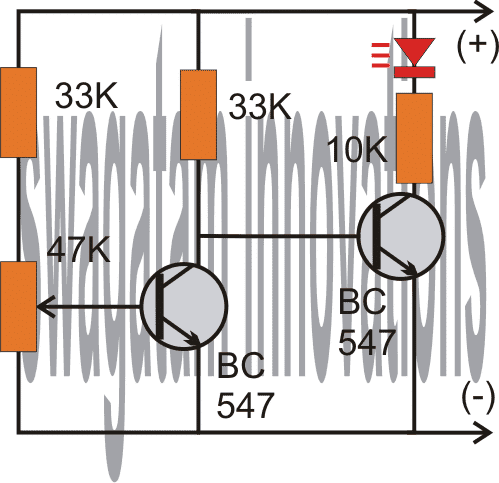
As shown in the following circuit diagram, the two transistors are configured as voltage sensor and inverter.

The first transistor on the left senses the threshold voltage level as per the setting of the 47K preset. As long as this transistor conducts, the second transistor on the right is held switched OFF, which also keeps the LED switched OFF.

As soon as the battery voltage falls below the set threshold level, the left transistor is no longer able to conduct.

This situation instantly switches ON the right hand side transistor, enabling the LED to illuminate.

The LED switches ON and provides the required indications of a low battery warning.

Circuit Diagram
low battery indicator circuit using two transistors

Audio/Video Explanation:

The above circuit was successfully built and installed by Mr. Allan in his paranormal depletion detector unit. The following video presents the implementation results:

Upgrading the above Transistorized Low Battery circuit into a Low Battery Cut-off Circuit
low battery indicator with relay cut off

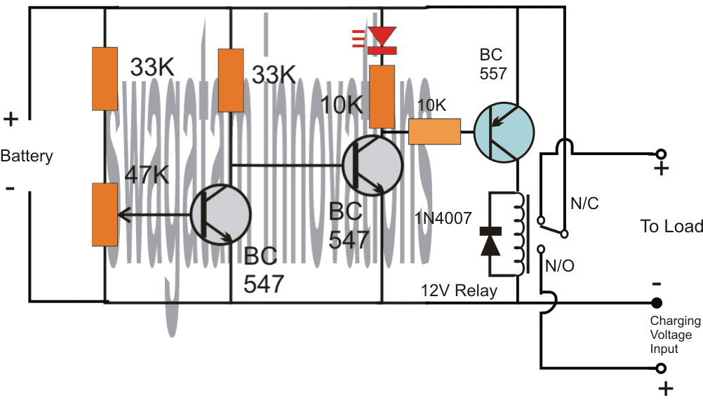
Referring to the above diagram, the low battery indicator is formed by the two NPN transistors, while the additional BC557 and the relay are used for cutting OFF the battery from the load when it reaches the lower threshold, in this state the relay connects the battery to the available charging input.

However when the battery is in its normal state the relay connects the battery with the load and allows the load to operate through battery power.

Adding Hysteresis

One drawback of the above design could be the chattering of the relay at the threshold voltage levels, due to the battery voltage dropping immediately during the relay changeover process.

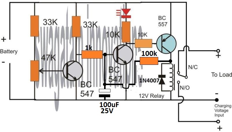
This can be prevented by adding a 100uF at the base of the middle BC547.

However, this still wouldn't stop the relay from constantly switching ON/OFF at the low battery changeover threshold.

In order to rectify this, a hysteresis effect will need to be introduced which can be accomplished through a feedback resistor between the collector of the BC557 and the middle BC547 transistor.

The modified design for implementing the above condition can be seen in the following diagram:
adding hysteresis to relay cut off

The two resistors, one at the base of BC547 and the other at the collector of BC557 decide the other threshold of the relay changeover, meaning the full charge cut off threshold of the battery.

Here, the values are arbitrarily selected, for accurate results these values will need to be optimized with some trial and error.

Low Battery Indicator using a PUT

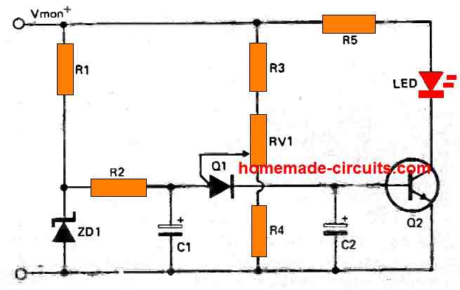
This low battery indicator circuit is used with a programmable unijunction transistor (PUT), since the threshold characteristics of the UJT could be effectively defined, and can be designed to flash a connected LED indicator.

The PUT (Q1) is configured like a relaxation oscillator circuit.

As the supply voltage which is being monitored (Vmon) starts dropping, the gate voltage of the PUT (Vg) also begins dropping, while its anode voltage (Va) basically stays constant.
low battery indicator using a programmable unijunction transistor

The PUT begins oscillating only as soon as the gate voltage drops below Va by 0.6 volts. As Vmon comes down further, Vg also drops accordingly and this situation triggers ON the PUT.

Therefore, the period of the cycle becomes lesser and this causes an increase in the frequency of flashing indicating that the battery has become too low and needs to be changed.

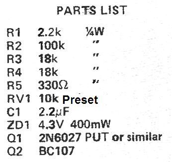
Parts List
parts list

Car Low Battery Monitor Circuit using a Single BJT

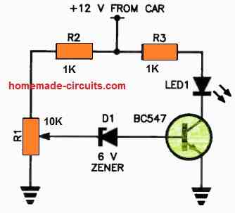
Here's a straightforward car battery monitor that eliminates the need for constant meter watching.

When your battery terminal voltage reaches a reasonable level, such as 12.5 volts as measured by a digital multimeter (DMM) or a reliable meter, you can adjust resistor R1 until the LED illuminates.
single transistor car battery low indicator circuit

If the battery voltage drops below this threshold, the zener diode will switch to a non-conductive state, cutting off the base current to the transistor.

As a result, there will be no collector current, causing the LED to turn off.

If you don't notice the small indicator light shining on your dashboard, it could indicate a low battery condition!

It's advisable to use a green LED for better visibility. For R1, it's recommended to use a 10-turn trimpot for precise adjustments.

You'll also like:

  • P 20161105 061716Arduino Battery Level Indicator Circuit
  • Battery Backup Time Indicator Circuit
  • Parallel Battery Charger Circuits Explained
  • water2BheaterSolar Water Heater Circuit with Battery Charger

Filed Under: Battery Charger Circuits Tagged With: Battery, Indicator, Only, Transistors

About Swagatam

I am an electronics engineer and doing practical hands-on work from more than 15 years now. Building real circuits, testing them and also making PCB layouts by myself. I really love doing all these things like inventing something new, designing electronics and also helping other people like hobby guys who want to make their own cool circuits at home.

And that is the main reason why I started this website homemade-circuits.com, to share different types of circuit ideas..

If you are having any kind of doubt or question related to circuits then just write down your question in the comment box below, I am like always checking, so I guarantee I will reply you for sure!


Previous Post: « Long Range Transmitter Circuit – 2 to 5 Km Range
Next Post: High Current 209A, 75V MOSFET IRFP2907 Datasheet »

Reader Interactions

Questions & Answers

Total Posts: 211
Newest Oldest
Norman D Kelley
August 7, 2026 • 5 days ago #211477

Hi Swagatam,
You are correct. I needed three resistors. One for the wiper and one for each of the side legs to voltage and ground. It works as expected. Thanks!

Reply
SwagatamAdmin
August 7, 2026 • 5 days ago #211481

Thanks Norman, glad it is solved now…

Reply
Norman D Kelley
August 1, 2026 • 2 weeks ago #211113

Hi Swagatam. Referencing the top circuit of the 2-transistor low battery indicator, how can I replace the 47k variable resistor with a fixed resistor? I have tested the circuit with a 50k preset and determined that the resistance between the pin connected to voltage through the 33k resistor to the wiper to be 33.73k ohms. The connection between the ground connected pin and the wiper to be 15.48k ohms. I would like to replace the variable resistor with a fixed resistor in series with the 33k ohm resistor. I have tried it and it doesn’t work the same as the variable resistor. I am working with a 3.7v Lipo battery and would like the indicator to light when the battery voltage gets to 3v. Help! Thanks!

Reply
SwagatamAdmin
August 1, 2026 • 2 weeks ago #211118

Hi Norman,
I hope you included 3 values for the resistances, 33k plus the two side-arm values of the preset.
In that case, it should have worked if the fixed resistor values are precisely the same.
The other easy option could be to replace the above resistances with a zener diode on the positive side and a 4.7k resistor on the ground side, and the base being connected at the junction of these two components through a 1k series resistor.
The zener value can be selected as a 3V zener.

Reply
nvthieu
February 20, 2025 • 1 year ago #168536

Can you give me the circuit to indicate the 6v voltage drop of the 8.4v source?

Reply
SwagatamAdmin
February 20, 2025 • 1 year ago #168537

You can use the first circuit from the above article.
Feed 6V as the supply DC, and tweak the preset so that the LED just lights up at this supply voltage.

Reply
Aaron M
December 12, 2024 • 2 years ago #167116

For the low battery indicator (2 transistor type), would I need different components for a 24V battery setup? Also: Could I substitute a lamp holder with a #387 lamp (28V, 1.12W, 0.04A) for the LED without trouble, or would changes be needed?

Reply
SwagatamAdmin
December 12, 2024 • 2 years ago #167123

You can use the same circuit without any changes for a 24V supply, but for a #387 lamp you will have to replace the right hand side BC547 with a 2N2222 transistor. The LED + 10k resistor can then be removed and replaced with the lamp.

Reply
Aaron M.
December 18, 2024 • 2 years ago #167420

I suppose I could use a 50k trimmer for the variable resistor instead of 47k?

Reply
SwagatamAdmin
December 18, 2024 • 2 years ago #167424

Sure, you can use it…

Reply
Yakub Ismail
December 4, 2024 • 2 years ago #166577

I want to latch the other circuit when the battery voltage is low but I need a positive voltage for that can I change right side transistor connecting it’s collector to positive supply so that I can get positive from emmeter will it work

Reply
SwagatamAdmin
December 5, 2024 • 2 years ago #166620

Which other circuit are you referring to?

Reply
josh
December 26, 2022 • 4 years ago #137960

Hello again and thanks another reply. Now I understand. I didn’t realize that the potentiometer it’s self functions as a voltage divider. My only experience with them before now was when wiring my guitars and I always thought of them as them as purely resistive components. Anyways, appreciate the responsiveness

Reply
SwagatamAdmin
December 26, 2022 • 4 years ago #137968

No problem! I am glad I could help. All the best to you.

Reply
Josh L Standridge
December 22, 2022 • 4 years ago #137858

Thanks again for the reply. I understand the concept of the circuit, just not how with the given values it would work. If the 33k and 47k potentiometer/resistor serve as a voltage divider, then wouldn’t the voltage have to drop to around 1.5 volts before the first transistor would stop conducting?

Reply
SwagatamAdmin
December 23, 2022 • 4 years ago #137877

The potentiometer can be used to adjust the cut off threshold to any desired value with respect to the battery voltage. So if you want the left BC547 to cut off at 11 V, you can adjust the potentiometer accordingly, similarly you can do the same for any other battrety voltage such as 10 V, 10.5 V or 9V etc. The potentiometer gives you the full freedom to adjust the cut threshold to any desired values, as required.

Reply
josh
December 21, 2022 • 4 years ago #137818

Hello, not understanding the circuit function of the first 3 diagrams. Wouldn’t more voltage drop across the 33-k resistor biasing the led transistor since there’s the additional 48 k at the base of the first? Also why is there any arrow pointing outward from the base of the first transistor being an npn? Thanks

Reply
SwagatamAdmin
December 22, 2022 • 4 years ago #137832

Hello, the 47K resistors is a potentiometer, or it can be a preset, or a trimpot. The arrow indicates the wiper arm of the potentiometer which is connected with the base of the transistor.

Reply
josh
December 22, 2022 • 4 years ago #137837

Thank you for the response. I’m still not understanding how the first transistor stops conducting at the threshold voltage with it being above 0.7 volts or how the other transistor doesn’t conduct first being that there’s less resistance to its base? I’m new to electronics so I’m probably missing something obvious here.

Reply
SwagatamAdmin
December 22, 2022 • 4 years ago #137839

Let’s assume the 47K trimpot is adjusted such that the base voltage of the left BC547 drops below 0.7 V when the battery voltage drops below 11 V. This means, as long as the battery voltage is above 11 V, the left BC547 remains switched ON, which causes the base voltage of the right side BC547 to be grounded. Due to this the right side BC547 remains turned OFF, and the LED also remains shut off.
Now, in a situation when the battery voltage drops below 11 V, the base voltage of the left BC547 also correspondingly drops below 0.7 V, which causes it to shut off. When this happens, the right side BC547 base starts getting the biasing voltage through its 33 K resistor and it switches ON. This also allows the LED to switch ON and indicate the low battery condition.

Reply
ACG
September 14, 2022 • 4 years ago #133238

Nice, but a bit dated.
PMIC supervisor IC chips have long since advanced the art of low voltage detection. The operating currents are in the 10uA to 1uA (micro) range. The pin counts are down to 3 pins. Hysteresis is built in. Price is under 50 seconds for singles and dirt cheap for larger quantities.

Reply
CHINOMSO
October 28, 2021 • 5 years ago #102917

Hello sir, please I need your urgent help with this; Is there a way you could modify your above circuit further to include another stage of switching so as to sound a buzzer alarm at 11 volts (for a case of 12v power supply) to warn of low battery before switching of the relay at about 10.5v. I have really tried this with a trial and error method several times, wasting a lot of transistors in the process. Please sir, I would be glad you illustrate with with a diagram. Thanks in anticipation.

Reply
SwagatamAdmin
October 28, 2021 • 5 years ago #102933

Hello Chinomso, there’s no question of wasting transistors in the above circuits, because the transistors are safe and can never burn.

If you want a sharp response then instead of transistors you can use an opamp based design, as shown below:

SG3525 battery low voltage latching compressed

This had been designed for SG3525 inverter, therefore ignore the pin#10 indication.

Also you can remove the 4k7 and 1k from the output of the opamp and connect the buzzer directly from battery positive to pin#6 of the op amp.

You can remove the hysteresis network which uses 1N4148 diode and series 1K.

You can make another similar circuit for activating a relay through a driver transistor. If you are using a transistor with the op amp then the 4k7 and 1k at the output should be included in the circuit, and the transistor base connected to the 4k7 / 1K junction.

Reply
CHINOMSO
October 30, 2021 • 5 years ago #103218

Hello sir, can LM393 opamp be used in the two stage mode, such that : the pin 1 of the ic, for instance, controls the relay, while the pin 7 controls the buzzer for low battery warning?. If it can, please i would be very happy if you could provide me with good diagram to that design. I would love to use 741 opamp as you adviced, but considering space, power consumption and circuit ambiguity, I would want it on a single source. Thanks

Reply
SwagatamAdmin
October 30, 2021 • 5 years ago #103227

Hello Chinomso, the IC 741 can be used with a single power supply, the -battery indicates the 0V or the ground of the Dc supply.

You can try the following configurations using the LM393 IC:

low battery cut off with battrey using IC LM393

Reply
CHINOMSO
November 1, 2021 • 5 years ago #103405

Thanks alot sir, I’ll try this

Reply
SwagatamAdmin
November 1, 2021 • 5 years ago #103413

You are welcome Chinomso, there’s a small mistake in the diagram, the feedback diode 1N4148 must be connected to pun#3 of the opamp and its polarity must be reversed.

Reply
CHINOMSO
October 29, 2021 • 5 years ago #103005

Thank you so much for the circuit, I really appreciate. However sir, i chose the transistor based because I really want to save as much power as I could. Hence, the circuitry should be such that it would be required to have a two stage switching, such that a set of transistors in TTL mode switches the buzzer on at 11 volts, then as the battery voltage reduces further to 10.5 volts, another set of transistor switches off the relay. I need this in my inverter circuit and would so much appreciate it I could get this from you. Thanks alot

Reply
SwagatamAdmin
October 29, 2021 • 5 years ago #103052

Hello Chinomso, transistor circuit will not be able to provide precise cut offs, sometimes it may be at 10.5V and sometimes 10V or sometimes 10.8V

Reply
CHINOMSO
October 30, 2021 • 5 years ago #103214

I really would be completely blind to these things If not for your help. I really appreciate you sir

Reply
SwagatamAdmin
October 30, 2021 • 5 years ago #103223

I am glad to help Chinomso!

Reply
Joe
October 10, 2021 • 5 years ago #100648

Can BC337 be used instead of BC547 in first circuit?

Reply
SwagatamAdmin
October 10, 2021 • 5 years ago #100654

Yes, can be used.

Reply
Gogulanath Sivaprakasam
August 2, 2021 • 5 years ago #92960

Hi sir
Can this be optimized for 24 v system

Reply
SwagatamAdmin
August 2, 2021 • 5 years ago #92963

Hi Gogulanath, you can use the same circuit without any customization for 24V also….for the relay circuit, you may have to replace the 12V relay with a 24V relay.

Reply
Patrick
May 20, 2021 • 5 years ago #90122

Thanks for this site and for posting this circuit. I have been getting back into electronics with my kids after many years off and your site is great for that purpose. I have a couple of questions about the first circuit (the one that only lights the LED).

1. In the 12.5V +/- 1V range using a 10k LED for the load this circuit will power the LED with 1.2mA. What LED works at 1.2mA? I usually see current ranges in the 20-30mA. I think I need to lower both the LED driving transistors base and collectors resistors substantially. According to LTSpice 10k and 390 are working values for those two resistors.

2. How stable do you think the triggering threshold be over time? Let’s say that it triggers at 12.5V at room temp using a BC547B (which may or may not have higher gain than BC547). How likely is it to trigger at the same over a long period of time and a range of different temperatures?

Thanks

Reply
SwagatamAdmin
May 20, 2021 • 5 years ago #90123

Thank you for asking this question:
1) I normally use 10K for my red LEDs since they look too bright for any other lower resistor values. The resistor values can be tweaked, there are no criticality regarding the values of the resistors, because ultimately it’s the preset adjustment that decides the detection thresholds.

2) The transistors will start giving wrong results after around 37 or 40 degrees Celsius, under this the results can be expected to be fairly consistent. The preset quality will also affect the results over a long period of time, since the preset contacts may get dirty and loose or might deviate from the initial adjustment.

Reply
Yogesh
May 5, 2021 • 5 years ago #89005

Thanks a lot sir, This circuit is very helpful to me and it is easy to understand ????

Reply
SwagatamAdmin
May 5, 2021 • 5 years ago #89007

You are welcome Yogesh, I appreciate your kind feedback!

Reply
Al
March 18, 2021 • 5 years ago #87800

Hello

I have a battery holder that doesnt have a battery low indicator but I have access to the board.
This solution is exactly what I am looking for. Can you help not an EE

Reply
SwagatamAdmin
March 18, 2021 • 5 years ago #87805

What help do you need?

Reply
Dane
June 25, 2020 • 6 years ago #79823

As you know, I don’t know much but it looks like it might be easier to keep with your initial design for low battery but have it wired to an additional green LED that is manufactured to blink or flash. I think they make them like that. Am I right to stick with your old way and have the additional blinking green LED?

Reply
SwagatamAdmin
June 25, 2020 • 6 years ago #79832

No Problem Dane!

Reply
Dane
June 24, 2020 • 6 years ago #79806

I forgot to mention I will be using a 9 volt battery

Reply
Dane
June 24, 2020 • 6 years ago #79805

I found a guy who is trying to design a PCB for me. I am very excited and will keep you posted.
Thank you so much for your help. I was wondering if you could help me again.
I am wondering if there is a way to adapt and change your low battery circuit to do what I need.
I have a switch that operates from 1 volt to 24 volts. It has 3 connectors. One is a Common. The other is a Normally Open connector that goes to my Green LED when the switch is on. It has a Normally Closed connector that goes to my Red LED when the switch is off. I would like to avoid adding another LED for the low battery indicator (was going to use a yellow led). Instead, is there a way to make my Green LED blink on and off when the battery gets low? Using only 2 LED’s would really help. Thank you again for your input.

Reply
SwagatamAdmin
June 24, 2020 • 6 years ago #79814

That great news! However, getting the LED to flash can make the design a bit complex. You can try the last circuit explained in the following article, hope this might help you accomplish your requirement:

https://www.homemade-circuits.com/flashing-led-battery-status-indicator/

Reply
Dane
June 15, 2020 • 6 years ago #79533

I will look into finding a company that can do that here. Thank you again!

Reply
SwagatamAdmin
June 15, 2020 • 6 years ago #79536

Sure, I hope you find an appropriate source soon.

Reply
Dane
June 15, 2020 • 6 years ago #79510

Great! Thanks for the clarification. I will start with the 2K2 and see if it’s bright enough. I have a hand drawn diagram of what I am trying to accomplish but it is terrible and I am too embarrassed to post it publicly. I think I am going to need someone to draw it out for me so that maybe I can have a small PCB made. Any ideas on who might be good to help with that?
Thanks again!

Reply
SwagatamAdmin
June 15, 2020 • 6 years ago #79522

Thanks very much, I understand your problem, however I do not have anybody who can design PCBs correctly, since it is a specialized job and must be done in accordance with the standard PCB designing rules. I guess Only a PCB manufacturer will be able to draw it correctly.

Reply
Dane
June 14, 2020 • 6 years ago #79504

Hi again!
Could you please clarify the circuitry of your low battery warning design?
The photo you sent me shows a 1k resistor (bottom right) but the diagram shows a 2k2 resistor.
Which one should I use?

Reply
SwagatamAdmin
June 14, 2020 • 6 years ago #79505

Hi, It can be any value between 680 ohms ohms and probably 10 k for supplies between 9V and 15 V, so you can use any resistor between this range although the light will decrease as the value is increased.

Reply
Dane
June 7, 2020 • 6 years ago #79266

Will do!

Reply
Dane
June 6, 2020 • 6 years ago #79249

Thanks for the offer. I had planned on sending you a picture of my completed project for your opinion. Any idea how to attach a picture for you and how to send?

Reply
SwagatamAdmin
June 7, 2020 • 6 years ago #79263

OK, for the picture you can upload it to any “free image hosting site’, and provide the link to me, I’ll check it and verify the details for you

Reply
Dane
June 5, 2020 • 6 years ago #79230

Once again you have been very, very helpful. I have ordered all of the parts and will start testing the different resistors as soon as they all arrive. Thank you again so much and I hope you can some day make it to Florida!

Reply
SwagatamAdmin
June 6, 2020 • 6 years ago #79236

The pleasure is all mine! please feel free to comment back if you face any problems with the projects!

Reply
Dane Shearer
June 4, 2020 • 6 years ago #79217

Wow! That picture really helped a lot! That solves my low battery problem very well and thank you so much. Now I need to use the rest of the info you gave me to complete my project. Since I don’t need my green LED to be very bright but always “On” which resistor would you recommend for longest battery life for my 9 volt battery?
Thank you so much again!
(PS. If you ever come to Florida, at least let me buy you dinner!)

Reply
SwagatamAdmin
June 5, 2020 • 6 years ago #79225

Thanks very much, Glad you found it useful! The green LED illumination will need to be checked practically since different brands have different quality standards. You can start with a 470 ohm resistor and then try a few higher values, like 560 ohms or 680 ohms until you find the right one which provides just the right illumination yet uses a reasonably high resistance value. The 330 ohm is the lowest threshold, so the value must be higher than this value.

It’ll be a pleasure meeting you if I ever happen to visit Florida, thanks for the invitation.

Reply
Dane Shearer
June 3, 2020 • 6 years ago #79202

Thank you and I think that all makes sense. You have been very helpful however I know nothing about electronics and I don’t understand the electrical drawing showing the arrow coming from #2 on the IC 741 to the 10k Preset. It doesn’t look soldered to the preset. It just points at it.
Is there a way I can pay you to make one of what I am needing using the actual parts so that I can remake it here? I would LOVE to do that and pay for it.
That way I know I could follow what you are so kindly recommending.
Thank you again, Dane

Reply
SwagatamAdmin
June 4, 2020 • 6 years ago #79210

Hi, thank you, I understand and appreciate your generosity, however payment may not be required, I’ll help you anyway until your goal is accomplished, because the concept is quite simple and basic.

Please go to the previous IC 741 link, and check the first diagrams, I have updated it in a pictorial format using real part images. This will help you to understand how each part needs to be connected practically.
Let me know if you have any more doubts.

Reply
Dane Shearer
June 2, 2020 • 6 years ago #79187

Thank you so much for your response.

I need a lot of help designing a 9 volt alarm that we are going to make and resell. In this alarm, a piezo alarm will go off with a red LED light when switched to do so. ( I already have the switching device – it measures air pressure with normal NO NC and Common) The alarm will have a green LED that will be on all of the time unless air pressure is lost which is measured by the switch.

I need help selecting the right snap in 5mm LED’s (and or resistors) so the LED’s will last at least 10 years and not drain much of the 9 volt battery. A green LED will be on all of the time unless switched off at which point the alarm and red light switches on.

I need another properly designed LED (yellow) to light up when the 9 volt battery gets low and needs to be replaced. Either that or the green or red light could flash to warn of low battery. I don’t know how to make a low battery light up a yellow light or make a green or red flash.

Thank for your consideration and I would be happy to pay for your time

Dane Shearer
ddj100@aol.com

Reply
SwagatamAdmin
June 2, 2020 • 6 years ago #79189

Hi, thanks, The requirement looks very basic so I will explain it to you here quickly. Assuming you are using the standard 20 mA 3.3 V LEDs, the resistor values that will limit the LEDs with 20 mA could be calculated using the following formula:

R = V – LED fwd V / LED current, where V is the 9 V, LED fwd V is 3.3 V, and LED current is = 20 mA or 0.02 Amp
Therefore R = 9 – 3.3 / .02 = 285 Ohms. However, choosing a higher value than this is recommended which will ensure lower current than the optimal 20 mA value and will enable the device to have a much longer life. So instead of 285 Ohms we can go for 300 Ohms or a 330 Ohms 1/4 watt 5% watt

Flashing the red or green LED may require a more elaborate electronics and part count, so illuminating a separate yellow LED will be a better option.

Since the response must be sharp and accurate I would suggest an op amp based low batt detector as shown in the first diagram from this article:
https://www.homemade-circuits.com/how-to-make-simple-low-battery-voltage/

The red LED should be replaced with a yellow. The LED resistor may be calculated as described in the previous paragraphs.

Reply
SwagatamAdmin
June 2, 2020 • 6 years ago #79190

You can even go for higher resistance values than 330 ohms, may be up to 680 ohms, because today the modern LEDs are designed to produce high bright illumination even with minimal current supplies. Lower current or higher series resistor will mean longer life for the LEDs and the battery…

Reply
Dane Shearer
June 1, 2020 • 6 years ago #79170

Hi there,
I am designing an alarm to be manufactured and resold by my wife and I. I know marketing not electronics. We need help designing a hopefully simple Green LED – “On”, Red – “Off” and Yellow (Or flashing Red) “Replace 9 volt battery” Are you available for such a project?
Thank you, Dane

Reply
SwagatamAdmin
June 1, 2020 • 6 years ago #79172

Hi, I can try. Please provide the working specifications in detail, I’ll try to figure it out for you.

Reply
Ahmed Alissa
May 17, 2020 • 6 years ago #78763

Thank you for your efforts 🙂

I’ve used the 1st circuit in a small project and it worked perfectly.
Is it possible to make the led blink instead of always ON without affecting the 1.5mA draw current?, (my goal is to make it more noticeable and save power)

Reply
SwagatamAdmin
May 18, 2020 • 6 years ago #78789

You can perhaps try integrating the following circuit across the collector of the low battery circuit
https://www.homemade-circuits.com/how-to-make-single-transistor-led/

Reply
Ahmed Alissa
May 20, 2020 • 6 years ago #78835

I looked into that before, and some other online circuits, my problem is that I need this flashing indicator for single 18650 (3.7v), the posted indicator circuit is working with low voltage but the flashing circuits I found doesn’t.

Reply
SwagatamAdmin
May 20, 2020 • 6 years ago #78837

You can buy a readymade flashing LED that does not require any circuit.

Reply
harold ilano
January 13, 2020 • 7 years ago #74516

it’s a simple and a perfect one (for my project)! minimal components but very effective. thank you for this, sir!

Reply
harold ilano
January 13, 2020 • 7 years ago #74519

you’re welcome, sir. take care!

Reply
SwagatamAdmin
January 13, 2020 • 7 years ago #74518

Glad you liked it, thanks for your feedback…

Reply
Vaisakhan
August 1, 2019 • 7 years ago #68925

Also, I am charging the battery from a solar panel via charge controller. So during night time no means to charge the battery.

Reply
LEO SMIT
October 15, 2019 • 7 years ago #71106

Dear sir,

when the led is on, let’s say at 5V as in the video, BC 557 conducts, and the relay-voltage drops to 5V .
the relay is supposed to go on, but the relay that is used is 12 V, so it is not sure that it’s gonna work at 5V…

Reply
SwagatamAdmin
August 1, 2019 • 7 years ago #68927

You can modify one of the circuits from this article:

https://www.homemade-circuits.com/simple-dc-ups-circuit-for-modemrouter/

Replace the battery with solar panel. And put the battery in place of the Modem/Router

Reply
Chris Morey
February 17, 2020 • 6 years ago #76729

I have numerous 2S rc lipo’s 8.4v charged. We store them at 7.4 volts. I was wondering if this circuit would allow us to discharge the battery with a 5 amp load, and then have this circuit disconnect the battery at 7.4 volts. Y

Reply
SwagatamAdmin
February 18, 2020 • 6 years ago #76739

yes you can try the last circuit for the mentioned purpose!

Reply
Vaisakhan
August 1, 2019 • 7 years ago #68924

Good Day Swagat,

I made the 2nd circuit and I am using it in a 12 v battery to light up an a 12 v led & I have an issue, that just before cut off voltage the relay start chattering. I selected cut off voltage 10.7V. How can I avoid this issue?

Reply
Leo Smit
February 11, 2020 • 7 years ago #76414

Dear sir,
I have the same problem with the relay and placed the resistor 100Kohm and 100uf/25v , but at the threshold-voltage the relay starts chattering (only when the charging voltage is also present).
Due tot the fact that the charging voltage( 13,7 volt) takes over the working circuit , the circuit thinks that it can work as usual with full battery , it will try to switch the relay to normal (load) and then recognizes that battery is to low and then switches again to charger (and vice cersa)
Don’t know how to prevent that, but maybe you have a suggestion?

Reply
SwagatamAdmin
February 12, 2020 • 7 years ago #76428

Hi Leo, you are right, and this can be prevented by adding a hysteresis effect in the circuit. The hysteresis or latching effect will work if a resistor is introduced at the base of the middle transistor…I forgot to mention this earlier. So please put a 1k resistor in series with the base of the middle BC547, and now connect a 100k resistor between the collector of BC557 and the base of the middle BC547.

Reply
leo smit
February 12, 2020 • 7 years ago #76441

will for sure try this, the 100kohm from bc557 to bc547 was allready placed, so the 1k must do the trick
thank you!

Reply
SwagatamAdmin
February 12, 2020 • 7 years ago #76444

No problem….also I have updated the new design at the bottom of the article.

Reply
SwagatamAdmin
August 1, 2019 • 7 years ago #68926

Good day Vaisakhan, you can try adding a 100uF/25V across the base/emitter of the BC557. negative terminal will go to the base.

Reply
Vaisakhan
August 1, 2019 • 7 years ago #68940

Thanks for your quick response. Added the additional capacitor but not solved the issue. Once the load disconnected from battery due to low voltage, slowly battery voltage tends to rise & it is again connected the load. This cycle keep on repeating. Any way to solve this issue?

Reply
SwagatamAdmin
August 1, 2019 • 7 years ago #68941

The remedy which I suggested was to prevent chattering of relay at the threshold, it won’t prevent the cyclic action when the battery voltage rises. If you wish to latch it, you can add a 100K resistor between the collector of BC557, and the middle BC547 base.

Reply
Sam
April 23, 2019 • 7 years ago #66632

Please will this circuit work with a 4s lipo battery which is 14.8v. And 16.8v charged voltage?

Reply
SwagatamAdmin
April 23, 2019 • 7 years ago #66634

Yes, it can work for all types of batteries

Reply
Lisa Lisa
October 11, 2019 • 7 years ago #70940

Yes… I conform it does work at Lipo voltages… I wish their was something you can add for a little hysteresis…

Reply
Dhits Gomnic
December 20, 2018 • 8 years ago #64648

Good Day Sir! Looks like the circuit of 741 here is missing sir. 🙂 The one that automatically switch the load to source and battery 🙂

Reply
SwagatamAdmin
December 21, 2018 • 8 years ago #64654

Hi Dhits, it was redirecting to a wrong post due to a site misconfiguration, here’s the actual you are looking for 😉 please check this out

https://www.homemade-circuits.com/2012/01/how-to-make-simple-low-battery-voltage.html

Reply
scott cacciamani
February 26, 2018 • 8 years ago #58767

sorry i’m having so much trouble with this. the center lug of 547 near the 47 k resister is soldered exactly where? The center lug of the 47k trim pot goes under which base, the base of itself or the 547. also where can i find a diagram on how to hook up a on off switch to this? You can tell i have no experience.

thanks again

Reply
SwagatamAdmin
February 26, 2018 • 8 years ago #58776

What is so complicated? Please make your assembly layout exactly as shown in the diagram, place the components on the PCB exactly as presented in the diagram, then you have any problems.

The 47k preset will have 3 leads, the center one connects with the base…out of the other two, one goes to the ground, the other to the 33K.

If you are making it over a breadboard then it can a lot confusing for you.

And make sure to check the base, emitter, collector pins of the BC547 correctly

Reply
scott cacciamani
February 23, 2018 • 8 years ago #58715

sorry, forgot the last one. Is the 47k resester center lug soderd directly to the center lug of the bc-547?

Reply
SwagatamAdmin
February 24, 2018 • 8 years ago #58724

it is directly connected to the base, because we already have a series resistor with the positive arm of the preset.

Reply
scott cacciamani
February 23, 2018 • 8 years ago #58714

Hi, again, when using a power supply to set the low voltage on the 47k trim pot. i assume i hook up the leads positive to positive and neg to neg, but what voltage should i set the power supply at before turning the screw on the trim pot. This would be for a low voltage indicator of a 9v battery

Reply
SwagatamAdmin
February 24, 2018 • 8 years ago #58723

apply 8.25V to the circuit, and adjust the preset such that the LED just begins illuminating, that’s all.

Reply
View Older Comments

Need Help? Please Leave a Comment! We value your input—Kindly keep it relevant to the above topic! Cancel reply

Your email address will not be published. Required fields are marked *

Primary Sidebar


Categories

  • Arduino Projects (95)
  • Audio and Amplifier Projects (134)
  • Automation Projects (18)
  • Automobile Electronics (104)
  • Battery Charger Circuits (90)
  • Datasheets and Components (109)
  • Electronics Theory (150)
  • Energy from Magnets and Earth (41)
  • Games and Sports Projects (11)
  • Grid and 3-Phase (20)
  • Health related Projects (27)
  • Home Electrical Circuits (13)
  • Indicator Circuits (16)
  • Inverter Circuits (100)
  • Lamps and Lights (163)
  • Meters and Testers (72)
  • Mini Projects (28)
  • Motor Controller (68)
  • Oscillator Circuits (30)
  • Pets and Pests (15)
  • Power Supply Circuits (91)
  • Remote Control Circuits (50)
  • Security and Alarm (65)
  • Sensors and Detectors (107)
  • SMPS and Converters (46)
  • Solar Controller Circuits (62)
  • Temperature Controllers (44)
  • Timer and Delay Relay (50)
  • Voltage Control and Protection (44)
  • Water Controller (37)
  • Wireless Circuits (31)


Circuit Simulator

circuit simulator image


Subscribe to get New Circuits in your Email


Other Links

  • Privacy Policy
  • Cookie Policy
  • Disclaimer
  • Copyright
  • Videos
  • Sitemap

People also Search

555 Circuits | 741 Circuits | LM324 Circuits | LM338 Circuits | 4017 Circuits | Ultrasonic Projects | SMPS Projects | Christmas Projects | MOSFETs | Radio Circuits | Laser Circuits | PIR Projects |


Recent Comments

  • Swagatam on Simple Walkie Talkie Circuit
  • Swagatam on Electronic Circuit Projects, Tutorials, and Practical Engineering Solutions
  • Swagatam on How to Replace a Transistor (BJT) with a MOSFET
  • SA on How to Replace a Transistor (BJT) with a MOSFET
  • Adil on Simple Walkie Talkie Circuit

Social Profiles

  • Twitter
  • YouTube
  • Instagram
  • Pinterest
  • My Facebook-Page
  • Stack Exchange
  • Linkedin

© 2026 · Swagatam Innovations