In this post I have explained 2 simple universal current controller circuits which can be used for safely operating any desired high watt LED.
The universal high watt LED current limiter circuit explained here can be integrated with any crude DC supply source for getting an outstanding over current protection for the connected high watt LEDs.
Why Current Limiting is Crucial for LEDs
We know that LEDs are highly efficient devices which are able to produce dazzling illuminations at relatively lower consumption, however these devices are highly vulnerable especially to heat and current which are complementary parameters and affect an LED performance.
Especially with high watt LEds which tend to generate considerable heat, the above parameters become crucial issues.
If an LED is driven with higher current it will tend to get hot beyond tolerance and get destroyed, while conversely if the heat dissipation is not controlled the LED will start drawing more current until it gets destroyed.
In this blog we have studied a few versatile work horse ICs such as LM317, LM338, LM196 etc which are attributed with many outstanding power regulating capabilities.
LM317 is designed for handling currents up to 1.5 amps, LM338 will allow a maximum of 5 amps while LM196 is assigned for generating as high as 10 amps.
Here we utilize these devices for current limiting application for LEds in the most simplest possible ways:
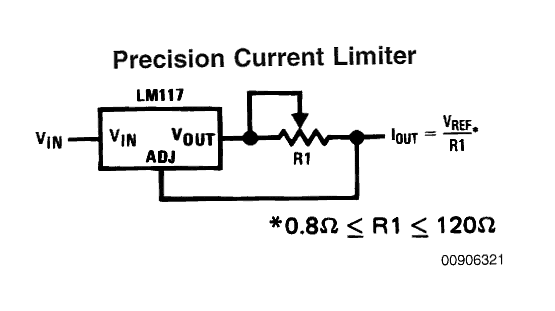
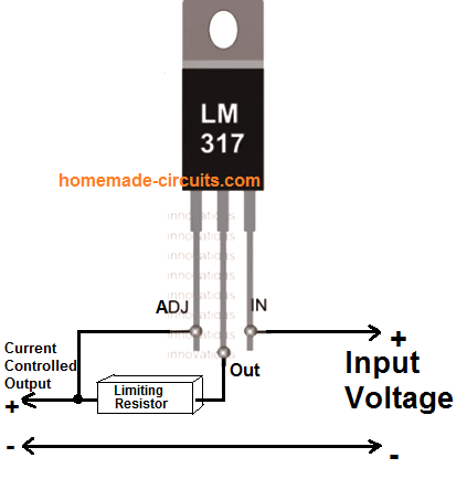
The first circuit given below is simplicity in itself, using just one calculated resistor the IC can be configured as an accurate current controller or limiter.
Calculating the Current Limiter Resistor
The figure shows a variable resistor for setting the current control, however R1 can be replaced with a fixed resistor by calculating it using the following formula:
R1 (Limiting Resistor) = Vref/current
or R1 = 1.25/current.
R1 wattage = R x I2
Current may be different for different LEDs and can be calculated by dividing the optimal forward voltage with its wattage, for example for a 1watt LED, the current would be 1/3.3 = 0.3amps or 300 ma, current for other LEDs may be calculated in similar fashion.
The above figure would support a maximum of 1.5 amps, for larger current ranges, the IC may be simply replaced with an LM338 or LM196 as per the LED specs.
Application Circuits
Making a current controlled LED tubelight.
The above circuit can be very efficiently used for making precision current controlled LED tube light circuits.
A classic example is illustrated below, which can be easily modified as per the requirements and LED specs.
30 watt Constant Current LED Driver Circuit
Assume the LEDs to be 3.3 V, 10 watt, and Supply input to be 12 V
Current of LED becomes = 10 / 3.3 = 3 amps
The LM338 current limiter can be calculated using the formula
R1 = 1.25 / 3 = 0.41 Ohms
Wattage = R x I2 = 0.41 x 3 x 3 = 3.69 watts or 4 watts
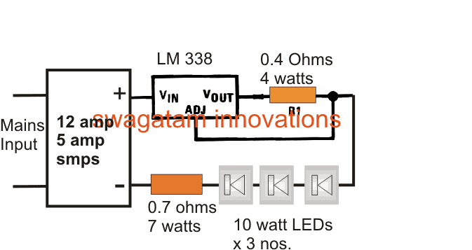
The series resistor connected with the three LEDs is calculated by using the following formula:
R = (supply voltage – Total LED forward voltage) / LED current
R(watts) = (supply voltage – Total LED forward voltage) x LED current
R = [12 - (3.3+3.3+3.3)]/3amps
R= (12 - 9.9)/3
R = 0.7 ohms
R watts = V x A = (12 - 9.9) x 3 = 2.1 x 3 = 6.3 watts
Restricting LED Current using Transistors
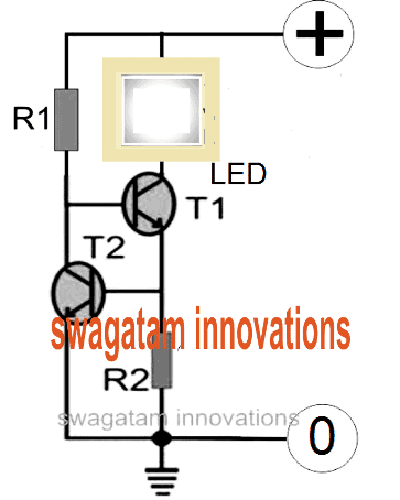
In case you do not have an access to the IC LM338 or if the device unavailable in your area, then you could simply configure a few transistors or BJTs and form an effective current limiter circuit for your LED.
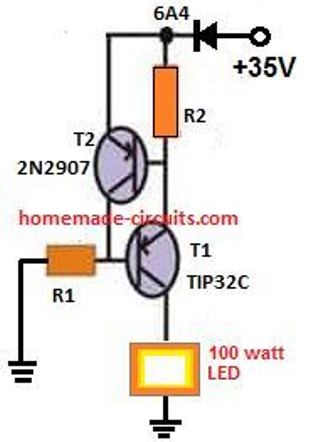
The schematic for the current control circuit using transistors can be seen below. The design is an example for a 100 watt LED current limiter, with 35V as the input supply and the 2.5 amp as the maximum current limit.
PNP Version of the Above Circuit
How to Calculate the resistors
In order to determine R1 you may use the following formula:
R1 = (Us - 0.7)Hfe/Load Current,
where Us = supply voltage, Hfe = T1 forward current gain, Load current = LED current = 100W/35V = 2.5 amps
R1 = (35 - 0.7)30/2.5= 410 Ohms,
Wattage for the above resistor would be P = V2 / R = 35 x 35 / 410 = 2.98 or 3 watts
R2 may be calculated as shown below:
R2 = 0.7/LED current
R2 = 0.7/2.5 = 0.3 ohms,
wattage may be calculated as = 0.7 x 2.5 = 2 watts
Using MOSFET for Higher Current Applications
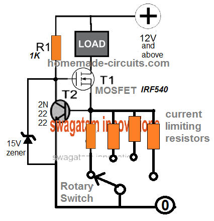
MOSFETs are more efficient than BJTs in terms of handling higher current and wattage. therefore, for applications that require high current limiting, for high wattage loads, a MOSFET can be used in place of T1.
The current handling capacity of the MOSFET will depend on its VDS and IDS ratings, with respect to the case temperature. Meaning, the MOSFET will be able to tolerate the amount of current defined by the product of its VDS x IDS, provided the case temperature does not exceed 40 degrees Celsius.
This may appear practically impossible, therefore the actual limit will be defined by the amount of VDS and IDS that allows the device to work below the 40 degrees Celsius mark.
The above BJT based current limit circuits can be upgraded by replacing T1 with a MOSFET as shown below:
The resistor value calculations will remain the same as discussed above for the BJT version

Variable Current Limiter Circuit
We can easily convert the above fixed current limiter into a versatile variable current limiter circuit.
Using a Darlington Transistor
This current controller circuit features a Darlington pair T2/T3 coupled with T1 to implement a negative feedback loop.
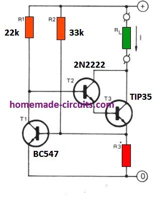
The working can be understood as follows. Let's say the input supply the source current I starts rising due to high consumption by the load for some reason.
This will result in an increase in the potential across R3, causing the T1 base/emitter potential to rise and a conduction across its collector emitter.
This would in turn cause the base bias of the Darlington pair to start getting more grounded. Due to this the current increase would get countered and restricted through the load.
The inclusion of R2 pull up resistor makes sure that T1 always conducts with a constant current value (I) as set by the following formula. Thus the supply voltage fluctuations have no effect on the current limiting action of the circuit
R3 = 0.6 / I
Here, I is the current limit in amps as required by the application.
Another Simple Current Limiter Circuit
This concept uses a simple BJT common collector circuit. which gets its base bias from a 5 k variable resistor.
This pot helps the user to adjust or set the maximum cut off current for the output load.
With the values shown, the output cut off current or current limit can be set from 5 mA to 500 mA.
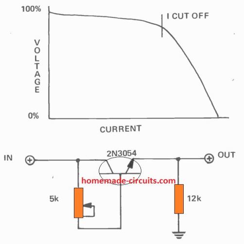
Although, from the graph we can realize that the current cut-off process is not very sharp, yet its is actually quite enough to ensure proper safety for the output load from an over current situation.
That said, the limiting range and accuracy can be affected depending on the temperature of the transistor.
Adjustable Current Controller Circuit using IC 741
The following IC 741-based arrangement can be used if you want a preset current limit which is adjustable across a wide range.
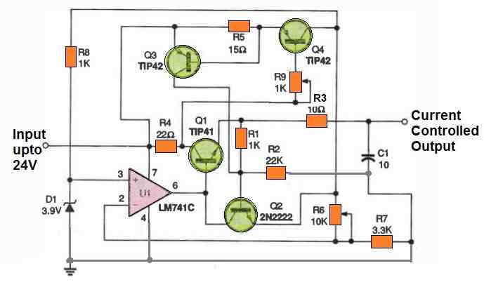
When R9 is adjusted to zero ohms, the lowest current limit for the components depicted is around 47 mA. Add a suitable fixed-amount resistor in series with R9 if you want to set a specific high current limit.
As you can clearly see, implementing current crowbars offers the excellent method of safeguarding electronics from short circuit destruction.


Questions & Answers
Hello Dr.Swagatam.
I need a variable current circuit from 0 to 10 amps with a fixed voltage of 100 volts DC, such that voltage drop does not occur. With which circuit can I achieve the desired result? Please help and introduce a complete circuit. I also have a question: what type of circuit has very high efficiency for controlling and limiting current?
a dc-dc cc cv buck converter module, but you will need many working together [or a very expensive 1] to add up to that much electricity
If you want to get it from AC, it needs a SMPS too.
Hi Muller,
You can achieve the current limit using the following module, but your voltage might drop if the oad is not compatible wiith the voltage specifications…
https://www.homemade-circuits.com/50a-high-current-sensor-ic-acs758-circuit-diagram/
Hello Dr.Swagatam.
Thank you for your quick response.
I need up to 10 amps.
Is it possible to use the SY-10T instead of the ACS758?
And in an analog circuit without Arduino, do other components need to be changed?
Hi Muller,
Although I could not find sufficient information about its circuit connections, it seems like it should work with the 741 opamp circuit for implementing the adjustable 10amp current control…
full name is “SY-10 NANA Sensors” .
that sells of it link:
veswin.com/product-SY-10.html
please check: Is it possible to use the SY-10T instead of the ACS758?
And in an analog circuit without Arduino, do other components need to be changed?
thank you very much.
Where is the datasheet? Without datasheet and pinout diagram it is impossible to know about its working details.
Yes, the opamp circuit can be used without any changes…
Hello Mr. Swagatam
I need to build a simple current limiter for a controlled electrolytic process. As my electrolysis proceeds water resistance between electrodes will drop from approx. 150kΩ to 15kΩ. With a supply voltage of 24VDC the load current would thus increase from approx. 0.16mA to 1.6mA.
My intention is to automatically limit the load current to a maximum of 0.25mA irrespective of decreasing water resistance.
Questions:
1. In your circuit “Precision Current Limiter”, if I set R1 = 100kΩ will then the output load current (Iout) be limited to 0.24mA? Would that work in my case?
2. Can LM117/317 regulators even control such low currents accurately?
3. If all this fails, could you please recommend a simple circuitry that would do the job? Thank you much!
Hi Holgar,
0.25mA indeed looks very low and might not allow the lm317 to work properly, in that case why not use just a resistor in series with the supply voltage?
As per Ohm’s law, this Resistor could be:
R = 24/0.00025 = 96000 ohms or 100000 Ohms or 100k Ohms. This will be enough to ensure that the max output current to the water does not exceed 0.25 mA, under any circumstances.
Hi Mr. Swagatam;
I will use 12V 60A car battery but I need about 20A current output for the spot welding purpose circuit.
Is it possibe to use about 4V or 5V buck converter instead of current limiter circuit?
Hi Suat, yes, to get 5V 20 A from a 12V 60A source you can use a buck converter for better efficiency.
I would like to use the MOSFET version to make a heater coil selections of 3.1A, 4.3A, 5.8A and 7.8A. Are the calculations the same as mentioned for Ockie below?
Yes, the calculations will be exactly the same.
Much appreciated Mr. Swagatam.
Want to build a simple 12V 50A current limiter, using a mosfet.
must be adjustable, and does not have to be accurate.
The circuit that you show above should work.
Please can you calculate the limiting resistor for me, being a lay person,
but full of enthusiasm.
Yes, you can try MOSFFET version. MOSFET can be IRF3205.
Current limiting resistor value will be as follows:
R = 0.6 / 50 = 0.012 ohms
Power = 0.6 x 50 = 30 watts
Can I put a 5k pot (wiper) on the base of T2, and the other 2 legs over the current limiting resistor? So that I can trim the current?
Yes, that looks possible, you can try that…I think a 1k pot will be more suitable.
Thank you for your reply.
The only problem is doing that, I can only increase the current.
So I may use a 0.02 ohm resistor instead for less current, then trim it up,
Even 0.05 ohm should work.
Ons small problem. Where the heck do I find such resistor?
Not your problem. I may find a shunt to work.
Regards.
Ockie.
021 116 1072
You can increase and also decrease the current using the pot.
You can make the resistor by using a calculated number of 0.1 ohm resistors in parallel.
Thanks!!
Hello,
My GOBIBLE (www.GoBible.com) uses a single AAA battery which keeps it going for a couple (a few?) hours, the entirety of the book (of books) takes 75 hours to play.
I can not find a converter from 12vdc to 1.5vdc (or even 5vdc to 1.5vdc).
I know dry cells are 1.5v in all sizes and a 9v is just 6 series tiny 1.5s and a 6v is 4 relatively humongous 1.5v cells, how can I current limit enough paralleled 1.5vdc cells so that I don’t have to worry about burning up my little electronic book of books? (And yes, I know that if I would just invest in a 3vdc unit that a converter would be just plenty of easy to come up with. 🙂 )
Hey, thank you very much!
DJ
Hey, thanks for your question.
Why do you need a current limiting circuit? According to me it is not required as long as the voltage is as per the load specifications.
Meaning, if your GOBIBLE is rated to work with a 1.5V supply and you provide the 1.5V supply from any suitable source then the current limiting is absolutely not required, because the load will automatically adjust to the optimal current consumption required for an optimal functioning.
If you restrict the current that might in fact hamper the optimal performance of your device.
Please let me know if you have any further questions.
hello everyone ,
I’m working on a very sensitive temperature sensor with sensing of 0.0001 but having problem that its value continuously changes in a very closed and calm environment even if i use constant resistor to stabilize the the temperature reading but that doesn’t work.
not getting the exact issue, i will be thankful if anyone can help me with this.
here are the components i have used :
Arduino nano
ads1220
ams1117 (to convert 5 v to 3.3 v)
10k ohm NTC thermistor
First your “sensor” does not have any precision by itself, it is a negative coefficient resistor, the precision of the whole system ould come from your analog signal conditioning / front end (at least an op amp, in most case) and the ADC behind it. If you use an “arduino nano”, based on atmega168 a very low end, very old AVR with a poor slow 8bit ADC, you cannot expect any kind of precision, because the discrete steps of this ADC will never be more than 256 values, the ADC precision is low, as its reference voltage source.
There is just too much you ignore on the topic to waste any time trying to explain further, provided your limited understand you should certainly use use a digital sensor.
i have circuit which has components:
arduino nano
ads1220
ams1117 (to convert 5 v to 3.3 v)
10k ohm ntc thermistor
i want to control the input voltage and current of ntc to 1.5v and 0.5 mA
I am not good with Arduino coding so unable to help you in this regard.
Is an AC constant current limiting circuit possible with a Triac at 230V? So not a voltage regulator (= Dimmer), or inrush limiter, but current = power maximum controller.
E.g. you can adjust the current is limited to 2A or 4A or 6A.
Connecting a boiler of 2000W or a watercooker of 900W both should result in e.g.
I = 2A; P = 460W.
Cannot find a scheme on Internet.
AC current limiting is possible using capacitors. For example a 10uF/400V non polar capacitor can be used to limit the AC current to 500 mA.
This C introduces a resistance. So current will be dependent on the load.
I want a Triac circuit that gives e.g. constant 2A or 5A, adjustable, independent of the load. A kind of current source (Norton).
You are correct, however I can’t figure out a triac based constant current AC circuit. If you can do it please let me know.
It is this watt controller technique I cannot imagine it functions without TRIAC…… I have to reverse engineer it.
No problem, please reverse engineer it and let use know about the details.
Hello,
This is a remarkable work done by author.
Dear, i have a question. I have 4pv of 165 watt each. I am designing another circuit to monitor the voltage. How can I limit the current to keep safe my circuit.
Regards,
Sarfraz
Thank you Sarfraz,
You can try the MOSFET version of the current controller explained in the above article. Let me know if you have any more questions.
Hi, can i use the last current limiter for my bench power supply from atx pc power supply?
I will be using probably this for 12v line.
And whats the wattage of all those resistors?
Thanks.
Hi, I do not have much information about the 741 based current limiter, but you can try it for your application and test how it works. All the resistors are 1/4 watt rated
Hello friend, your work is excellent, I need to make a lamp with 40 leds of 3.3v 3amp max (CREE xlamp xm-l2, 10w) and control its luminosity, what do you recommend? thank you so much.
Hi Juan, for your LEDs you will require a power supply with current limiting facility, and a PWM controller.
Thank you very much Sir. This is very interesting current limiter. I would like to make one on the 12 V battery which discharges the power to the home (house connected to the grid). Usually, the battery connected from one side to wind turbine through MMPT controller and other side to inverter and further to the house line. In this configuration the battery drains very quickly because it discharges not only for house consumption but to grid as well. If introduce the current limiter let’s say for 30 Amps so, only 360 W*h will be discharged which is enough for house consumption during the nighttime. Can you please give me your comment for this application. Will it work?
Thank you Eugene,
That appears to be a good idea, to restrict the battery from draining excessive current to the grid.
You can try the MOSFET version. Your inverter becomes the “load” in the circuit.
You can upgrade the mosfet power rating, depending on the current requirement of your inverter.
Good morning Sir, thank you very much for answer. Could you please explain: – What is this – Hfe = T1 forward current gain? Also, because my system requires high current of 50-60 Amps, so I will use T1 as IRF 1404. What sort of T2 (transistor) I have to use in this situation?
Kind Regards, Eugene
Hello Eugene,
The hFE indicates the relationship between the current/emitter current and the base/emitter current. With higher hFe the collector current will be high and the base current requirement will be low and vice versa. Meaning as the hFE increases the base switching current decreases. So with higher hFE the base resistor can be higher and with low hFE the base resistor value will need to be lower.
However hFE is only for BJTs not for mosfets.
Yes the IRF1404 is OK for 50 amp current.
T2 can be any transistor such as BC547 or 2N2222, as long as the voltage is lower than 40 V.
I am a final year student and nowadays I am working on my Final Year Project. My FYP is about Battery Management System. My project has the additional feature i-e it limits the output/load current of the BMS and then deliver/transmit it to the controller. So can you please suggest me a proper circuit for this?
I do not have a BMS circuit with me right now. If possible i will try to design it and publish it in this website soon.
Thanks alot. But I am basically in search of a current limiting circuit that will limit the current coming out of the BMS. Basically there are two BMS and each BMS has its own current limiting circuit. And that current limiting circuit will limit the current according to the State of Charge and Health of that particular BMS. Basically this is an efficient system which draws more current from that battery pack which has more SOC and SOH and vice versa
OK, if you are looking for a basic current limiter circuit, then you can try the MOSFET based design explained in the above article! It will do the job very efficiently for you!
Thanks for the assistance