The 5 simple dry run protector circuits presented here shows simple methods by which insufficient water conditions inside an underground tank can be sensed without introducing probes inside the underground tank, and thus preventing any possibility of motor dry running. The circuit also incorporates an overhead water overflow control feature.
The idea was requested by one of the interested readers of this blog.
Technical Specifications
Do you have any idea of how to sense dry run motor by checking at the overhead tank inlet without checking at the underground tank since it takes more work in getting the wire from underground to motor place.
My requirement is motor should go off if no water is flowing at the tank inlet. Also motor should not off initially since it will take at least 5 seconds to push the water at the tank inlet.
My requirement is to switch off the motor when motor is not able to pump the water. This may be due to water level become less than certain threshold in the underground tank Or pump has malfunction.
My preference is not linking any wire from the underground tank to the circuit. My preference would be sensing the water flow in the overhead tank inlet. Hope you understood my requirement.
I would like to switch on the motor manually. If we replace the buzzer with a relay, then motor will be switched off immediately upon switching on motor,since it will few seconds for water to flow on the tank inlet.
We need to provide some time delay to sense the water flow at the tank inlet to avoid this problem. but I am not sure how to introduce a delay. Please help me on this.
Design #1
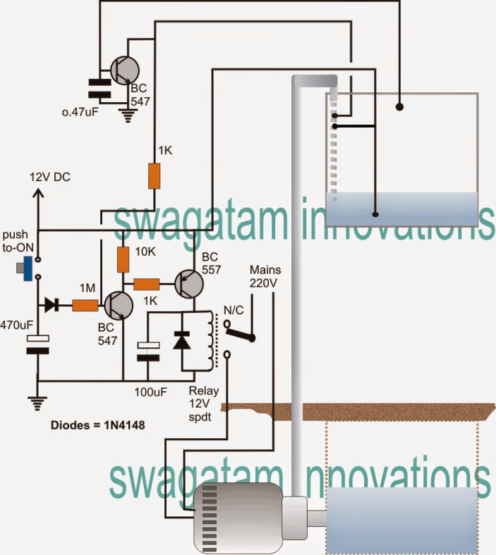
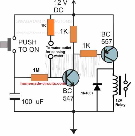
The circuit of the proposed underground water pump motor dry run protector can be understood with the help of the following details:
The circuit is powered with a 12V AC/DC adapter.
When the push-button is pressed momentarily, the BC547 transistor along with the BC557 relay driver stage is switched ON.
The 470uF capacitor and the 1M resistor forms a time delay network and locks the entire relay driver stage for some predetermined delay after the push button is released.
This delay interval can be adjusted by experimenting with the 470uF capacitor and/or the 1M resistor.
As soon as the relay activates, the motor is switched ON which instantly starts pulling water in the overhead tank.
The moment water inside the overhead tank pipe connects with its residual water, the submerged probe which is the positive probe gets linked with the probe that's introduced at the mouth of the pipe. This enables voltage from the lower probe to reach the base of the relevant BC547 transistor via the water, and the 1K resistor.
The above action now latches the relay driver stage such that even after the time delay lapses, the relay holds and sustains the operation.
Now the motor halts only under two conditions:
1) If the water level reaches the overflowing level of the overhead tank wherein the positive potential from the lower probe gets connected with the probe that's connected with the base of the upper BC547 transistor.
The condition switches ON the upper BC547 which instantly breaks the relay driver stage latch and the motor stops.
2) If the water inside the underground tank dries out, which obviously stops the water link inside the overhead tank pipe and breaks the relay driver latch.
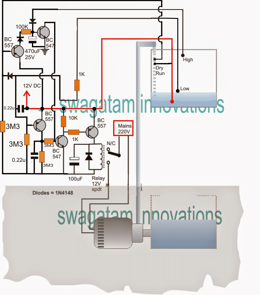
An Automatic version of the above sump motor controller with dry run protection system may be witnessed below:
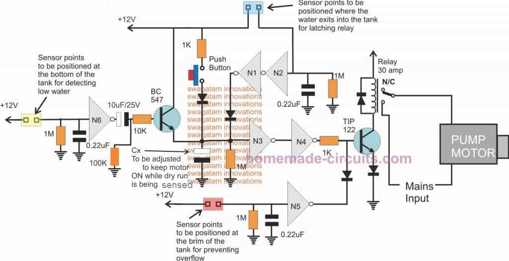
Using Logic Gates: Design #2
A fully automatic version can be also built using 6 NOT gates from the IC 4049 as shown below, this configuration can be expected to work much more accurately than the above transistorized version of the automatic underground submersible water pump dry run protection circuit.
Feedback from Mr. Prashant Zingade
Hello Swagatam,
How are you? Your Idea and logic are awesome. hats-off to you. I tried IC4049 version, It is working fine except one issue.(I done one modification base on your previous design and it is working now).
I am facing one issue in IC version like when we put it on auto mode, dry run function is not working. Please see attached simulated video file.
Case 1: I observe If water level reach below bottom level relay will on pump but it fail to sense dry run and pump will continue to on.
Case 2: In manual operation it works perfectly. Excuse for any typo.
Warm Regard
Prashant P Zingade
Solving the Circuit Problem
Hello Prashant,
Yes you are right.
To correct the situation we will need to connect the output of N6 to the base of the BC547 through a capacitor, you can try connecting a 10uF here.
Negative of the capacitor will go towards the base.
But the problem is, this operation will activate the system only once, and if water is not detected then the system will switch OFF the relay and remain switched OFF permanently until it is activated manually using the switch, and until the yellow sensor comes in contact with water yet again. Regards.
Update
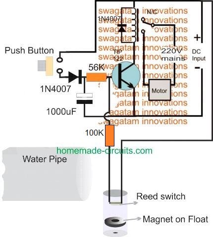
Dry Run Protection for Motor Reed Switch: Design#3
The following diagram shows an effective dry run protection that can be added to the pump motor, in cases where water is unavailable in the tank and no water flows out from the pipe outlet.
Here the push-button is initially pressed to start the motor.
The 1000uF capacitor and the 56k resistor acts like a delay off timer and keeps the transistor switch ON even after the push button is released so that the motor keeps running for a few seconds.
During this time water can be expected to flow out from the pipe outlet, and this will fill up the small container introduced near the mouth of the hose pipe. This container can be seen having a float magnet and a reed switch relay arranged inside.
As soon as water starts filling inside the container the float magnet quickly rises at the top and reaches at a close proximity to the reed relay, latching it ON. The reed relay now feeds a positive voltage to the base of the transistor ensuring that the transistor gets latched up and keeps the motor running.
However in an absence of water, the reed relay feedback is unable to turn ON, which causes the motor to shut down once the delay OFF time elapses after the predetermined amount of delay.
Dry Run Protection without Reed Switch and Magnet
If you are not interested to use a reed switch or a magnetic float sensor arrangement, you can simplify the above design as indicated in the following diagram:
When the push button is pressed BC547 and the BC557 conduct to operate the relay. The relay switches ON the connected pump motor. The pump motor begins attempting to pump water through the pipe.
If water is available, it flows through the pipe outlet and bridges the positive supply with the base of BC547. This causes the whole circuit to latch through the water contact, so that the pump keeps pumping water continuously.
However, in a situation where water is dry or unavailable, no water is able to feed the base of the BC547. Therefore BC547 remains switched ON only for a period determined by the charge on the 100uF capacitor.
The 100uF capacitor and the 1 M resistor decides for how much time the BC547, the BC557, the relay and pump motor can remain switched ON.
As soon as the above time elapses, the circuit automatically switches OFF itself and the pump motor and saves the motor from burning due to a dry run situation.
Current Sensed Dry Run Protector Circuit: Design #4
In the above ideas the circuits mostly depend on detection of water which makes the designs a little outdated and cumbersome.
The following idea unlike the above depends on load sensing or current sensing for executing the dry run protection feature.Thus it is contactless, and does not rely on having a direct contact with the motor or water.
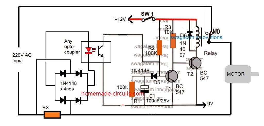
Here, the two transistors along with the associated components form a simple delay ON timer circuit. When SW1 is switched ON, the transistor T1 remains switched OFF because of C1 which initially grounds the base drive of T1 coming via R2, while C1 charges.
This keeps T2 switched ON and the relay also switches ON. The N/O of the relay switches ON the pump motor. Depending on the value of C1, the motor is allowed to run for sometime. In case there's no water, the motor runs unloaded with relatively low current passing through RX. Due to this RX is unable to develop sufficient potential across itself, which in turn keeps the opto-coupler LED switch OFF. This allows C1 to get charged fully unhindered during the stipulated period.
As soon as C1 is fully charged T1 switches ON, and this switches OFF T2 and also the relay. The motor is finally shut off protecting it from a dry run situation.
On the contrary suppose the motor gets the normal supply of water, and starts pumping it normally, this instantly loads the motor causing it to consume more current.
As per the calculated value of the resistor Rx, this develops sufficient voltage across it to switch ON the LED of the opto-coupler. Once the opto is activated C1 is inhibited from charging, and the delay ON timer is disabled. The relay now continues to supply the 220V to the motor allowing it to run as long as water is available.
Another Simple Motor Dry Run Protector Circuit: Design #5
Here;s yet another idea which explains a very simple overflow controller circuit which is able to implement and restrict overhead water overflow as well as dry running of the pump motor.
The idea was requested by Mr. S.R. Paranjape.
Technical Specifications
I came across your site while searching for Timer circuit. I am very surprised by seeing how much one individual can do!
I refer to your write up of Friday 20, 2012.
I have a similar problem. I have a designed a circuit, which appears to work on breadboard.I want to start pumping only if there is a need in upper tank and lower tank has enough water. Further if water in lower tank goes below certain level while pumping, the pumping should stop.
I am trying to find a way for satisfying my last condition.
I want to start this circuit manually and when the circuit stops pumping action, it should also nullify my start action. This will stop the total operation of filling the upper tank.
Somehow I feel that combination of two relays( outside the circuit) in ON/Off part of total project should work. I am unable to figure how so far.
The above drawing may express what I want.Project/circuit is powered by the outer source. The output(that is used to stop umping) from the circuit should open the outer source, which was activated manually.
I hope you will excuse me in taking this root to pose my problem. If you find merit in my problem, you are welcome to put it on your blog.
I am attaching the circuit that I have devised.
As an introduction to myself- I am senior person(age 75 years) and has taken this as hobby to use my time interestingly.I was Professor of Statistics, University of Pune.
I enjoy reading your projects.
Thanking you
S.R.Paranjape
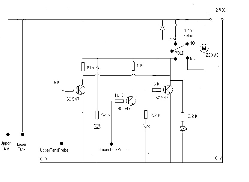.bmp)
The Design
I appreciate the effort from Mr. S.R. Paranjpe, however the above design may not be correct due to many different reasons.
The correct version is shown below (please click to enlarge), the circuit functioning may be understood with the help of the following points:
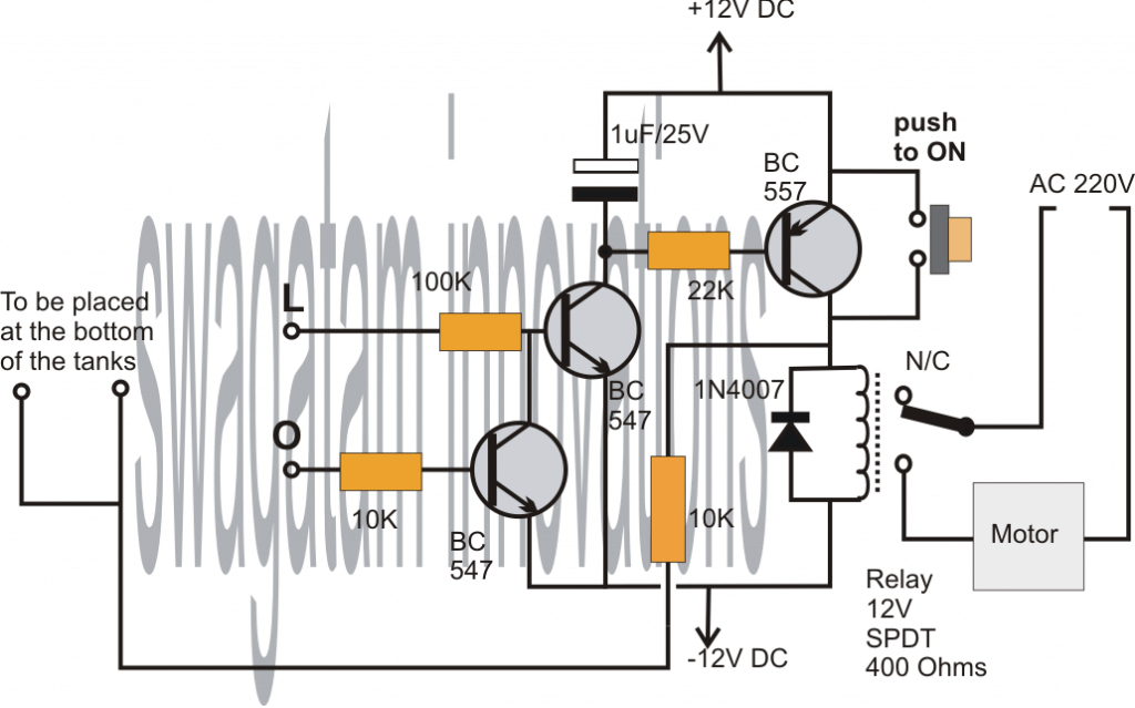
The point "L" is positioned at some desired point inside the lower tank, which determines the tanks lower water level at which the motor is in the permitted zone of operation.
The terminal "O" is fixed at the topmost level of the upper tank or the overhead tank at which the motor should halt and stop filling the upper tank.
The basic switch ON sensing is done by the central NPN transistor whose base is connected to point "L", while the switch OFF action is performed by the lower NPN transistor whose base is connected to point "O".
However the above operations cannot initiate until the water itself is supplied with a positive potential or voltage.
A push-button switch has been included as requested for facilitating the required manual start function.
On pressing the given push button momentarily, allows a positive potential to enter the tank water via the push button contacts.
Assuming the lower tank level to be above the point "L" allows the above voltage to reach the base of the central transistor via the water, which instantly triggers the central transistor into conduction.
This triggering of the central transistor switches ON the relay driver stage along with the the motor, and it also latches the relay driver transistor such that now even if the push button is released sustains the operation of the circuit and the motor.
In the above latched situation, the motor halts under two conditions: either the water level goes below the point "L" or if the water is pumped until the overhead tanks upper limit is reached, that is at point"O"
With the first condition, the voltage from the relay driver collector is inhibited from reaching point "L" breaking the latch and the motor operation.
With the second condition, the lower BC547 gets triggered and breaks the latch by grounding the central transistors base.
Thus the overhead water level controller circuit is allowed to remain operational only as long as the water level is at or above point "L" or is below point "O", and also, the initialization is solely dependent on the pressing of the given push button.
IC 555 Dry run protection circuit
The dry run protection can be added to an existing IC 555 based controller circuit, a shown below:

The dry run function in the above design works in the following manner:
When the water level goes below the "low level" probe, causes the positive potential to be removed from pin#2 of the IC. This in turn causes pin#2 to go low, which instantly turns pi#3 high.
This high signal passes through the 470uF capacitor swithing ON the relay driver stage, and the pump motor is switched ON.
The relay driver and the pump remains switched ON only as long as the 470 uF charges, this may be for around 3 to 5 seconds.
Within this time span, if the pumps starts drawing water will allow the water sensor connected with the blue wires to be bridged by the pumped water.
The associated BC547 will now get the base bias and begin conducting, bypassing the 470 uF capacitor. This will enable the relay driver BC547 to conduct freely until the full tank level is reached.
On the other hand, if suppose there's no water, and the pump runs dry, will be unable to bias the upper BC547, and eventually the 470 uF will be charged full blocking any further base current to the relay driver stage. Due to this relay will be switched OFF preventing the dry run condition.
Hello sir
Hello Dhananjay,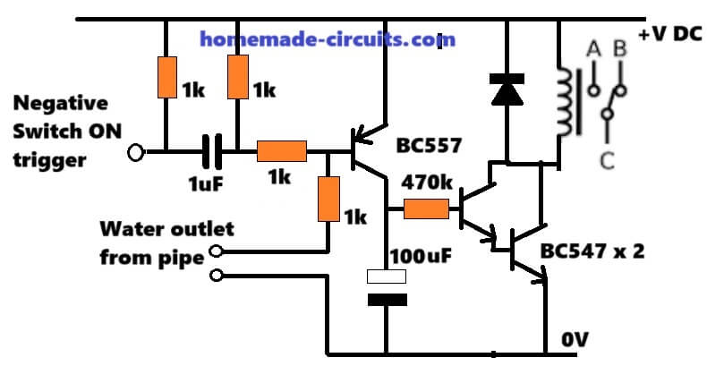
for your specific application you can try something like this, and customize it as desired:
" rel="ugc">
Sir
What is the purpose of negative switch on trigger?
You will have to activate the relay for some moment of time so that the motor can run and detect water. For this momentarily switching ON of the motor this triggering will be required. After triggering if the water is detected by the dry run probes then the transistor will “latch” and the motor will continue to run as long as water remains available…and then switch OFF automatically once water stops coming…
Respected Sir,
That’s great of you sir you had specially designed for me.
Grounding momentarily will work or will have to give negative voltage at that point.
I can ground it continuously as I had connected it to relay of motor on.
You are welcome Dhananjay,
Yes, it just needs to be grounded and afterwards removed.
You can connect it with the collector of T1 " rel="ugc">in your attached diagram
Hello sir
I think diagram was not attached.
I think the diagram was not attached.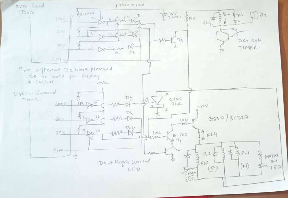
Are you referring to this diagram which you had sent previously?:
" rel="ugc">
Sir
The transistor BC547 is connected to a relay for shutdown of motor.
But the connection of bc557 refered in your dryrun circuit is attached to Vcc via a water flow. Whereas I want to connect it to ground using bc547 with 2.2 meg ohm resistance connected to Vcc and not to ground.
Dhananjay,
Yes I have understood the requirement, but still aa diagram of the whole thing would make my job easier.
Your diagram is still not uploaded. Make sure your diagram is in jpef, or png and below 2MB, so please reduce the image size and compress it before sending.
Or you can upload it to some other online site and provide the link here, I will check it out.
Yes
In the right corner top side the bc547 is connected to relay.
Ok, let me check it….
The circuit diagram is attached herewith theis is modified to your dryrun circuit and the new change is that I want to connect bc547 in place of bc557 with 3.3mohm resistance connect to supply and not to ground else circuit will be as it is.
Respected sir
I had used your water level controller circuit of triac control one. But I want to add a dry run sensor to that circuit but the problem is that the common terminal is ground and not Vcc. All your dryrun circuits are working on Vcc as common as I connect the circuit thd main led and other circuit is not working as the Vcc from dry run and ground common which is alredy in tank gets connected through water.
Can I use Bc547 in place of BC 557 and modify the circuit, will it work?
Please help
Hello Dhananjay,
In your design where do you want to connect the BC547 collector of the attached diagram? To make the attached circuit respond to negative common, we will have to change both the transistors, that is why I want to know where the collector of the BC547 is going in your design….
hi sir,
I have tested the circuit with motor in that I faced an issue. when I touch upper BC547 Base wire thru the hand motor started jerking and when water touched upper transistor base wire not the terminal then also motor started jerking. I think induction is more how to overcome this?
Hi Sathish,
please try connecting a 0.22uF, or a 0.47uF between the base and the ground of the upper BC547 and check the results….
hi sir,
i have tried the given LED indication circuit everything but updates required on below.
1. when no water flow detected the green LED taking long time turn off but relay turned off early it should be same time.
2.when tank full at high level indicator organe LED only to be turned but for me yellow and orange both are turning on. Yellow to be turned off only when is turned off not all at high level indication l.
Hi Sathish,
With reference " rel="ugc">to this diagram, here are the possible solutions for your questions:
1) Please connect a 3V zener diode or a 6V zener diode in series with the green LED, anode of the zener diode will be towards the collector of the lower BC547.
2) The only solution for this to remove the yellow LED entirely, because it is not serving any purpose.
hi sir,
As per new diagram when no water flow then yellow LED turned on but at the same time high level sense RED LED also turned on. This is not expected in our dry run scenario.
Sathish, yes that’s the correct response from the LEDs in the following diagram: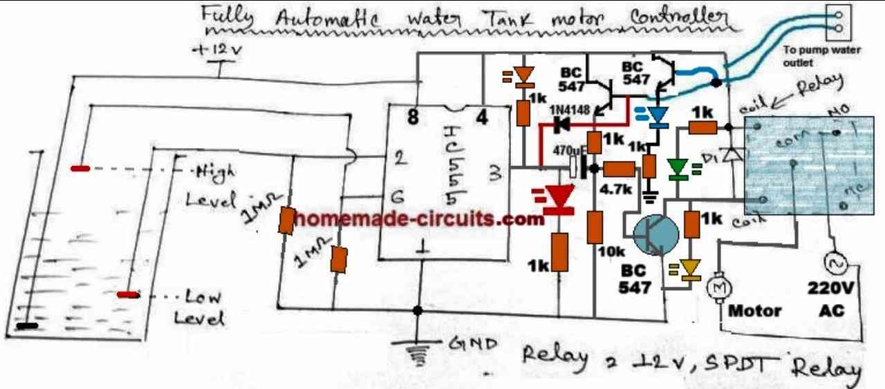
" rel="ugc">
The yellow LED indicates that the relay has been turned OFF (because there’s no water detected by the dry-run sensor and the 470uF is fully charged)
The RED LED indicates that although the relay is turned OFF, the water in the tank is below the LOW level.
Hi,
Update: After 4 months of usage, I’m pleased to report that the 555 dry run protection circuit is working perfectly without any issues. I’d like to extend my gratitude for the prompt response and making this project a success.
Thank you for the update Satish, Glad to know the circuit is working successfully for the last 4 months. All the best to you.
hi sir,
pls share the updated diagram url or specify the article section because am unable to find it.
thanks
Sure, here is the URL of the new diagram:
" rel="ugc">
I have assembled the design 1 circuit where in the timer is controlled by 1M resistor and 470micro farad capacitor. It takes long time to to de energize the relay. My requirement is only 10seconds. This i have resolved by connecting 18k resistor in parallel with the capacitor. The other problem is the relay voltage is gradually fading and at particular voltage the relay is cut off. Pl suggest how fading of relay can be avoided and cut off should take place instantaneously.
Hi, thanks for trying the first circuit.
The relay voltage will get weaker and ultimately turn off if the BC547 near the push-button does not remain latched by the feedback voltage coming from the header tank water flow from the pipe. In the first diagram you can see the feedback voltage coming from the header tank to the base of the BC547 through a 1k resistor.
Please verify whether the BC547 base is getting this feedback voltage or not.
To ensure that the relay trips off quickly when the header tank is full, please attach the positive supply probe close to the upper sensor probe of the tank. Keep the positive supply probe at around 1 inch distance from the upper probe.
Thanks for the explanation. The transistor Bc 547 base is getting very good positive feedback through water out let pipe sensor and getting immediate latch. When there is discontinuity of water the realy de energize immediately and no problem. If you assume a situation after pressing the push button motor starts and no water then relay is held for few seconds and de energize due to absence of positive feedback through water. Such de energizing is only happening gradually may be due gradual discharge of timer capacitor 470mfarad. This weak opening may create arcing of rela relay contact as 230v motor is connected. Hope made the issue clear.
Ok, now I understand what you are trying to say.
In that case the only way to ensure that the relay deactivates sharply is to put an LM393 comparator IC or a 741 opamp IC between the two transistors.
Let me know if you are able to configure it yourself or not.
Yes I can configure. The situation I have told may be a rare case. I will try as per circuit and difficulty if any I will go as per your suggestions. Thanks for your guidance please.
Ok, great, let me know if you have any issues with the implementation…
Thank you sir
hello swagatam
thanks for the knowledge and idea given on design 4
it has really opened up my mind
but how can create one using an arduino uno r3
your response will be highly appreciated
Thank you Nathan, Glad you found the post helpful.
However, since my Arduino knowledge is not good, it can be difficult for me to provide an Arduino version of the circuit.
Nevertheless, an Arduino design could be an overkill for this simple concept.
from Kesavachandran
hello Swagatam many thanks for your current sense circuit (Current Sensed Dry Run Protector Circuit: Design #4). I again thank you for your quick response. But one doubt. In the circuit I cannot see C2. Also kindly note the value and wattage of RX. Regards
My pleasure Kesavachandran,
C2 was mistakenly written, actually it should be be C1, I have corrected it now, thanks for pointing out the mistake.
RX wattage can be calculated using the following formula:
Wattage = 1.2 x Motor current with load
thank you mr. swagatam for your reponse.
Kesavachasndran
You are welcome Kesavachandran.
Once again I thank you sir for your reply
You are welcome Kesavachandran
Electrical current sensing circuit for avoid dry run submersible motor
Now a days there is a protection sensor in submersible motor Panel. Can you tell me what kind of circuit thay are using ? Swagatam please . With regards
Hi kesavachandran, I Can’t seem to figure out that circuit, if I happen to get one will surely let you know about it.
Thank you sir for your prompt response
You are welcome Kesavachandran!
Hi, Swagatam!!!
Design #4
Question: maybe it is necessary to put a resistor of about 2-10 kilo ohms between the diode bridge and the optocoupler?
May I use 4N35 optocoupler in this circuit?
Thank you for response.
Respectfully,
Jorge
Hi Jorge, yes you are right, may be a 100 ohm resistor should be enough. You can use any opto coupler which works with an LED and transistor internally, 4n35 will also do!
@Swagatam! Can PC817 be used in place of 4N35?
Thanks for your attention!
Hi Dang, yes, you can use PC817 in place of 4N35
hi,
i have tried 555 IC controller low/high level detection working perfectly but when no water flow still motor remains on. but it should off when no water flow right.
That should not happen, because once the 470uF capacitor charges up, it will cut off the base bias for the BC547 and turn off the relay.
Please remove the dry run (upper BC547 section) completely and check again, if the motor keeps running then the problem could be with the 470uF capacitor at pin#3 of the IC 555, let me know how it goes…
hi sir,
what is the recommended capacitor voltage ? for 470uf.
Hi Sathish, if the 555 operating voltage is 12V then the capacitor voltages can be 25V.
hi sir,
correct as you said after removed the upper BC547 no supply to relay. what could the issue any idea?
So, now, do you mean when the low water level is detected the relay is turned ON for a few seconds and turned off, right? Please let me know…
hi Sir,
Relay not turned on for few seconds also it’s completely not working. after install the upper BC547 water controller working fine concern is water flow sensor not working. any other circuit for 555 ic circuit for flow sensor.
Satish, short circuit the 470uF capacitor terminals and check again, if still it doesn’t work then something may be wrong with your circuit.
You must first make the circuit work without the upper BC547, once the low level, full level detections work normally only after that we can proceed with the dry run integration.
hi sir,
Thanks for your efforts and timely reply.
This worked perfectly, including dry run protection. I need to add two more LEDs apart from the existing. I can take the existing circuit LED-1 for motor On. Same like that, I need another LED-2 for the motor off. And LED-3 for dry run if motor on but there is no water flow, then in case LED-3 is on. Each LED’s to be worked on their specific function.
That’s great Sathish,
Glad it is working now!
Please check the updated diagram in the above article, I have added all the necessary LED indicators in it, you can keep or remove them as you want.
hi sir,
after changing the IC low level and high level along with flow sensor working now. But what happen when water flow is there capacitor keep on charging and discharging during the time low level and high level working perfectly. when no flow is there capacitor got charged full and relay the turned off. But the problem here is capacitor is not allowing relay to turn on even in low level as next attempt i tried with power off and on also still not worked after short the capacitor manually allowing relay to on. Any solution on this.
No problem Sathish, i will make sure you succeed with this project.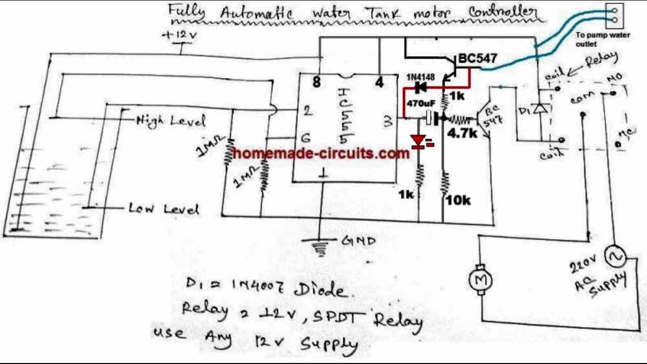
Please try the following modifications in the design:
" rel="ugc">
I have done the following modifications in this design:
1) added a 10k on the negative side of the 470uF capacitor so that iit can discharge effectively whenever pin#3 of the IC turns low (when water high level is detected)
2) moved the 1k resistor from the collector of the upper BC547 to the emitter of the upper BC547, to ensure proper safety for the transistor.
3) connected the anode of the 1N4148 to the base of the upper Bc547 to ensure effective turn off for the transistor whenever high water level is detected and pin#3 of the IC turns low.
4) Reduced the lower BC547 base resistor to 4.7k to enhance the turn ON capability of the transistor and the relay.
Let me know how it works….
Sir,
Greetings..!!
This is not a mail to pointing a fault or critisise you.This is for appreciate you for your effort to give us industry standard circuits to hobbyists around the globe.all were very nice and work properly at first time morover every doubt you clear through mail as express as possible.Your circuit of water level indicater with 4049 successfully install at 6 of my relatives house past 2years all of them working fine up today.Anyway appreciate great effort.Keep post more circuits.Thanks alot…!!!
From Kerala
With love
Sison.c.s
Thank you so much Sison, I appreciate your genuine feedback. Please keep up the good work!
Sir,Regarding the #4 idea how can we calculate the current sensing resistor Rx?
to different loads.Appreciate if you could explain with 1hp motor as example.Thank you.
regards.
SISON
Kerala
Sison, the formula is
RX = 2.5 / Normal Motor Current while it is pumping water
Hi! What the power (WATT) of RX, how I can calculate it?
In this calculation (RX = 2.5 / Normal Motor Current while it is pumping water) current in amp, milliamp value?
Thank you, sir!
Current will be in Amps.
Wattage = 2.5 x Normal Motor Current while it is loaded and pumping water.
Can we replace RX with current sensing coil? Swagtam. I am thinking of Opamp and an inductive current sensing coil.
Any advice Swag?
Hi Dang, yes that may be possible, if the current sensing coil can produce sufficient voltage to operate the opto coupler.
The barzer will ring just when the pump is off for a dry run. From which I can see that there is a problem with the pump. So please tell me how to set this buzer?
Which circuit are you referring to?
Thank you for quick answering! If you don’t mind- please explain: at the over head tank, where the lower prob carries 12 volt DC, and whenever it completes cct with pin 2 and pin 6 at a time( both are receiving12 v dc), the relay not going off! 1M resistor getting heated. Please help me. Thanking you.
You are Welcome! A 1 M resistor has a very high resistance and can never heat up, even if you connect it with 220 V mains AC. So it seems something’s may not be correct with your resistors, because it is impossible for a 1M to become hot.
Please check the probe actions by manually connecting the 12V with the two sensor probes, alternately. This should set/reset the IC output ON/OFF alternately
Once the actions are confirmed make sure that the 12V supply in water is held close to the two sensing probes so that the sensing probes are able to detect the 12V supply through water optimally.
Dear Sir, I have tried your circuit with dry run along with 555 ic, but the relay not operating as the water level goes high or low. Only the relay being operated- for dry run! What is the function of 470 up electrolytic capacitor, as there is ac current is absent? And output of pin 3 of 555 being blocked. As a result relay driver not functioning. I’m not an expert. Please help me to build it. Thank you.
Hi Sujit, try operating the circuit by touching the probes manually with the positive line, and check whether the relay operates or not. If the relay operates then it means the water is conducting the 12V supply to the respective probes….in that case try placing the positive probe very close to the pin2 and pi6 probes, so that when water reaches these probes, the 12V positive connects with the sensing probes adequately.
The 470uF is a timing capacitor which allows the relay to operate for sometime until the 470uF charges fully then the supply to the transistor base is blocked by the 470uF. In the meantime if the pump starts pumping water the dry run transistor starts supplying the base current to the transistor so that the relay continues to remain switched ON
Hi Swagatam,
I want to put LED indication for overflow and dry run cutoff in IC 555 circuit, where can I place it ?
Hi Dipak, for the tank full indication you can put an LED between the positive and the pin#3 of the IC, via a 4k7 resistor.
For dry run indication you can put an LED in series with the upper BD547 base wire. If this LED does not light up after a few seconds and the relay switches OFF then it will indicate a dry run shut down.
Thanks Swagatam for prompt reply, LED for tank full indication is fine but any other idea for dry run indication with LED “ON” condition where I can visually see from the distance that the pump is stopped due to dry run.
Hi Dipak, there’s no other easy idea to monitor the dry run except putting an LED in series with the upper BC547 base…
Hi Swagatam,
Hope you are doing good.
I have tested your IC 555 based circuit in my table. It is working but there is a minor issue is that when dry run cut, the circuit doesn’t reset (even doing power off and on after a while ) unless I short the capacitor (to discharge). Could you please tell me how to solve this issue. Shall I provide a push button in parallel to the capacitor (to discharge) so that the circuit can be reset manually.
Please, awaiting for your reply.
Regards,
Babu Yousuf
Hi Babu, I think you can apply the following trick….take a BC547, connect its collector with the positive side of the cap and emitter with the negative side, and then connect the base of the transistor with the positive line via a 0.22uF series capacitor
Well i missed to mention this i have put a 2.2 K resistor at the base of bc547 resistor connected to blue wire. we we cnnot give 12v directly to base and with high current transistor may burn up. so thats obvious .
That is not related to the issue. The water itself has a resistance of more than 5k at an inch distance, and the emitter already has a 10k in series the transistor can never blow.
Even with 2.2k resistance the 12V will keep leaking from the emitter to the base of relay transistor.
The +12V should be taken from the pin3 to solve this issue….not from the supply line.
IC 555 Dry run protection circuit
This has a Flaw. When the leve is above HIGH and the motor is drawing current following happens
output at PIN 3 is low. However since the motor outlet sensor (blue wires) would still be shorted hence the capacitor Bypass transistor BC547 base will still be on Bypassing the capacitor and inturn turning on the BC547 connected to relay and hence even though the water has reached HIGH the motor would not stop.
So there needs few correction.
1. the 1k resistor connected to collector of transistor and 12v supply needs to be connected to Pin 3 and collector.
also the we need to have a Base emittor Resistor connected to the Transistor connected to relay without without which the motor will not stop running (This is due to capacitor which cahrges through the LED from the BC547 which is monitoring pump output)
You can see a 1N4148 diode placed between the emitter of the upper BC547 and pin3. this diode will sink the emitter voltage to pin3 logic low. But a 0.6V may still be present towards the base of the lower BC547…this can be simply corrected by adding another 1N4148 in series with the emitter of the lower BC547.
If we follow your idea of connecting the collector of the upper BC547 with pin3, then even though pin#3 will be logic low but the base/emitter of the upper BC547 will keep passing current to the lower BC547, keeping the relay permanently ON.
A base emitter resistor for the lower BC547 may not be required since a logic low at pin3 will effectively ground the base, unless the IC 555 is a low quality one and has some serious offset voltage.
…Your idea can be used if the blue wire positive is also taken from pin#3
I have tried having another 4148. It doesnot work . i had tried it myself with few combination.
when we try to implement such circuits at home we arent sure of the quality of components we get but its always safe to take in to consideration. just by having a resistor at bottom BC547 it worked exactly as intended and the relay want on permanently but only for RC time period. BE resistor bypassed excess current .
A diode at the emitter of the relay transistor will definitely keep the relay switched OFF, if it is not working for you then you must investigate from where the switching potential is coming from?
It may not work if you apply your idea of connecting the base and 12V of the other BC547 connected with water and collector with pin3, since it will keep leaking the whole 12V from water via base emitter of the transistor
Hi Swagatam,
Hope you are all doing good.
Please do let me know most effective circuit for Automatic water level control with dry run protection. I have seen that more discussion on IC555 circuit. Shall I get the latest revised circuit from you ? I am using mono block pump and well water.
If possible, please send it to my email.
Thanks & Best Regards,
Babu Yousuf.
Hello Babu, all the circuits presented above are good, and can be adopted for the water level control application.
For dry run protection you can refer to the following post:
5 Useful Motor Dry Run Protector Circuits Explained
Dear Swagatam,
Appreciate and thank you sir for your reply and your time.
Can we modified IC555 circuit with 24V DC instead of 12V ? if it can be, what are the changes required to do in this circuit. How many A/mA transformer and wattage of resistors/diode and wire gauge (for sensor) to use ? Please advice.
Thank you Babu, you can use 24V for the relay coil only, rest of the circuit will need to be operated with a 12V, derived from a 7812 IC.
Hi Sir,
Wishing you and your family a Happy New Year 2021.
Thanks for your quick response. I think I will go for your IC555 circuit as it is with 12VDC (without 7812 IC as per your circuit). Hope I will give you my feed back at the earliest.
With Best Regards.
No problem Babu, wish you too a Happy 2021.
Hai Sir,
I am Philip, I want to control my water pump motor automatically with dry run protection. now I am using BC548 transistor an four flot switches for the purpose.it is working very good condition but the problem is it have no dry run protection so many times motor become hot and O ring burning happened. so I am trying to make another circuit and finally find out your site and tried your IC555 circuit it is working but dry run protection not working then again tried your circuit using transistor BC547 and BC 557 but not working. I have a doubt that in your first design ( Design No.1) you mention earth point in two places 470mf cappasitor and BC547 emitor. But in fully automatic version the earth point is only in capacitor point no earth connection in relay point and other emitter points is it correct, please help me to make this circuit , or give some ideas for this purpose
Thankyou Sir
Hi Philip, all the circuits mentioned will work, but they will need to be done step-wise and stage-wise with correct understanding and adjustment of the different components. A few resistors may need to be adjusted slightly for proper results. The current passing through the water to the various sensors must be checked and correctly optimized for getting perfect results. If the sensors do not get proper current then the stages will not operate correctly. All these must be tested on a workbench with sample water content in glass or bowls. Only NPN BC547 need negative line connections, PNP BC557 do not need negative connections their emitters need positive connections.
All your circuit ideas r excellent. I am going to try CD 4049 IC with dry run protection. Hoping that this will work good. Any ready made pcb is avlble?. For 555 if version where to connect push button to start the motor. With the request can we make pcb of our own? .
Shivakumar.
Glad you are enjoying the articles, however I am sorry there’s no PCB designed for these projects so far.
For the IC 555 circuit you can connect a push button between the positive line and the base of the upper BC547 transistor, through a 1k resistor.
Sorry, due to lack of time it won’t be possible for me to design the PCB.
Sir,
Before 4 years I made your circuit using IC 4049 and it was working perfectly except dry run and i contacted you and get some instructions. Now I am requesting you to design a WATER LEVEL CONTROLLER WITH DRY RUN PROTECTION Using Aurdiuno Uno (328P) because i saw one circuit with 328P and excellent working with minimum components.
Thank You
Sorry Hameed, I am good with Arduino so it can be difficult to design the mentioned circuit idea.
Thank you sir for replaying.
Now i am going to try your 555 ic water level controller circuit. So please leave a link for last updated 555 ic circuit with dry run protection
Thank you
Hameed, please refer to the last diagram in the above article.
Hay swagatham,
I need a help in logic waterlevel controller circuit, How to connect a led indicater for dryrun cutoff, and thanks for the project, it’s working without any problems
thanks a lot
Hi Ajith, I am glad it’s working! for LED indication, you can connect an LED from +12V line to N2 output, make sure to put a series 1K resistor with the LED. This will show when the water connects…
In the the same way you can add anther LED/1K across +12V and N3 output to show dry run cut off
Hi sir 555 based dry run production circuit is not working sir …pls give me one good dryrun automatic circuit sir
Thank you
Raaman..
Hi Raaman, it will definitely work, you will have to check the various points around the two BC547 transistors to make it perfect. Please let me know what results are you getting, and you must check it manually on table first before implementing it for the motor dry run…
I hope you have made the following design:
Thanks sir now it’s working fine.
But 555 ic and some times that 547 transister getting short..
I don’t know the reason.pls help me sir …all my customers asking dry run motor off mechines only
Iam assambled and selling decice circuit is only buzzer used for dry run.. pls give me good dry run production fully automatic circuit sir….thank you for your reply
Your’s
M.Raaman
Shinetech electronics.
Hi Raman, the IC may be getting damaged due to back EMF from the motor, please add the following protection to the IC:
1) Connect the supply to pin4/8 of the IC 555 through a 100 ohm 1 watt resistor.
2) Connect a 100uF/25V capacitor across pin4/8 and ground of the IC
3) Add a 1N4007 diode across pin4/8 and ground of the IC. Cathode will go to pin4/8
Please do this and check the response…make sure to use 12V supply Dc only.
Connect a 1N4007 diode across collector/emitter of the BC547 also. Cathode will go to the collector.
Thanks sir
Now it’s working fine..iam using ….SL100 for relay drive transister
and 2222 transister for dry run production.. thank you
Your’s
M.Raaman
Shinetech electronics
That’s great Raman, appreciate your feedback!
Can you post the complete circuit diagram with above modifications for dry run?
hi Swagatham,
one question – when the tank is full (relay is off, both Low and High in water), the 555 gets heated up and behaves eratically. Pls. suggest a solution. Thanks.
Hi Pradeep, it could be due to the back emf transient from the motor which could be affecting the IC performance.
To control this you can add the following snubber network:
Thank you Swagatham. i will try this and update you.
You are welcome Pradeep!
Thanks Swagatham. my 555 was faulty, i replaced with a new one. With dry-run, it works as expecte for my garden pump and i have not used the snubber. Thanks so much for your help.. and appreaciate you find time for helping everyone.. Take care. Thanks.
Glad to know it’s solved Pradeep, the pleasure is all mine!
hi Swagatham,
Am facing a problem with the circuit after it worked for around a month. I have sent to you a mail, could you pls. check and suggest.. Thank you.
Hi Pradeepkumar, Please explain your problem, I’ll try to help you, I did not find any email from you so far….
Can I use the dry run section(additional transistor, capacitor and diode) in the above circuit in bistable mode? I mean manual ON and Manual OFF circuit? I already tried the same but dry run section is not working at all. After triggered the pin 2 the relay is triggered but the relay is never off though I introduced the dry run section at pin 3. Please provide me the circuit.
If water is not detected at the base of the upper BC547 transistor then it will never conduct, and therefore finally the 470uF capacitor will get a chance to become fully charged. When the 470uF capacitor gets full charged the relay driver BC547 will switch OFF.
You must investigate why the above is not happening in your circuit.
For manual ON OFF, you can try the following concept:
https://www.homemade-circuits.com/set-reset-circuit-using-ic-555/
Thanks for quick reply. I added the additional dry run section to this circuit ( https://www.homemade-circuits.com/set-reset-circuit-using-ic-555/ ) itself. I added the components as same as mentioned once I press the button at pin2 the relay is ON but now the dry run wires are open so it should stop after 5 secs or so right? but this is not happening. For me this dry run section is not working at all. If I short these dry run wires together the relay is automatically switch ON without pressing the switch at PIN2. Please help me on this.
Yes you are right, the relay must automatically switch OFF after 3, 4 seconds if no water is detected at the base of the upper BC547 transistor.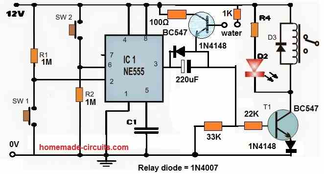
Please try the following setup.
Initially do not use the upper BC547 circuit. Test the relay operation without the upper BC547 stage.
Once the 220uF charges fully after around 3 or 4 seconds, the relay should quickly switch OFF.
" rel="ugc">
Thanks for the reply. It is working as expected now. Will it work if I connect long wires to the base of the transistor directly?? BTW can we add this dry run section to any of the circuit or only works with 555? One more thing that what to change in the circuit to achieve the below scenario.
**Once the relay is OFF in any case (either by OFF switch or by dry run scenario) the relay should be OFF until the power reset(switch off the device and on) which means it should not ON even if I press ON switch button once the relay is OFF.
Glad the circuit is working. With long wires also it should work, just make sure to add a 0.22uF capacitor between the base of the upper BC547 and the ground line. This will ensure all unwanted noise from the long wires are grounded.
The dry run concept can be used with similar set/reset circuits.
Once the relay is OFF, it will be reset under two scenarios:
1) If SW2 is pressed and again SW1 is pressed 2) If the base terminals of the upper BC547 is immersed in water.
However after SW2 is pressed the relay driver stage cannot be switched ON even if water is available at the base terminals of the upper BC547 transistor.
Once the relay is switched OFF (220uF fully charged) pressing SW1 repeatedly will not switch ON the relay.
Sorry, I really don’t understand the points 1 and 2 and the description. Can you show in any schematic if possible? Once the relay is OFF means it should OFF permanently until power rest to the whole circuit.
Once the 220uF capacitor is fully charged, the lower BC547 and the relay will switch OFF. The relay will switch ON again for 3 or 4 seconds, if the following things are done:
1) Water is introduced across the upper BC547 base terminals.
2) If SW2 switch is pressed momentarily and then SW1 is pressed momentarily.
3) If power is switched OFF for 5 or 10 seconds and switched ON again, and SW1 is pressed.
I got this…but if they is no dry run situation and the relay is OFF by pressing SW2 then in this case also I want to turn OFF the relay permanently and until and unless the power reset the device should not ON.
Yes, pressing SW2 should also turn OFF the relay even if water is present at the base of the upper BC547, because, once SW2 is pressed IC 555 pin#3 will become 0V. With pin#3 at 0V the upper BC547 emitter will be grounded via the 1N4148 diode so it cannot supply any voltage to the base of the lower BC547, so the lower BC547 will also remain switched OFF.
I know this but my problem is if I press SW2 relay is OFF and again if I press SW1 the relay is ON but it should not ON until complete power OFF and ON again then only SW1 should work. So how can I implement this?
No that may not be possible. If you press SW1 then naturally the relay will be switched ON. Without SW1 there will not be a manual way to switch ON the circuit.
If you want a total latching then a 555 circuit cannot be used you will have to implement a transistor latch circuit. It is possible using a transistor latch.
Ok. Thank you. Will try and update.
Hi swagatam!
I want to automate my piston pump so that it only runs when there is muncipal water in the inlet of the pump. Problem is that all the water sensors I searched can sense air flow too that I dont want. So I request you to suggest me any suitable sensor or any other technique for sensing water in the inlet.
Thank you.
Hi Muhammad, you can try the concepts presented in this article:
https://www.homemade-circuits.com/municipal-water-supply-sensor-pump/
I think my bc557 is faulty .
Its not working properly when i trouble shoot it alone.
If i use a not gate at base of 547
Does 547 become 557 sir?
Or other transistor i can use?
yes, you can use two NPN to replicate a PNP
I tried 555 version with dry run
It succeed in automatic water level control but failed in dry run protection.
Also i dunt get why blue wire is connected to emitter.
It started the motor when its under low level but didnt close off due to dry run after many seconds.
This is my circuit
s://drive.google.com/file/d/11GqLNGhYXf1lImdgnhQI61tMT5amqtrG/view?usp=drivesdk
I have explained the working of the modification at the end of this post:
https://www.homemade-circuits.com/underground-water-pump-motor-dry-run/
You will have to optimize the part values to make the circuit run as per the explanation.
The blue wire is connected with the ground line, which is also the emitter line of the relay transistor
or you can try an external circuit like this:
" rel="ugc">
Can i also know the reason of diode at base of 557?sir
it’s to ensure that the capacitor discharges only through the transistor and not through IC pin3
Im sry for complaining again and again sir but can u tell me a way to remove 557 and use other devices instead of it sir. With much respect
If dry run cut off power to ic 55 , pin 3 wil become low and motor wil turn off too. And the base of 557 get required negative signal and it wil turn on the 557 again. So the 55ic will regain its power and give out high at pin3 and motor will turn on again. Like this, im thinking confusingly sir. Can u pls explain and correct me who lack too much knowledge and think confused?
With lots of respect sir
Ihope u can help me im troubling with this project for over 2weeks now
Yes that’s correct, I’ll have to redesign it then…
im thinking about using 547 with a NOT gate at ase instead of 557 sir
will it work sir
but i dunt know if it will work because i dunt know the purpose of 4148 sir
I’ll redesign it and let you know how to proceed…
here’s the revised design, and should work as intended..
" rel="ugc">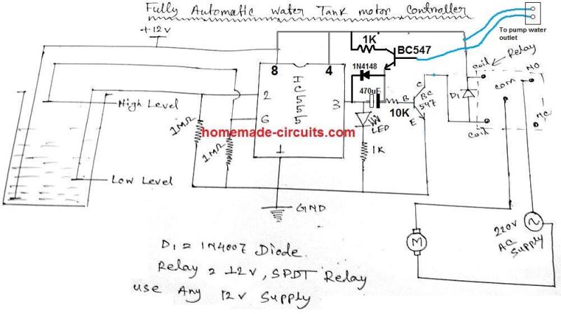
it was very nice to hav u helping me sir! This new revised circuit is also easy to understand and u also didnt use 557 as i proposed. Im vert greatful to u sir.
Sir as im not very familier with delays . May i know what i thought is right? Here’s wht i thought. The lower lvl water make pin 3 high . And tht charge capacitor. The capacitor only let current while charging.and during that time tht current make run the motor. After fully charge no more current and will turn off if there is no water at the water outlet. i hope its right sir
It’s my pleasure min!
Your assumption is absolutely correct. The circuit is supposed to work exactly in the same way!
Sir in this revised version may i know where 4148 prevents discharging to? Is it pin 3? Im thinking when it discharge it wil be to the direction from where it was charged. And tht is pin 3 . So is it ok to discharge to pin3 now ?sir
Hi min, the diode is not for discharging the capacitor, it’s to cut off the emitter voltage when the tank level reaches full level and the pin#3 become zero volt. Although the emitter would be well grounded through the capacitor even if the diode is not included, still for better accuracy I have included the diode.
Oh isee ! Sir
So when pin3 is zero it acts as a ground for emitter and the current from emitter will go to the ground and not go to other 547 to start the motor. Is tht it ?sir
Im going to test it tdy thank u so much sir
yes that’s right, however even if the diode link removed, the emitter would be still grounded through the capacitor due to opposite polarity of the capacitor, but adding the diode link makes it foolproof
Also,in my opinion sir, when water out let doesnt sense water, it will turn off the transistor. So there is no current from tht transistor but there may be a current from pin 3 to start the motor. But having a diode on tht path prevents it? Is tht also right? Sir
That’s correct, the only doubt is whether the trigger from the water will be strong enough to keep the relay ON or not
Dear Swagathem,
First i appreciate you for your simple desighn many of companies are produce commercially with micro controllers, but you provide us freely morover its working on first attempt.apprciate if you could provide whatsapp number or phone number.Also i have one quistion sir how long we can extend sensor wires?possible on first floor while unit on ground floor.Hope you will answer my quistion.Also need one buzzer activate while dry run .how to do?
Thank you Dear Sison,
Sorry, I discuss only from this commenting platform, I don’t use wattsapp for website queries.
You can extend the probes as much as you like, just make sure to add a small capacitor at the base/emitter of the sensor transistor, or across the gate input and ground, if a gate is used
Greetings…..
Sir,
When i assemble the circuit of 555 and 2nos bc148 circuit of water level controller with dryrun protection it work smoothly on breadboard.but unfortunately the dryrun not working when i assemble the circuit on pcb.But when i connect one 60kohm resistor between negative of electrolytic capacitor (470mfd)and powersupply negative on other end then work smoothly.i know this is not the proper method.why this happened?hope u will clear my doubt and do further modification also please give me a solution for false triggering too.there is no spilled flex on my pcb.its cleaned and dried.
Sisoncs, sorry , I cannot see any 470uF in the diagram? Can you please pin point the section.
Sir,
The revised circuit here with 555 ic and 2nos of bc547 trans.The 470mfd electrolytic capacitor is parrllel to 1n4148 diode.here is your link.
" rel="ugc">
Sisoncs, OK got it! The 60K or any high value resistor across the negative of the 470uF and ground line will facilitate proper discharge of the 470uF so that the next relay ON/OFF cycle can happen correctly. But I cannot see any role of this resistor with regards to dry run. Because the dry run is solely controlled by the current delivered by the BC547 emitter.
In design two any othet transistor i can use instead of tp122 sir?
I cant get tht transistor for now
you can try 8050 or 2N2222
In design 2 sensor points simply mean wire dipped in the water right? Not real sensors? Sir
yes, they are copper ends, tinned with solder.
design 2 diode are 4007 or 4148 ? Sir or both ok?
for relay 1N4007, rest all are 1N4148
s://drive.google.com/file/d/1-y1kFMk73NbmwzPP-0SEJCtEGz8U31Ky/view?usp=drivesdk
Sir i did automatic motor control with this 555Ic circuit? How can i modify this into dry run protection?
Kaung, You can try the following updated circuit:
" rel="ugc">
Thank u for designing this circuit sir
Is it also a delayed circuit? Sir
Thanks Kaung, yes the dry run is with a slight delay.
For 5seconds delay what capacitance should i use?
100uF near the push button should give 5 second delay
Can i use other not gate ic in design 2?sir
yes will do!
in design 2 feed back i saw that he is facing one issue but it was solved making a modification
do i need to do tht modification or can i jus use yr circuit diagram? i want to know if u hav updated tht diagram to fix tht issue
with respect from this newbie sir thanks
Yes it has been updated…the 10uF near N6 output is the updated part
can i know the specific capacitance for design 2 ?
as im still a student in electronics i cant estimate it
and i hav tried transistor version but not working may be due to my lack of knowledge or transistors malfunctioning.
so im going to try design 2 . so can i know cx written there to make a delay of 5second
For a newcomer it can be a complex circuit, so I’ll recommend building it stage-wise, initially keep the N5, and N6 stages aloof and disconnected. Once the central N1—N4 latch is confirmed then go for the N5 stage, and then finally the N6 stage.
For 5 seconds you can try a 470uF capacitor…or 220uF might also work…calculating accurately can be difficult, trial and error method is the quickest.
sir
only ic 4049 is recommended ? or can i use other not gate ICs?
Any NOT gate IC will work
I need a dry run protection system for a submersible deep well pump that works by sensing the flow of water through the outlet pipe of the pump. I mean to say the circuit should be based on flow-sensor, and turns the pump off as soon as it detects that the flow of water has stopped. I do not want the system to be based on level sensors or probes. I simply need to turn the pump off when the flow sensor that is installed at any point on the outlet pipe of the pump, senses that there is no flow.
You can try the following concept:
https://www.homemade-circuits.com/municipal-water-supply-sensor-pump/
ignore the probe and the connections.
use a small motor with propellers as the flow sensors, connect the motor wires across the 1K end and ground line of the circuit
after turning the pump on, the water takes few seconds to start flowing through the pipe. how would the transistor TIP122 be in ON state during that time? also, can you tell any other way, besides using a small motor with propellers, to sense the flow of water?
a reed and magnet arrangement can be used instead of motor,I will try to update the drawing soon.
ok. also please tell how the transistor would be in ON state at pump startup
I have updated the diagram in the above article
I have just come across this site with these circuits and wonder if you can help me….. I have a similar requirement.
I need a circuit to prevent a submersible bore pump (1100W) running dry, ie exhausting its water supply. I need the pump to shut off when the water level reaches about 1M above the pump intake, and start up again when the water level reaches about 3M above the intake. The pump body at earth potential would provide the common reference. The probes and associated wiring to the surface are already in place at those distances.
Any help you can give would be much appreciated. I can build circuits but just do not have the knowledge to figure the actual circuitry out. Many thanks in anticipation.
I’ll design it soon for you and let you know….
I have posted the idea at the bottom of this post
https://www.homemade-circuits.com/how-to-make-simple-water-level/
Dear Sir,
Please check your mail, I implemented that IC circuit and mail photos in the given ID, Please have a look sir and tell me the corrections.
Thanks & Best Regards
P G Ragavandir
Dear Ragavan, that would be impossible to check and implement…you must do it stage wise….first build only N3/N4, by connecting the associated parts along with the relay driver and the push switch stage.
once this is confirmed then go for the other gates one after the other and test them with sample water inside a cup…
so it has to be done in this way….and preferably do it on a veroboard not on bread board, because breadboard can be to messy and difficult to troubleshoot the connections.
Dear Sir,
Thanks for your reply, will do as you said sir
Best Regards
PG Ragavandir
Yesterday I build and install transistor based circuit. I am facing some issue. When water touch to wire (or Sensor) water pump misbehaving, it stop and start constantly (In short fluctuate constantly), also my mother notice that pump start and stop automatically. Please advise.
for the transistor version you will have to understand each stage and troubleshoot it yourself, it would be impossible for me to do it from here since there are many stages which may need careful adjustments.
by the way in the above comments you said you wanted to build the IC version and you also said you wanted star/stop type of control for your motor, so I am a little confused.
Thanks for you comment.
Can I try to increase value to cap of BC547(used to break latch/ used In OHT)
Just few day before I saw IC version. Previously I was working on transistor version, It is done now. I will try for IC version and let you know if any issue.
Can I have your Email ID ? so that I can share circuit diagram from which I created PCB
I'm taking about first circuit diagram. 3 transistor used.
OK but you cannot control a start/stop contactor box using the first circuit?
my email is
admin
@162.240.8.81
if you increase the timing capacitor that might affect the dry run protection in case water is not available….because with increased delay the motor would keep operating for longer period of time before switching OFF
One quick question. Can we use IC version with submersible pump. If yes then how , what are changes need to be done.
Submersible control unit have RED and GREEN button. Green use to start pump and red used to stop. In such case where to fit circuit.
I have answered your question, please refer to the previous comment….
Thanks, I will try this.
Its regarding IC version.
If it is fully Automatic(i mean to say pump will when water level go below low level and stop at high level) then why push button is used.
Correct me if I am wrong.
the push button start is an added feature which allows the user to start the motor anytime he wants, without depending on the lower level detection.
One more quick question. How this IC version to be used in submersible pump. (There is stop and start button on board)
for start stop contactor operations, you may have to employ the following concept
https://www.homemade-circuits.com/2015/09/automatic-submersible-pump-contactor.html
or the following
https://www.homemade-circuits.com/2015/09/borewell-motor-pump-starter-controller.html
I am talking about IC version.
1)What is value of cap connected to emitter of BC547 (OR positioned to left of N3).
2)Please correct me if im reading circuit wrongly . From circuit diagram I think N1 and N2 (pin 1 &2), N3 and N4 (Pin 3 & 4) connected to each other ?Right
the cap value is for the delay effect when the push button is used…it will need to be experimented, it could be around 22uF to 47uF
input of one gate is connected with the output of the other gate for N1/N2, N3/N4
Dear sir,
Thanks for your reply, I tried doing first and second circuit but I failed, so only I asked you for bread board model. (I can understand you will be busy sir so only I requested if possible.) I Will try sir. So kind of you sir.
Best Regards
PG Ragavandir
Thanks Ragavan, it is your learning phase, so you may have to go through some failures, all do…I am sure soon you will be able to overcome the failures and begin succeeding with the projects. all the best to you
Dear Sir,
Thanks for your positive words and faith on me.
Soon will overcome sir.
Thanks & Best Regards
PG Ragavandir
my Email-ID is vijayragavandir@gmail.com
Thank you Ragavan, Wish you too a Very Happy New Year!!
I am sorry due to lack of time practical guidance may not be possible, however if you any specific queries I can help you to solve it here
Dear Sir,
Wish you a very HAPPY NEW YEAR sir, Stay happy always……
Sir if possible can you please give this circuit with fully assembled in Bread Board ( practically) please, as I'm beginner I can understand in that easily.
Thanks & Best Regards
PG Ragavandir
Sir,Thank you for your reply, I am waiting for you to send the IC version circuit soon.
sure…It might take a little time so kindly bear with me…
I have updated it in the article, you can check it out
Sir,Fully Automatic version circuit is not working,i tryed 11 times on 6 boards,if any modification in this circuit please tell me sir,How to solve it? Thank you
Dimu, it will not work unless you confirm and optimize each stage separately on table using sample water in a small container to simulate tank water,and then integrate each of the stages one by one for the final outcome….
Since it is a transistorized circuit it might be be little inefficient and require some serious tweaking to make it work perfectly…..
if possible I'll try to update an IC version of the same which will not require much adjustments and can be made to function quickly…
Sir
I have seen the blog "An Automatic version of sump motor controller with dry run protection system" in https://www.homemade-circuits.com/2013/07/underground-water-pump-motor-dry-run.html
Can we put a switch in the circuit to run motor at any time in manual mode (water may not reach low level) and auto stop motor when tank is full.
Hope you understand & Thanks
Pls. reply: amarendra_co@yahoo.com
Amarendra, you will have to momentraily cut the 12V supply which goes to the upper tank in order to initiate the motor…this can be done by a push-to-OFF kind of switch connected in series with this 12V line.
but please note that this circuit will need to be perfectly optimized in order to make it respond to the various water linked sensors…otherwise you may find it difficult to get the expedited resulst from it.
check carefully, you will find it at extreme left of the design
sir
what if the same motor is used for irrigation ie there is no any overhead tank and a rubber pipe is inserted in water pump mouth then how to detect if motor is running dry or not
Rahul, you will need to place the sensor probes at the mouth of the pump pipe….as long as water is coming out from here, the circuit will stay switched ON, but the moment the pump stops throwing water, the pump will be switched off….preventing its dry run
I tried on simulator software. It start on push button. But it is not stoping replay when water touch to probe.
Any advise or troubleshooting?
Also if possible I will upload simulator video on YouTube and share link.
which probes are you referring to?
the one which is at the left just under the overhead tap is for latching the relay…..the latch will continue to hold until the water has filled upto the brim of the tank and until the right side probe comes in contact with water, then the latch will break.
on the other hand in absence of water the relay will not be able to hold for more than a few seconds and the latch will break due to no water reaching the left side probes, and the motor will be stopped …
this is how the dry run protection is implemented.
Yes I got you. Latch is break even after water touch brim of tank .
If I'm not wrong top most bc547 will break latch. But in my case it is not breaking latch.
when the tank becomes full, the positive supply comes in contact with the upper BC547 base, that triggers the BC547 and this in turn grounds the lower BC547 base…causing the relay to deactivate. this situation stops the motor and breaks the latch by stopping the water flow to the tank
the simulation is simple and will work only if the water bridging across the sensor points are good.
you can try a Dralington pair for the upper BC547 to increase its sensitivity.
Hi Sir,
Can you plz guide me. I wish to installing this circuit in my house automatic water level controller containing NE555 & CD4049 (simple water level controller) I wish to combine this circuit. would it work? And how to install its probes in OHT.
I'll try to help you…
you'll need to fabricate the probes as shown in the diagram..
Hello sir, i'm an electronics hobbyist. sir can u pls suggest me, In this same circuit, how to add the connection like if the water in the over head tank is low, the motor have to start automatically. that means i need it to works as fullyautomatic pls send the circuit diagram to my id. login2vamsi183@gmail.com. awaiting for ur needful reply. thank u…
Hello Vamsi, you can make the following circuit:
https://www.homemade-circuits.com/2011/12/how-to-make-simple-water-level.html
and try connecting its relay contacts in parallel with the above circuit's relay contacts.
Dear sir,
i tried as u said. the differences of both the above given circuit is its sensors are connected to OHT. and which you said circuit is for, the sensors to connect to under ground tank. but actually what i need is., to the same above given circuit can you pls design with automatically starting also…THANKS
Dear Vamsi,
this circuit is fully automatic and is exactly as required by you:
https://www.homemade-circuits.com/2015/09/automatic-submersible-pump-contactor.html
Dear sir,
in the same above circuit all i need is to work as fully automatic. the above design is semi automatic (manual start and auto cut off with dry dun) But can u pls design with adding auto start feature..? because our sump ( under ground tank ) is completely closed and tiled. and can not drop the sensors in it. so i think the above design is better putting sensors in OHT.so, kindly can u pls modify as per the request….
THANK YOU.
Dear Vamsi, I'll try to do it, and let you know….
Dear Sir,
Thanks for the response again. i'm sorry that i confused u. the design u posted for the bore well is very useful to me. but my request is the above circuit also for my sump motor purpose. so the modification i need about it like to work as fully automatic.thanks.
Dear Vamsi, yes I understand, thanks, I'll try to do it soon..
…please check out the new diagram
Dear Sir,
Thank you very much. i'll always be in touch with u regularly to discuss about more circuits designs..ill be back again after i prepared the circuit. THANK YOU VERY MUCH again.
sir,
what are the codes of three diodes 1N4007…? or IN4148 Zener…..? in the given new diagram.
You are welcome, Vamsi
for the relay it's 1N4007, remaining can be all 1N4148
dear sir,
the above given new circuit is also not working. as the same way i connected all the components through marking and checking thoroughly. can please check practically, or shell i change any values in the circuit…? Thanks..
Dear Vamsi, just by connecting everything correctly will not necessarily make a circuit work. It might require many adjustments and tweaking.
all these circuits are for those who know electronics very well and have plenty of practical experience.
so you'll have to first learn how the transistors are supposed to functions, then build and confirm the stages step wise and only then finally you may be able to finish it successfully…it could be many long tutorial sessions for you….
Thanks for the reply Sir……:)
Hello sir, my name is vamsi. can u pls suggest me, In this same circuit, how to add the connection like if the water in the over head tank is low, the motor have to start automatically that means i need it to work as Fully automatic.can u pls send me the circuit diagram. my id. login2vamsi183@gmail.com.
Is here a possibility to eliminate the 557 pnp as the relay driver and to make use of buffer of bc 547 ??
use two BC547 in Darlington mode and connect the relay in place of the collector 10k, this will allow you to remove the BC557 and its base resistor.
Hello sir,
I am Harun, Sir i want a automatic water level controller circuit for submersible / underground pumps use. Please send the circuit at: harunuvtsvharun@gmail.com
Hello Harun, one example circuit is already presented in the above page, if you have any other specifications please provide a detailed explanation for the same.
Hi sir
that circuit what is the minimum distance between from circuit to tank
Hi siddu, it shouldn't be too long not more than 5 meters.
Am in first floor. the tank is on 4th floor. so the distance betweent the probes in the tank and the circuit in my floor is 15-18 meters. wil the circuit work correctly???
you will need to place the circuit right beside the tank, otherwise it could create problems and incorrect results.
Hello sir, In this same circuite, how to add the connection like if the water in the OHT is low means the motor have to start automatically? pls send the circuit diagram to my id. sriramsrikp@gmail.com
Sriram, if possible i'll surely send it to you.
that means either your transistor is faulty, the connections are wrong or could be some other fault.
3v zener will prevent leakage current from entering the base of BC547 until it exceeds 3v which can never happen unless a legitimate 3v is applied.
no pull-down resistor is required.
that's highly unlikely, unless there's something leaking into the base of the BC547.
you can try the following:
remove the capacitor entirely and then check….or alternatively connect the emitter of the BC547 through a 3V zener diode. anode will connect with ground and cathode with the emitter.
Hi Prabir,
Building it could be a lot time consuming and expensive, I would suggest that you buy LED strip or LED ribbon light of different colors and power them from any AC to DC adapter, that would be quick and simple.
you can see the image here:
" rel="nofollow ugc">
Hi sir
plz send me the circuit diagram of water activated relay 12 volt
plzzzz help sir
my email id – gadgetidea@gmail.com
thnks
SOON
I have suggested the easiest possible method, 555 will be a complex circuit.
Thanks Soon,
You can make a relay driver circuit as shown in the following link (with some modification), and use the transistor base resistor free end and the positive supply as the two sensors placed just at the brim of the tank. The two terminals must not touch each other rather put close by such that they get bridged by the water just before over flowing, this will instantly activate the relay
https://www.homemade-circuits.com/2012/01/how-to-make-relay-driver-stage-in.html
The base resistor can be a 1K.
Remember to use a Darlington paired transistors (two BC547 put in Darington form)
Hi Swagatam
I Follow Ur blog last 6 month and i like
I request u can u make a Water activated relay with 12 volt dc and 12 volt relay
Simple when tank full the relay activated
The probe which is submerged at the bottom can be put next to the probe situated near the pipe outlet, this will rectify all issues.
Furthermore a 100uf capacitor may be added across base of BC557 and positive for avoiding relay break under interrupted water flow conditions from the pipe.
water produces a high resistance to voltage, so no chance of any short circuit.
You are welcome! I have updated the data, please check it.