A simple multi-digit electronic score board system can be built using a basic 4033 IC counter circuit. The whole procedure is explained in the following article.
So far we have learned quiet a lot about this interesting IC 4033 through the following posts that have comprehensively discussed the pinouts and cascading procedures of the chip.
In this post I have explained how to make a simple counter circuit for counting number of positive pulses applied manually in the form of high logics at the input of the IC.
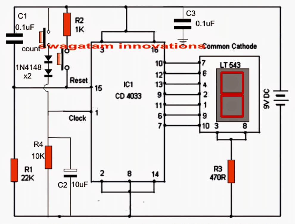
Referring to the shown simple counter circuit diagram, the IC 4033 which is a Johnson's counter/divider display decoder driver IC is configured solely for the required counting actions.
Circuit Operation
The circuit is pretty straightforward, the various pinouts used in the configuration may be understood with the following points:
Pin#1 is the clock input which is connected to a push switch via a couple of diodes and is also terminated to ground through R4 and C2.
Here the push-switch is used for pulsing the input of the IC for getting the corresponding count over the connected common cathode display across its output pins: 7,6,11,9,13,12,10.
The two diodes make sure that the IC responds only to legit switching and not to accidental spurious triggers.
R4 and C2 prevent debouncing effect that could occur during the clocking operations.
With every push of this switch, the output advances by one digit until it reaches 9 after which the display returns back to zero in order to repeat the cycle.
Another push switch can be seen connected at pin#15 of the IC 4033, this is used for resetting the IC output reading to zero at any desired instant in the course of the counting process.
C1 ensures that the IC always displays a 0 over the connected display during power switch ON.
R1 ensures the required logic zero to pin#15 of the IC for making it functional.
C3 is the decoupling capacitor, imperative for all logic ICs as per the standard rules.

Using IC 4033 IC Modules
The simplest and the best method is to use many such modules as explained above and arrange them in line for acquiring the required number of displays on the scoreboard.
Suppose we need a 4 digit scoreboard for the application, then 4 of these modules may be fixed one beside the other for implementing the scoreboard display system.
Now by simply pressing the relevant push buttons one could allow the desired number to appear in the relevant slot of the multi-digit display board.
Using the above method provides the facility of setting/resetting of any particular digit as per individual wish or requirements. This is simply done either by using the clock push button, the reset button or perhaps both during the counting operations.
Thus the above suggested electronic scoreboard becomes very easy to handle even by novices in the filed, or by any layman.


With over 50,000 comments answered so far, this is the only electronics website dedicated to solving all your circuit-related problems. If you’re stuck on a circuit, please leave your question in the comment box, and I will try to solve it ASAP!