In this article we study a simple flyback based converter design which is implemented as an SMPS 12V, 5amp battery charger power supply, without using a iron core transformer.
How it Works
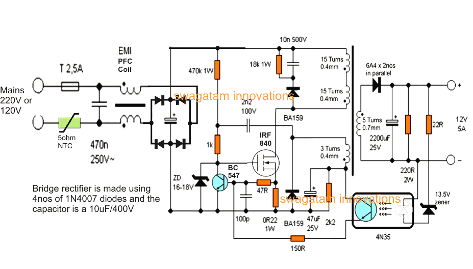
The proposed 12V, 5 amp smps battery charger circuit employs a flyback converter topology which results in the required smps based high current, compact, mains isolated converter design.
Here, the a high power mosfet becomes the main switching component and is used for triggering the ferrite primary winding with the set high frequency mains rectified Dc.
When switched ON, the 470k resistor charges the mosfet gate into conduction and initiates the switching action.
The above action induces a voltage across the auxiliary winding of the transformer which results in a feedback voltage to the mosfet gate via the 2n2/100V capacitor forcing the mosfet to conduct even harder.
As soon as this happens, the primary winding gets connected with the full 310V DC rectified voltage via the mosfet drain/source terminals.
During this process, the voltage across the 0.22 ohm resistor situated at the mosfet source tends to cross the 0.6V level, which instantly triggers the transistor BC546, which shorts the gate of the mosfet to ground, rendering it completely switched OFF.
This also ensures cutting-of the auxillary feedback voltage, restoring the entire primary section to its original switched OFF state.
The cycle now begins afresh and is switched continuously at around 60kHz rate which may be varied by increasing or decreasing the values of the 2n2 feed back capacitor and the 100pF base capacitor of BC546 NPN (it's not recommended though).
During the switched OFF periods of the primary winding, an induced equivalent back emf is transferred to the secondary winding which translates it into the specified stepped down low voltage, high current secondary output.
The above secondary output is appropriately rectified and filtered by the high current diode and a filter capacitor.
A feedback stage across the secondary and the primary stages is implemented via a optocoupler which determines the required fixed, regulated output voltage.
The zener associated with the optocoupler may be tweaked for getting different stabilized outputs for the desired applications.
Here it has been fixed to about 14.4V which becomes the optimal level for charging a 12V lead acid battery.
The current output of this transformerless 12V, 5 amp smps battery charger can also be changed by two methods.
Either by modifying the secondary wire thickness of the transformer or by tweaking the value of the 0.22 ohm resistor positioned across the source/ground terminals of the mosfet.
The input stage typically consists of a bridge rectifier stage, followed by an NTC and filter stage.
The input EMI coil is optional.
Recommended for you: 24watt, 12V, 2 amp SMPS using a single IC Must Read.
Circuit Diagram
How to Wind the ferrite transformer
The ferrite transformer is wound over a 15mm EE ferrite core compatible plastic bobbin.
The one half primary is wound first, using a 0.4mm super enamelled copper wire (15 turns).
Secure the end of this on one of the primary side pins of the bobbin. Cover the winding with a layer of insulation tape.
Next wind the secondary winding (5 turns) using 0.6mm wire over it.
Terminate the ends on the secondary pins of the bobbin.
Apply insulation tape over this winding.
On this wind 3 turns of 0.4mm auxiliary winding, cover it with insulation tape.
Finally continue from the secured end of the first primary winding and wind 15 more turns over the above auxiliary wind to finish of the ferrite transformer coils.
Put a few layers of insulation tape to finalize the winding insulation.
Fix the EE cores and tape it yet again along its periphery.
Make sure the EE core edges are separated with an air gap through a piece of insulation tape or a paper, this will prevent core saturation and stalling of the desired smps induction.
THE CIRCUIT EXPLAINED ABOVE IS NOT ISOLATED FROM MAINS, AND THEREFORE IS EXTREMELY DANGEROUS TO TOUCH WHILE EXPERIMENTING IN POWERED CONDITION, AND ALSO THE DESIGN IS RECOMMENDED SPECIFICALLY FOR USERS HAVING ADVANCED KNOWLEDGE IN THE FIELD, NOT FOR THE NEWBIES..
hello sir, sorry for again. sir
1.
I have a faulty cct of a bty belt. it’s ratting are: I/P =220vAC O/P =14vdc, 10 A. can I use this cct’s o/p transformer in this project?
2. If not then if I use this transformer in this project so what can I change/replace in this cct to make compatible with these o/p ratings (14vdc, 10 A). plz need ur guide.
Hello M.Ahsan,
The transformer must be a ferrite core type and the size and the number of turns must be exactly as per the above given specifications, otherwise it cannot be used.
thank you sir.
can I charge 3 series li-ion btys total (11.1v), wd this cct?
3 series cells will require 12.6V, so you may have to adjust the transformer turns to get this output, and also the max current will need to be limited to 50% of the battery Ah rating..
thank u sir , for 12.6 v what are the transformer specifications?
For 12.6V, you can adjust the 13.5V zener diode until the exact 12.6 or 12.4V is achieved.
Hello sir, Can I buy a readymade ferrite transformer with these specifications from market?
Hello M.Ahsan, If you can get the exact specifications then you can buy it readymade.
Can you explain what the function of the 18k resistor and capacitor coupled with it is, and what the effect is if I change the value of the resistor and capacitor?
The capacitor, resistor and the diode together form a high voltage transient suppressor for protecting the MOSFET.
A slight change in the value will have no impact on the overall working of the circuit.
hi swagatam
thank u so much it was good circuit
to build a switching power suply without i.c
best wishes for u
yasin
Thank you Yasin, glad you found the circuit helpful.
Hello sir,
I would like to have your help to design a Charger circuit for LiFePO4 batter of 12V and 5Ah capacity
need to design from the base circuit
Thank you
Hello Pranav, you can try the LAST circuit from the following article. You must replace the battery with your 12V battery, and the relay with a 12V relay, and make sure that charging input is from a constant current source such as from a LM338 current controller:
https://www.homemade-circuits.com/usb-automatic-li-ion-battery-charger/
Thank you sir
Thanks sir
Because 4N35 has 6 pins and circuit shows 4 points of connection so I am not able to connect.
Please compare the datasheet images of the two opto-couplers to confirm and match their pinouts.
Sir can we use optocupler 817 in place of 4N35.
Yes that will also work…
Inductance or air gap
paper gap is recommended between the E core legs…
Sir kindly suggest paper specification to use right paper, I discussed with transformer manufacturer but he requires inductance or paper gap.
You can insert a layer of insulation tape between the E cores.
Hi Sir for 12v 5a SMPS pls suggest the inductance of primary/ secondary coil.
Hi Mayank, sorry inductance details are not available for this circuit, only the winding details are available.
Thank you sir ,15mm EE ferrite core compatible plastic bobbin means
Transformer type and size please let me sir.
Hello K senthil, It is the plastic bobbin which fits between the central limbs of E-core. E core size code is EE15.
Here’s an example:
" rel="ugc">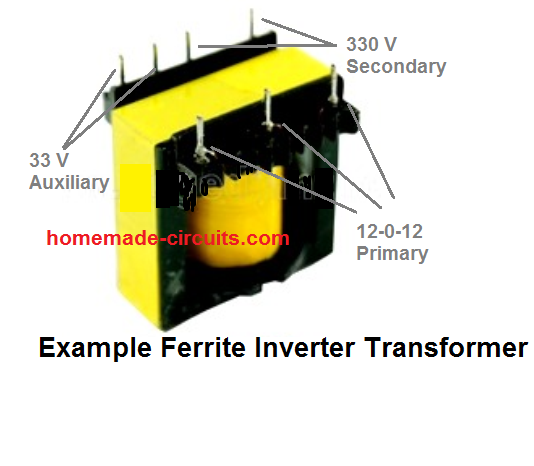
hello sir I want to know that can I use a ATX SMPS transformer core instead of ee15 can it requires more or less turn if increase or decrease of turns please tell me that turns number please reply
I will be thankful for you help and waiting for your reply teacher ????
Hi Biprendu,
The transformer is the crucial part of the circuit, and it should be built exactly as indicated in the article. So I am not sure whether the ATX transformer can be replaced with the EE15 core transformer or not. Since I do not know the inductance values of the transformer, I cannot suggest the adjusted winding details. However, you can experiment with it and see if it works or not. You can connect a 100 watt bulb in series with the input supply while testing, so that your circuit does not burn in case of a malfunction. If the bulbs glows brightly without any load, then your circuit has problems and will need to corrected accordingly.
i have not any ee15 core can you give me some link to buy this transformer or where I can get the ee15 transformer please help me
You can search the phrase “Buy ferrite E Cores” then while ordering specify them about EE15 size. However, the best place to buy them is from any local electronic spare part retailer shop
can you send me ee15 transformer core image and datasheet
You can see the following image:
" rel="ugc">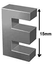
i found the transformer from a cfl circuit i match the size and it’s 15mm
That’s great, remember to put a paper gap between the E cores. Meaning when you close the two cores inside the bobbin make sure the E core edges do not touch each other directly, instead put a piece of paper of insulation tape between the edges that meet each other.
ok sir ☺️ thank you for helping me really appreciate to you sir ????
No problem Biprendu, all the best to you.
i found this transformer from cfl and it’s core size was 15 mm
https://drive.google.com/file/d/1pjI0bO1vkRqS2ftb1Izl8xe7TPQO38bT/view?usp=drivesdk
Make the link “sharing” otherwise I cannot access it.
i found this transformer from cfl and it’s core size was 15 mm
https://ibb.co/ctBCPwQ
The transformer in the image should work. Make sure winding fits inside this core properly.
can I use ee13 transformer core please tell me ???? please wire turns for ee13 transformer
EE13 will not accommodate the winding.
Sir, Do you have any SMPS circuit based on DK1203 ?
Hi Sanjay,
Did you refer to the following datasheet, it has all the required details you want:
https://grupoautcomp.com.br/wp-content/uploads/2016/11/Specification-IC-DK1203.pdf
Dear Swagatam,
this datasheet shows ee25 ferrite core, but it is used for a 110v AC input SMPS (Hence Vs =85*1.3=110V) If my input is 220v AC, can I use ee25 ferrite core for assembling this transformer? Is the calculation on this datasheet will be the same for 220v ac input?
Thank ypu for your help
Hi Kamussuwanto,
A ferrite core size should be such that it accommodates the winding comfortably, neither cramming it nor leaving too much free space. So if your EE25 frrite core is not too large leaving too much internal space, then it can be used for the above SMPS.
Dear Swagatam, thank you very much for your quick reply
You are welcome Kamussuwanto!
Sir, Can we modify the above circuit to get output of 80V-10A ?
Which components needs to be added/replaced for the same?
Thank you very much in advance.
Hello Imsa,
For this upgrade you may have to modify the number turns on the transformer. You may also have to reduce the value of the 0R22 resistor at the source of the mosfet. All these will need to be experimented cautiously.
Can you make this 12v 5a smps for me
If I made it, can it use for supply the 22inches led tv ( changhong 22c2600 ) ? Its smps has damaged and the output write on the pcb board is only 12v out for suppying the tv entire system.
Thankyou n I hope you answer me.
If the LED TV is a 12V unit then you can use the SMPS to power it. However I would recommend buying a ready-made unit instead of building one.
I want -14v 0 +14v 5amp ckt diagram and pcb layout
Plz provide me
You can try 12 turns at the secondary of the above design with a center tap and see if that produces the required dual supplies?
Sir please your phone number
hi good teacher. I’d like to ask? what makes 470k and 18k resistors heat up fast? from the first try i have worked perfectly from this schematic but when i made the second one by trying to convert it to higher amperage i have problem 470k and 18k resistor getting hot, other than that everything is perfect only problem is when i make trimpot to get 30v, the resistor starts to smoke, I also change the 10uf capacitor to 100uf, but if I change it the low voltage is 14.4. safe resistor, why is that? I made primary winding 25+25 auxiliary winding 4 secondary winding 5 +5 ct, I combined this schematic with https://www.homemade-circuits.com/how-to-make-variable-current-smps/ to get the correct voltage true can be customized
Hello Zen, It can be difficult to find the exact reason, but you can rectify the fault in the following manner.
Instead of using a single 470K resistor, use two 240K resistors in series. Similarly instead of using a single 18K, try using two 10K resistors in series. Please do not change the 10uF to 100uF, use 10uF only as indicated in the diagram.
okay, thank you my best teacher, for the advice you gave, I have solved this problem by changing the value of the 470k resistor to 680k and 18k to 63k, and the coil that was 5 + 5 secondary, I made it in series without CT, what do you think about the changes do i do that? , now I can turn the trimpot to 35volt safely without heating the resistor, but I haven’t tested it with a load, later if I have tested it with a load, I will tell you my best teacher, greetings and thank you for the guidance
OK, that sounds great. According to me two resistors in series would have worked better, as suggested by me in the previous comment.
okay, I’ll try, the teacher’s advice, from the formula like my previous comment, I have tested it, and the results are not very satisfactory, at a load of 3 amperes, the voltage drops from 35 volts to 13 volts, unlike my first assembly, my assembly the first one, even though the load is up to 5-6 amperes, the stable voltage is still 35 volts, ok sir, I will apply the teacher’s advice by changing the 630k resistor to 470k in series as you suggested, I’ll let you know the results of the load test later
Sure, no problem, you can try it.
Dear Sir,
 " alt="12V 16V 5V SMPS circuit" />
I like to have a power source of 16V 12V & 5V @ 1Amp to use in circuits such as the 0-100V Adjustable SMPS Circuit in your blog and also in other circuits which can power cooling Fan OpAmps etc. I am unable to built, nor find one.
I tried to make this circuit
copied from your above and Make this 3.3V, 5V, 9V SMPS circuit without actually understanding the working of the circuit! I am at a loss as how to provide feedback to the 5V,12V & 16V Outputs (or will the circuit work?). Could you please advice necessary corrections? Alternately please suggest a suitable circuit.
Thanks in anticipation.
Hi Imsa, In the above circuit, the feedback is already provided to the 16V output using the opto coupler and via VR2. When 16V is controlled, then the 12V and the 5V will be also automatically controlled.
Thanks a lot for your express reply as always !
Does it mean that the circuit given above is expected to work without any changes ?
Thank you very much indeed for your time and advice.
I am glad to help Imsa. If the SMPS is from a reliable source and is a tested design then yes it can be used without any changes.
hi dear teacher. I continued this circuit and I modified the output section using a MUR1560G diode to produce a 17volt voltage with a 25volt 4700uf filter capacitor and a VARIABLE REGULATOR LM317 WITH DARLINGTON MODE AMPLIFIER using tip41 and tip3055. I used 1.5mm 4x copper wire. my question is why does the MUR1560G diode heat up fast? and the regulator heats up quickly even though the load is only 2.5 amperes. that’s the first thing I said. second, when I replaced the LM7812 with a fixed regulator with a 12 volt dc fan load only, the regulator only lasted a moment and immediately broke down and immediately took care of the main mosfet in the primary. Why that can happen, your answer is very valuable to me. greetings from me my best teacher
Hi Zen, as you will understand for any SMPS the transformer is the main element which needs to be wound very accurately, even a slightest bit of discrepancy in the winding can lead to the burning of the devices. By the way did you put a paper gap between the edges of the e-cores which touch other? Make sure you do it otherwise the core will saturate and burn.
At 2.5 amps the MUR1560 can never burn because it is rated to handle 15 amps. I guess the MUR1560 might not be original and therefore it burned at 2.5 amps. I think you should confirm with an ammeter if the output current is really 2.5 amps or more.
So basically you have to add a paper gap between the ecore edges which meet each other.
And also you can add a few more turns on the primary side winding and check if that helps to make the design more stable.
Yes yes..sorry..Master..Accuracy in electronics. It turned out to be very, very important. And the calculated value must be accurate. Sorry sorry teacher sorry for my analysis error. This is not a winding problem or paper defect in the transformer. Everything is correct. But I didn’t really imitate the circuit the teacher presented. I prefer to modify with my knowledge. My problem this time is that I am not careful in choosing components, the MOSFET I bought is IBGT, it turns out that the 20N60 MOSFET has two different letter codes, it could be that the component I bought is wrong. Ah aha.. Now I can solve this problem by replacing the MOSFET with a 9n60 type. And I installed the LM317 variable regulator and its voltage amplifier. And I also included a 7812 fixed regulator for the fan. And everything works fine without overheating at a load of 5-6 amperes and the voltage is stable. I measured all of that with an avometer and a voltmeter. Because at home I have a lot of tools and electronic components. Thank you for your attention, the best teacher. oh..yes someone forgot. I replaced the MUR1560 diode with an HBR2045 diode because the MUR1560 diode has too high an rms for what I need and that could be a problem because I only need 17volt and 32 volts because I wrapped two secondarys inside the transformer
That’s great Zen, I am glad you could solve the problem so effectively. Thanks very very much for your honest feedback. Have a great time with the project.
yes..yes..I am very happy to be able to make the circuit that you present can run well. and this is a very satisfying result for me. even with my heart pounding while testing this circuit. because I have to deal directly with 220 volts AC voltage that can sting me.
This is my first time making a circuit that is directly related to AC voltage, this can replace my iron transformer power supply, for the transformer battery charger I made this is more effective than my iron transformer, this SMPS makes the battery charger full faster than I use iron transformer. However, the weakness of this SMPS is that it does not last long when a short circuit occurs, unlike iron transformers which last a long time when a short circuit occurs, according to my observations. But I am very happy to be able to make it, thank you for the guidance of the best teacher, I will develop this circuit again, because I see SMPS like this, the output section is equipped with many ICs such as the Tl494 IC, there are also those that use LM339N, sometimes the pins are quite a lot. like SD6109, I still don’t understand what the function of the IC in the SMPS output is, its type is like this
Thanks Zen, yes an iron core transformer based power supply will be always more reliable than an SMPS. The main advantage of SMPS is that they are small, compact and lightweight. The above circuit is a very basic design without any ICs…..but the other SMPS designs that you are mentioning are more sophisticated and have more protection stages using voltage regulators and comparators like LM338 etc.
Oh I see.. Yes, does the teacher have a circuit
more protection stage using a voltage regulator and comparator like LM338 On this blog?
Oh yes I observed when I made two secondarys, indeed the voltage would increase if the first secondary installed in the opto was loaded, when I made only one regulator,
Maybe I can work around this by using the same regulator on both secondary. That’s according to my assumption, hehehe… true or not I don’t know yet, I’ll do it soon. But for now I’m only using one regulator, and I’m not using the second secondary, I’ve tested this for a battery charger for about 12 hours with a 0-6 ampere load, the circuit is safe, and it doesn’t overheat, its a bit just a HBR2045 diode that heats up, but I think it’s natural considering the HBR2045 diode is a SCHOTTKY BARRIER diode that has hot properties. Is my observation correct? Good teacher… greetings from me
Actually the protection must be applied through a feedback link which the above circuit has using an opto coupler but using an opamp is also possible. I do not have the design using op amp. If I find one I will surely update it here. Yes you can try using the same regulator for the your two secondaries, hope it works.
I am very happy you could make this simple design so useful, which is now working like battery charger for you. All diodes will usually heat up even if only 50% current flows through them, but I am not sure if a schotky diode can heat up faster or not? I appreciate your efforts!
Thank you very much, for the guidance, the kind teacher. I will also complete this circuit with an auto cut off based on ne555 which is also available on your blog, later I will tell you the results, thank you for your attention answering all my questions about electronics
You are most welcome Zen, all the best to you!
Please I will be glad sir if you can help me out sir I’m 200 level electrical/electronics engineering and I also learn electronics reparing for 5 years before I gain admission in to polytechnic please I’m begging you sir
Thanks for your quick response sir, please can you help me to create +/-14v 80w flyback smps circuit sir to power my tda2030A amplifier, because have try a lot in constructing this many time using Uc3842 but once it gives output and connect it to my amplifier it will on but if I increase the volume to about 45% to 60% it used to kill the power Mosfet and in totally tired of this sir please if you can enlight me on this I will be very grateful sir because i don’t want any other type of smps I want to successful on flyback smps
Azeez, designing a perfect SMPS is a difficult job, and I do not have full expertise in this field so far. I would recommend you to go for a transformer based power supply instead.
Hello Sir, if i want make a 220V to 20V(400W) SMPS, which component should i change?? thanks sir.
Hello Fernandy, you can try modifying the following concept which looks close to your required specifications. You can reduce the secondary number of turns to get 20 V.
https://www.homemade-circuits.com/smps-2-x-50v-350w-circuit-for-audio/
Good evening Sir,
Sir I am having EE25 core, may I use this core . Also I have 20N60CFD , IRF740 . Is it possible to replace IRF740. Sir please guide me.
Hello Swagatam
I really appreciate your work your are really doing a great job kindly keep it up ????
I want to ask you that can I use 0.10mm or any other diameter of wires due to unavailability of wire type used in your circuit ??
If your answer is yes then can you please tell me if I change the wire diameter will I have to change no of turns in primary and auxiliary or not ??
I wants to make 12V 2.5 Amp SMPS Circuit. I tried it using making through 13005 transistors but maximum time transistor burns or didn’t worked properly for me.
Thankyou
Thank you Saurabh,
If thinner wire is used then the E core bobbin should be also selected proportionately smaller, otherwise it may affect the performance, according to me. The rule of thumb is that the winding should accommodate inside the transformer space optimally, there should not be too much space left and also it should not be too much crammed.
If the e core bobbin is correctly selected then the number of turns can remain unchanged.
However I would recommend to follow the schematic details exactly as given, any changes might trigger a fault.
Thanks for the response sir , i need to design a smps based charger which is not bulky for that what should i do , use an smps available or you have any design , if you have any ready circuit which can be used for commercial use pls let me know i am ready to pay for the design , thanks a lot ,regards
You are welcome Sunil, sorry I do not have a 48 V SMPS circuit with me at this moment, I would recommend buying a readymade unit and then use it with the cut off circuit.
hello sir , you have great knowledge searched ur site recently
i need 48 volt 6 amp charger circuit for lithium ion battery
if you have the pcb design ready or product ready pls let me know , or have circuit which can be used for practical purpose pls let me know my email id is ydv.sunilsingh@gmail.com or can tell me on 9999914788
regards sunil
Hello Sunil, you can try the following auto cut-off with current control design:
Initially adjust the 10k preset to ground level, then feed a 56V Dc from the Battery side (left side).
You will find the LED switched ON.
Now slowly adjust the preset so that the LED just shuts off….
this will set the circuit for cutting of the battery at 56V when the the actual charging is done, by feeding the 56V DC from the right side and battery connected on the left side.
hello ,the author of post. I’m student of university and my major not electronics engineering, so i can’t understand all the post.I have question and i thankful if you answer my question. My question :
– your circuit is blocking oscillator using negative feedback so i understand the operation of this but i don’t know principle of diode BA159.What is mission of it in circuit ?
Hello, they are probably for neutralizing the reverse emf transients from the transformer primary.
how can man make a space of 1 mm in the ferrite core?
which elements in this project are responsible for switching frequency of 66 khz?
Have a question. I have a standard computer power supply from an old computer that I would like to turn into a battery charger. The supply is a 380w unit capable of powering newer hard drives (3.3v).
I would like to use it for at least li-ion and/or lipo cells if possible without internal mods. External circuits are ok. Thanks much for the help.
You can use the SMPS for charging a Li-Ion battery, but a 3.3V will need to boosted to a higher level, maybe 5 to 6V for charging a 3.7V Li-ion.
You may need a boost converter circuit for this, such as this one:
" rel="ugc">
Hi Swagatam,
You doing a great job
I need a transformerless power supply 5V and 3.2V total current 300mA~350mA, Can you send me the circuit for my project
I am going to use this circuit for my product
Thank you bala, you can modify the following concept according to your needs
https://www.homemade-circuits.com/simple-220v-smps-buck-converter-circuit/
Do you have current limiting options here? If more current flows during battery charge, will this circuit not burn out? And what kind of core have you used here? Thanks.
Current limiting is already included through the 0R22/1 W resistor. Core is ferrite core
Hello sir, we highly appreciate your work.
Is the above circuit implemented in real?
Thank you Shrijit, yes it has been tested by a few visitors, but not by me. That said, the design is quite crude and the parameters are not perfectly calculated, so you may have to experiment a bit until proper working is achieved.
Dear sir, please I want to build 12V, 10A SMPS but my problem is the ferrite core transformer since it’s not available in the market. Please sir can 15V, 2A step down transformer used with amplifying components output 12V, 10A?
In other words, please sir I need a circuit that uses a step down transformer for the 12V, 10A circuit design, instead of transformerless mains supply to the circuit which in turn will need ferrite core transformer for the required output.
Thank you very much sir
Godfrey, 12 x 10 = 120 watts, whereas 15 x 2 = 30 watts, so it cannot be used to produce 12V 10 amp.
Okay sir, thank you!
So that is to say the 2A transformer can’t be amplified to produce 5A.
Dear Swagatam,
We are not finding the 5D11 NTC. Can we replace this with 10D11 NTC?
best regards
Prakash Srivastava
Dear Prakash, 10 means 10 Ohm resistance during normal operations from the NTC, I assume this much resistance will be OK for your SMPS, in that case you can use it.
Dear Swagatam,
I need one small help. I am looking for transformerless 12 V 10 amp or 12 V 15 amp DC circuit, which can provide fix voltage for my circuit.
Your fast reply is highly appreciated.
Thankyou in advance !
best regards
Prakash Srivastava
Dear Prakash, sorry I do not have a 10 amp rated SMPS circuit with me, I guess it is better to buy one readymade, since it could be quite a complex design to build one….
Dear Swagatam,
Thanks for your quick reply.
Yes, you are right, we can purchase a readymade one. But our problem is, we are making a product and we wanted to have all our circuit all together on one PCB. That’s why we are looking for a 12 Volt 10 amp transformerless SMPS circuit.
If we use transformer, the size of 10 amp stepdown transformer is too big for our PCB and heavy too.
Our existing circuit needs 12V 10 amp DC. That’s why we want to change 220 V AC to 12V 10 amp DC. We are looking for sm lightweight transformerless power supply solution.
Check, if you can help!
BR
Prakash
Thank you Prakash, If I find a suitable design I will surely let you know!
Hi! Please give me exact sizes of EE transformer.
Hello sir
I have a question, does this circuit have short circuit protection?
If there is a short circuit, can the power supply be damaged or burned?
Is there a way to add a short circuit protection?
I will use the power supply to power a 3d printer and I am concerned about damaging the electronics in the event of a short circuit.
Greetings from Mexico.
Hello Ramon, yes it has a short circuit protection due to the current limiter stage formed by BC547 transistor and the 0.22 Ohm 1W resistor
Hello Sir,
Most of EEcores and bobbins i have recovered from ATX PS have approx. 0.2mm gap in thier centeral legs.
Is it enough or should be more or less?
I know that i have asked this before, sorry, i am trying to find the problem in my circuit and you are the only reference i have.
Thanks
Hello Mah, as per my knowledge, the gap must be adjusted by inserting a paper between the E-core contact edges. Just add a piece of paper and then tightly wrap the E-cores with insulation tape and epoxy glue….put the glue only once the results are confirmed
In the transformer i wound for my circuit, the middle leg of core has a 1mm gap when its side legs fit together, may i have problem with it?
Generally, Can we choose the core which fitted with the desire wind wires? I mean have enough space to takes all the winding we need?
Thanks
According to me the gap must be separated with a paper sandwiched between the core touching edges. If there’s lot of space left in the core, that will not work, the core and the bobbin must be well matched with the winding volume.
Hello Sir,
Can i use 100pf/1kv and 10nf/1kv for those capacitors in the circuit? If not, what are the suitable rated voltage for 100pf and 10nf?
Is it possible to use couples of them in order to reach target value?
Thanks
Hello Mah, yes it will do, because higher voltage values will not do any harm. You can use series parallel combo to reach the values.
Hello
What are those points near each coils in the circuit diagram? What information they are telling? I saw them in most smps transformer circuits.
Thanks
Hi, those are start points of the particular winding, because winding also have polarity.
What modifications should be done to this circuit to be used with 400V DC.
Required Charging Lead acid battery 24V at 10A.
Isolation is not required.
Thanks.
you can try increasing the zener value to 24V, and also modify the transformer wires for handling 10 amps
Hello,
The SMPS design in this article is truly great! But I’m planning to use 12v 5Amps SMPS in a enclosed body instead of open ventilation. So my question is whether is there any possibility to avoid heatsink or any other solution which can be implemented to avoid failure caused by operating the circuit in enclosed body.
Thanks in advance.
Cheers.
Hi, thanks! Glad you liked it… However this article was contributed by another author and is not designed me, so assessing the improvements can be difficult for me, especially since it may require some critical calculations to be done. In general you can try optimizing the frequency determining parts and check if that helps in increasing the efficiency.
Hi Swagatam
You have used 1N4007 diodes at the starting which have a current capacity of 1amp but the SMPS can supply up to 5 amp so will the diodes get damaged????
Hi Shuvam, the 1 amp is related with 310 V, so it becomes 310 watts maximum, the output is related with 12 V 5 amps which becomes only 60 watts.
Dear Swagatam,
can you please design the circuit of input AC 220v and output DC 12v / 8amp. with component name.
Dear Murtaza, designing SMPS is not easy, so i won’t be able to help you in this regard.
How to calculate transformer winding turn in flyback converter? Or a good software to calculate it.
Try this
https://www.homemade-circuits.com/how-to-design-and-calculate-ferrite-core-transformers-for-inverters/
i am ilyas raza , i want to design th SMPS power supply which vary the vlotage from 50 to 100 voltage with 450 watt rating , please suggest me the circuit ,can i used this circuit with modification
Hi, you can try the following concept
https://www.homemade-circuits.com/adjustable-0-100v-50-amp-smps-circuit/
Hi i want to design 8.4v 1A Li-battery charger. can you please help me to design battery charger. thanks in advance.
Do you mean SMPS circuit?
HI friend!
-i have ferrite EE16 and EE20, which is best to use? without changing the windings.
-the capacitor 100p, which volt value is?
-IME : i have UU9.8 UF9.8/10,20,30,40,50 MH
UU10.5 UF10.5/10,20,30 MH
If can be used any of them?
greetings
Hi, The core can be E20, 100pF is 100V…not sure about the other elements.
Dear Sir ,
Kindly help out regarding your above mentioned circuit .
(1) Can I charged 12v and (200 AMP ) battery through your circuit ?
(2) If some one connect battery with wrong polarity ?
Dear M Gohar, this circuit cannot be used for charging a 200 Ah battery, you can do it by purchasing a 12V 20 amp SMPS unit and adjust the output to 14.1V and then easily charge your 200 Ah battery in 12 hours.
Can this circuit charge a 20ah-50ah battery without any modification?
yes it can!
Hello Swagatam
Could you please explain me how the circuit is non-isolated while you used transformer? the transformer is Isolated device in addition you are use photo-copler so the output in this case is totally isolated.
thanks
Hello Ehsan, the warning is for the person who is constructing the circuit. While testing it in open condition, the primary side of the circuit will be exposed and may cause a fatal shock to the constructor, if not careful.
hi sir can i make this suplly for 12v 1a. what could change in this circuit
It is possible, by reducing the thickness of the transformer wire and dimension, and by adjusting the 0.22 resistor value
Hello dear sir how I can make 24v 100A power supply .
Please contact on mail. mchana86@yahoo.com
Hi Yamin, sorry I do not have a 100 amp smps circuit at this moment.
Dear Sir,
I am using same circuit for my 6 volts 1 amp smps power supply for small audio instrument. I myself assemble the smps including the ferrite transformer winding manually since few years. Only the components values and transformer no. of turns are different.
For curiosity I assembled this project but it is not working. 100 watt incandescent lamp in series with the circuit as precaution for testing is lighting brightly and no out put voltage. I have wound the ferrite transformer correctly, as per your specification (15+15 turns primary-26 swg, 5 turns secondary-22 swg and 3 turns auxiliary-32 swg) following dot convention as I am very much used to it, on EE25 ferrite core, MBR20100CT double diode for secondary side rectification , EL817 opto-coupler and 220 ohm 2 watt resistor as dummy load. No components are getting hot or damaged but no output voltage.
In my circuit it uses EE16 core with 55+55 turns primary(36 swg), 14 turns secondary(26 swg) and 14 turns auxiliary(36 swg), FQPF4N60 MOSFET and slight change in other resistors value which works fine.
Can I check the voltages at primary side, like bias voltage, while the 100 watt bulb lighting brightly to find out the fault or will it damage the components if I run it for long in that condition.
All that I am having is DMM only. Please inform me how to troubleshoot.
With regards
Raveesh
Hi Raveesh,
a flyback smps is a critical device and needs to be designed with calculations, it is not possible to change the parameters linearly to achieve a desired output result. So I think your circuit may be having discrepancies that’s why it’s not working.
The bright 100 watt simply indicates that your circuit is not oscillating and it’s short circuiting the input supply through the mosfet.
Since I am not an expert in smps calculations I cannot correctly suggest what may be causing the inaccuracy in your design.
I have the following article in my website which shows how critical the parameters are in an SMPS circuit.
https://www.homemade-circuits.com/how-to-design-a-flyback-converter-comprehensive-tutorial/
Dear Swagatham,
I request you to publish or send me a pcb layout for 60 vdc electric bike charger. Thanks for your technical support for the electronics community.
jayarajan.K.B
Dear Jayarajan, Presently i do not have the PCB design for a 60V charger. I can suggest a circuit diagram if you wish!
Hi sir! dear sir i have design an smps with output of 5Amp & 14.5v, giving the output with no problem. but the smps chopper is making a small noise & also by connecting to 120AH-12v battery it show series light indication & also giving output. i don’t what’s the problem with the circuit how can i correct these problems?
Hi Sheraz, Which schematic did you use? Make sure the transformer winding is wound tightly without gaps and the working frequency is above 50kHz
i use a ready-made smps transformer for 10Amp-12v power supply. where in the circuit the uc3842 pwm controller was set a 54 KHz. i have use the same values of resistor and capacitor for frequencey it gives output but make a little chirping noise.
SMPS circuits are high-precision circuits, so little mismatch could make it inefficient and problematic, so it can be difficult to diagnose the fault verbally. Still you can try increasing the frequency a bit higher and see how it responds.
Sir, If I need a 24volt 5apm smps, what changes need with the schmatic? I try to make a 14.4 volt 25.2 Ah NI-Mh battery pack charger. Plz help
Ajitkumar, for charging a 14.4V battery you will need around 17V as the input, 24V is not required. You can buy a laptop charger and use it for the same with a simply auto cut off circuit in the middle. Making an SMPS can be a complex task if you are not well versed with all the procedures
Sir
I have prefered your LM338 based cut off circuit, thats why I ask for a 24 volt smps. However, I want to make this charger more than 50 ps quantity in low coast.Laptop charger will not be available in my budget. Thanks again for the valuable reply.
OK, then you can try modifying the secondary side of the above 12V 5 amp smps design to get 24V, or you can also try the the following smps design:
https://www.homemade-circuits.com/2017/07/110v-14v-5v-smps-circuit.html
ignore the 105V and 5V sections, modify the 14V winding to get 24V by changing the turn numbers and by adjusting P1. You will also need to use slightly thicker wire for N1 winding.
hello swagatam, ive two questions
1-Can i use mct2e optocoupler instead of 4n35 & also replace ba159 by fr107 ?
2-I cant find .4mm wire from store so can i use those taken from cfl transformer which is generally available ?
Hi Charan,
1) You can use MCT2E, and FR107
2).4mm is not critical you can try any nearby value
Good morning Sir!
This time ,I want to try to make this Battery charger.As I look to the diagram,
there is no value for the EMI PFC coil.Pls can you give me some hint how to difine the value and/or how to make it?
Shigida, the coil is not too critical for home use.
you can use 20 turns of 0.5mm magnet wire on each side over a ferrite torroidal ring.
i ve 3524 inverter if i apply feedback frm output secondary there is problem but without feedback no problems feedback is applied to pin1of 3524.what can i do
what kind of problem are you facing??
Sir i have 12v 1amp powersupply led driver. Can i convert it into 14v 10 amp powersupply just by replacing the transformer with thicker wire and adding more winding and replacing the transistor with more powerful one.
Thanks for the quick reply on other threads
you can do it, but make sure to do it from both the sides primary and secondary with proper calculations
Can i use bigger ferrite transformer instead of the stock one in the circuit
the ferrite core must accommodate the winding perfectly, it should not be big and loose or too crammed…
Mr. Swagatam, I am looking for a circuit that will take an input of 50v down to 12v with an output of 12v. Max current output around 5amps. The input voltage should be an automatic sense. Any help will be greatly and thankfully accepted. Thanks much, Joel
Joel, you can try any DC to DC buck converter such as this:
https://www.homemade-circuits.com/5v-pwm-solar-battery-charger-circuit/
I am not sure if I gave you all the information. what I am trying to do is be able to connect to say a forklift (24 to 48 volts) and get the 12th out I need, the issue is that I want to connect to any voltage between the 48 to 12 volt range and the circuit be able to take that and give me the 12v I need, without any manual changes from me.
You mean you want to have a constant 12V output from any voltage source between 12V and 48V? Is that right?
Did you consider using a linear voltage regulators, and what’ll be the required current output from the 12V?
correct on the output voltage, the current output needs to be 5 amps. I have thought about linear regs but, most have a 40 v max input.
You can try the following concept, ignore the current control section if you don’t wish to use it.
https://www.homemade-circuits.com/universal-variable-power-supply-circuit/
Sir
I need a 38 volt 9 amp Lead Acid automatic battery charger circuit for Three 12 volt battery charging in series.
Do you have any suitable circuit diagram ? Please help.
regards
Ajitkumar
Ajit, you can try the circuits presented in the following article:
https://www.homemade-circuits.com/make-this-48v-automatic-battery-charger/
Hello Mr Swagatam, I have built the power supply as you have detailed. It will work at low (30V) but self destructs at mains (240Vac). Has the circuit been designed for 110V or 240V?
I have found similar circuits, but they use a far larger number of turns on the primary winding. I am also concerned that the 0R22 resistor is too low a value to initiate oscillation.
Any advice you can provide would be most useful.
Regards Stewart.
Hello Stewart, This design is for 220V operation and is thoroughly and successfully tested by many of the blog readers.
Hello dear sir,
i need help sir can you explain this cct diagram with the help of block diagram on this schematic like driver section, oscillator section etc….
Best Regards:
Farooq
Hello Farooq, the stages can be easily visualized by looking at the diagram, there is bridge rectifier stage, after that there is a mosfet stage which acts like a driver stage as well as an oscillator stage. The BC547 stage forms the current control stage while the opto coupler forms the feedback control stage for stabilizing the output
Hai sir ,
I need 60v/3amps charger circuit for battery charging . and it should be cv and cc .pls suggest me the circuit .
Hi Pavan, you can try the following design
https://www.homemade-circuits.com/how-to-make-versatile-variable-voltage/
Thanks for your replay .sir actually i want to design 60v /3amps charger circuit in flyback topology . i need perfect design . pls help me
Pavan, you can try and modify the following concept
https://www.homemade-circuits.com/smps-2-x-50v-350w-circuit-for-audio/
Dear sir! i am using pesim software for designing smps transformer but i dont understand about the wire guage let say AWG25.5 x 3, understand AWG25.5 but for what the x 3?
x 3 could mean 3 wires held together and wound together in a bifilar mode. 3 wire strands wind up simultaneously instead of one single thicker wire, this helps in getting better skin depth, higher amp efficiency, and compact winding
TRANSFORMER SPECIFICATION FOR 12V 5Amp OUTPUT AND PLEASE HELP ME WITH SOME EXPLANATION ABOUT THE TRANSFORMER
the winding procedure is already explained in the article
is it tested for 12Volt 5Amps o/p
yes it is fully tested!
CAN I USE THIS CIRCUIT AS 12V 5AMP SMPS POWER SUPPLY
yes you can, for more options you can check out this link
https://www.homemade-circuits.com/?s=smps
sir please send me the transformer coil inductance
inductance is not there with me, but the winding details is given in the article and should be enough for the construction.
sir,
please publish pinout of 4N35 optocoupler to the board,there is no indication please update on circuit immediately.
you can check it from the datasheet of the IC, or from Google images, it’s just a matter of a minute.
Ok sir but the anode and cathode of optocoupler connect to which part of the circuit please explain….
anode can be seen connected to zener diode, and cathode to (-) line
Thank u sir for your immediate response..bcz of white background cant notice.
you are welcome!!
Hi sir, i made this circuit but it’s didn’t work
The output voltage is 0v
I used 1n4007(standard recovery rectifier) instead of ba159
And 817 optocoupler
I replace 10uf 400v with 100uf 400v
And i remove NTC and EMI
Can you help me to solve this problem?
Thanks
Hi Zakie, It can be difficult to troubleshoot the fault because I cannot check what may be the problem in your circuit…the ferrite transformer is the crucial thing in the design, if it is not wound correctly then the circuit will simply not respond or even burn into flames…so check the transformer once again and also the other connections. the circuit should first oscillate to produce any form of result, so check whether your primary side is oscillating at a frequency higher than 20kHz or 40kHz
But can i replace ba159 with 1n4007(standard recovery)?
and what is mean of dot(.) in your schematic sir?
for testing purpose you can do it, but for the final use it must be replaced with a fast recovery diode…
And can i use 0.25mm wire for all winding?
Thanks sir
for experimenting you can try it…it should work with some unknown current output.
always connect a 100 watt bulb in series with the input AC supply, in case if something goes wrong….
Dear sir ,
please describe the Ferrite transformer turns calculation with example and auxiliary winding.
Armaan, the details are already given in the article, you have to do exactly as per the given specifications
thanks for your quick reply i was a little worried have a gud day sir
you are welcome Olupot!
hello sir i have a question can i use a 4pin optocoupler when i do not have a 6pin optocoupler with me thanks
Hi Olupot, yes you can use it….no problem
if i use bigger VA core can increase power?
yes, I think that's possible, the 0.22 ohm will also need to be modified
hello sir nice day and thanks for the great job you do i appreciate. now sir i needed a simple personal multi output charger but using the same circuit. i want it at 5v 2amp,9v 2amps, 12v 5amps, 20v 3amps wat can i modify to get all those out puts thanks alot
Thanks Olupot,
You can try modifying the opto resistor and the secondary winding to get those outputs, or simply you can modify the optocoupler section with a pot to make the output variable, as I have explained below:
https://www.homemade-circuits.com/2015/04/how-to-make-variable-smps-driver-circuit.html
Sir hi again.We have discussed on comment section of your other smps homemade circuits. I want to ask you some questions to define some issues.
First you mentione a 15mm EE compatible bobbin on the end. Is this an EE15 core? Cause i think that with a frequency of 60kHz the minimum ferrite core that can provide 60watt (assuming flyback topology-PC40 ferrite material-minimum air gap possible) is EE25.
I will test your circuit using EE25 (salvaged from a HP inkjet supply) on 60 and 120 khz and keep you posted about the results.
Nice simple and very educational self oscillating flyback operation explanation. If you try understand the same oscillating operation from the variou pdfs around the internet…good luck! Thank you!
Thank you S3nsit,
the rule of the thumb is to use a ferrite core/bobbin that accommodates the specified winding data with minimum gaps, that is in the most optimal way, making sure that the winding is done using a winding machine not by hand.
here we cannot use formulas or calculations for the transformer because the design has been thoroughly tested, and if everything is done exactly as per the given data the circuit has to work without fail… and moreover the winding details are not extremely critical, a little discrepancy will not cause any harm to the final output…
Ok in understand. By the way i think that most people complaining about mosfet overheating they used their EE cores as they came from factory. Ungapped. Zero gap as you mentione causes saturation, fall of inductance so the transformer primary coil becomes a short circuit thats why mosfets overheats.
If people are reading this in order to add air gap, take on of the two EE halves and trim its center leg with no600 sand paper. Taking care not to damage the outer legs of EE half.
OK thanks for the updating the info, however I think inserting a paper between the outer arms of the E cores can be an easier option….
Hi Sir. I want to salvage some components from an old ATX PC power supply so could this design be adapted to use a transformer with 20 + 20 turns primary winding?
Hi Gustava, No, the above smps circuit cannot be used with any other transformer except the one which has been specified in the article…
Sir, i want to build a smps of television set using already existing transformer but i want to use uc3842n and 8n60 and i don't want to use optocoupler, please help me. I want variable volts of 110v – 135v. Please help me. I can't easily want transistor driver instead of ic but with no opto.
OLybest, It may be possible only after doing proper calculations and modifications, you cannot simply connect a available transformer with another SMPS circuit, that can cause malfunctioninh or even a fire…an example article can be seen here, please check out how all the calculations are implemented for achieving a precise and safe functioning of the circuit
https://www.homemade-circuits.com/2017/06/12v-2-amp-smps-circuit.html
Dear Sir
Can you send me 12 volt 5 amp power supply i am in mumbai My address is PROX SYNERGY , b16,bharat market,subhash nagar,asalpha, ghatkopar west
mumbai, 400084 and please tel me how to pay what is amount
Dear Rajan, if you are located in Ghatkopar then visiting Lamington road shouldn't be difficult for you?…you can go to Lamington road and get the desired SMPS of your choice from there at the most reasonable cost…
Hi Swagatam Majumdar,
Very good DIY instructions, What will it cost in INR? I am very lazy at the moment, can you quote for 9V 5 Amp with casing and deliver to Rourkela, Odisha? Vijay
Thank you Dubba, the final cost including shipping will be around 600/-INR…the actual cost could be anywhere near 300/- INR
Do you mean both 12V5A psu and 9V5A costs the same? But you didn't mention that you can ship one 9V5A converter to my address, via courier? I am actually in need of one of 9v5A and 12v5A each ASAP & and can't afford to divert attn. (lazy) in scrounge parts for DIY of above.
12V will be costlier….however sorry I may not be able to send it due to my busy schedule, initially I thought that I should start selling items in my site but for the moment I have decided not to go ahead with it due to lack of time…
Hello
Thanks for posting nice SMPS circuit!
I have a small query
0.4mm is used for primary and auxiliary winding
and 0.7mm copper is used for secondary winding
is there will be any problem if we will use all windings with 0.7mm?
No problem, you can use 0.7mm for all winding
Sir,
could you please tell me what exactly is the function of EMI PFC coil.
If my input is 230V,30A what value of PFC coil should i use?
Ajay, PFC coil cancels the reverse EMFs and spikes generated by the inductors inside electronic circuits and prevents these unwanted disturbances from being injected into the mains wiring and other sensitive appliances.
you can read more about it here
https://www.homemade-circuits.com/2016/03/power-factor-correction-pfc-circuit.html
Sir,
How should i change the circuit to get an output of 110V and 60A
If the output is given to a battery of 100V and 96Ah could you suggest me some method to reduce the current(60A to 5/10 A) to the battery once 80%of the battery is reached.
Ajay, I would advise you to first try the shown 5 amp basic design, if you succeed then you can try upgrading it for higher amps…
Can i increase the diameter of the winding both in the primary and secondary to increase the power rating. I'm using 13nm60 mosfet will it do the trick.
yes you can, but not by increasing the diameter of the winding, rather the diameter of the wire cross section….this can be alternatively done by using many thin strands of wires in parallel instead of using a single thick wire
I am not sure about this mosfet equivalent.
Dear Sir Can you provide pcb layout
sorry Rajan, due to lack of time a PCB may not be possible at the moment, but in future I may think about it.
dear sir, we are making 12v 1 amp power supply from your circuits. It is giving us 12.5 V output but after few minutes all diodes in bridge , both ba159 and diodes 6a4 in output 18V zener and mosfet is blown(shorted). It happened 3 times same. Circuit is taking 0.2A at its input 230 V and we are applying load of 50ohm.
can tell us the reason why it is happennig
Devendra, the transformer is quite critical here and will need to be correctly optimized, or else the devices will keep blowing of.
at 0.2A x 220V input the 12.5V would be accompanied with 44/12 = 3.6 amps
and with 50 ohms the output consumption would be
I = V/R = 12.5/50 = 0.25 amps which looks fine to me.
you should measure the output current also using a DMM while testing the unit with a 40 watt bulb at the input to prevent further blowing of the parts.
the output current reading will identify the actual reason of the issue.
Sir i want 5V 7Amp smps with 3843IC. there is some problem in my design which is already mailed to you.
how to set hiccup mode in this? I error amplifier is disabled by grounding the pin 2.is it or some other problem?
Thanks in advance
Nivas, it will be difficult for me to troubleshoot the deign because I have not yet studied about this IC and it might take quite some time for me to go through and understand the datasheets and specifications in detail
Hi Sir!
What should I do to change field effect transistor to bipolar? Is it possible?
Владимир, you can try MJE13005, and replace its collector, emitter, base with the mosfets drain, source, gate respectively.
I guess no other changes would be required
How can i change this to 12V/10A
by modifying the ferrite transformer winding and the mosfet
Sir can u explain the values of part in details?
Dear sir, Can I use this circuit as a 12V DC power supply with battery backup for my CCTV system.I have 4 CCTV cameras and one 4 channel DVR.
Arun Vijayan
Dear Arjun, yes you can use the above SMPS for the mentioned required!
but only if the total requirement of all the units is within 4 amps
Hello Sir
Hope so you are doing well.
Sir i have made this circuit. At no load output is perfect. But problem is that when i applied a load the voltage goes to drop to 5,6 Volt. Please help me to overcome this problem
Best Regards
Hello Sir
Hope so you are doing well.
I have made this SMPS according to your circuit. Its giving exactly 12 Volt output without load. Problem is that when i apply a load voltage became decreasing. please help me how can i overcome this problem.
Thanks
Hello Muhammad, the heart of the circuit is its transformer, it needs to be built correctly, if any of the standard rules are ignored then the transformer could behave inefficiently,so please make sure that you have built it as per the standard rules that apply to SMpS ferrite transformers, or may be you can take the help of a professional experienced ferrite trafo winder for getting a perfectly built transformer….
can it be tested using variac transformer???what is the minimum working voltage?
Thanks in advance.
yes it can tested with a variac..minimum operating voltage is 100V
Dear swagatam
Is it possible to make EMI Tr at home ? if yes than please give details.
Thanks
Dear Sanjeev, I do not have the exact data, you can try 50 turns of 26SWG magnet wire for each side, over a ferrite ring core
Good evening Mr. Swagatam , greetings from Mexico , I am doing the switched 12V supply 5Amp , I have doubts as to the meaning of the windings , since I'm using a transformer ferrite core , and so far have had failures, burning fuses , diodes 1N4007 stop working and have come to bust a zener diode, the MOSFET is burned me , and continued doing the circuit, any recommendations? Thank you so much.
Alan Santos.
Good evening Santos, the ferrite transformer is the heart of the circuit, everything depends on its correctness…the transformer must not saturate while operating, and this could happen due to wrong winding configuration or if the two E-core touching surfaces are not separated with a paper or plastic.
so make sure the transformer is correctly wound as per the given data or better take the help of a professional winder.
Instead of the 4n35 what else can i use? The voltage i want is 35volts.What type of transistor is connected to the 1k ? Instead of the irf840 im planing on using irf640. Its going to be connect to 110 a.c
you can use SAT400 or any similar opto.
IRF640 will do for 110V supply input
1K is connected BC547…please click the diagram to enlarge
Ok,so how can i get the 35volts?
Hi, Sir. Since there are several ferrite cores, I'll appreciate more info about the ferrite core. Like the measures. Thanks! Excellent job.
Hi Ezequiel, thanks, the best way to select the E core is to find the one which accommodates the winding most optimally, a qualified winder will be able to suggest correctly by referring to the number of turns data
D.Sir, kindly tell me how to make an adapter that( shuld be 13.5 volts with 5 amp) from smps? I need this adapter Creative 5 in 1 speaker, as i've lost the original adapter.
Aamin, you can try the above shown circuit, the output zener diode can be appropriately modified for acquiring the intended 13.5V
However do it only if you have a thorough knowledge regarding SMPS circuits and how they work
AA, you can refer to the following article for more info
https://www.homemade-circuits.com/2015/04/how-to-make-variable-smps-driver-circuit.html
yes it was tested successfully by one of my friends a long time ago, the mosfet will heat up only when the transformer has some problems. You must get it checked from an expert who knows all about switching circuits.
The 3amp should be at the secondary side not at the primary side, the primary side should not consume more than 0.3 to 0.5 amps…if it's exceeding this value then your transformer could be malfunctioning.
Hi, thanks….here "transformer-less" refers to the elimination of the big bulky iron core transformer, and the "compact feature"….and "not isolated from mains" refers to the circuit as a whole, which is dangerous to touch while experimenting in an unenclosed condition and switched ON
Sir, wouldn't the mosfet fail against the emf generated at switching off .. I mean we're switching off ~ 5 Amps of the primary in a snupper of 10nf and 18kohm that will create almost 4kv at the drain !!
Hi Abobaker, the reverse EMF would pass through the diode and the 10nF, the mosfet will have no connection with this cycle
by the way how can it be 4kV ???
if say the primary winding had 3 Amps peak current, when the MOSFET is switched off all 3 Amp would continue to flow through the diode into the 10nF so it'll be charged according to I=C*(delta V/delta t) for an average I of 1.5 Amps during the switch off time, so (I/C)*delta t = (1.5/10n)*(0.5/60k) = delta V = 1.25kV … this is for single cycle, but for steady state operation this will rise even more until the 18kohm can dissipate average current of 0.75 Amp during the full cycle time (delta t = 1/60000) this'll yield a huge number for steady state even more than 4kV => 0.75*18k … the 4kV i came up with it from the results of a simulation (not very accurate of course nor are my calculations but they both exceed the 500V by a far value) … I like your circuit very much and thank you for sharing it, I'm just trying to make sure it's safe before i plug that in my mains outlet
Thanks Abubaker, This is not my design, and sorry I am unable to verify your calculations due to lack of time, but sorry I think interpretation may not be correct….the voltage and current in an inductor solely depends on the inductance (number of turns) and the switching duty cycle, both these parameters in this circuit are adjusted in such a way that the current can never exceed a few 100 mA, and the voltage can never reach to kV…the secondary can have higher amps but the primary will be able deliver just a few 100mA because of the high frequency switching which could be well over 100 or 150kHz
although this circuit is not mine, it is a well tested circuit, so if you do everything correctly there's little chance of things going in smokes…preferably connect a 200 watt bulb in series with the input to avoid a possible blown fuse etc..
Hello Sir,
In the winding procedure,Why didn't you coil the 2x 15 as 30 turns first, then proceeding to the 3 turns beneath, before adding the secondary 5turns, or is there a laid down rule? Thanks in advance
Hello Aghos, there are no laid down rules as such….but doing the way it's explained in the article will help to produce a better response from the winding due to their layered kind of nature
check this link ?dl=0
?dl=0
?dl=0" rel="nofollow ugc">
I dont know if your aware of this method of making a dual polarity power supply I need to make an amplifier circuit but my transformer isnt center tapped I was wondering if this method would be ok it looks ok to me.
If its ok say I wanted 1500 watts from this would how would I arrange this they dont really stock high wattage zener diodes in my country would I need higher wattage zener and would I need to change or add anthing else for powering an amplifier
this will work for low current applications, for a 1500 watt load the zeners will need to be 1500 watt each….not a feasible idea
hello sir,
in the above ckt is mosfet based regultor/ic is suitable for nonstop continous operation ? what precuations should be taken care if using for continous nonstop usage. Secondly i have seen some smps design using pulse transformer.. Can u explain me th role and functionality of pulse transformer in the smps..?
thanks
Hello Avinash, I would recommend you to check the waveform of this circuit, so that you can confirm how much the current may be dropping in the continuous mode, and then alter the output capacitor accordingly.
This is not my design so I cannot confirm the waveform just by looking the configuration.
to learn more you can refer PAGE 5 from this pdf article:
ww1.microchip.com/downloads/en/AppNotes/01207B.pdf
you can also refer to page 7 for the design considerations and PRECAUTIONS while selecting the components.
Pulse transformers are mainly used for providing galvanic isolation to the primary SMPS stage and for ensuring a safer operating environment to the vulnerable electronics from the high mains input…. quite like an optocoupler
thank you for your reply sir
one another quistion is that i can make this ckt as smps not as battery charger.
Please also give me ckt diafram for 12v 2amp.
It is an SMPS design, and it will work for 12V 2 amp applications also.
sir
i wanna make this circuit using viper-27 what would be the reading of the capacitors for this.
Mohmd, is the Viper27 rated at 5amps?
Dear Sir,
Can i use this smps for camera supply 24*7 days
Dear Rutvi, yes you can use it only if the camera volts specs matches the circuit's output volt specs.
Sir,
I have an SMPS, who's NTC is blown and the problem is not mentioned any value in it ,how to find the value.
style you can try a 5 ohm 11mm NTC
DEAR SIR,
I WOULD LIKE TO DESIGN 48V, 12 AH CHARGER TO CHARGE THE 100 AH BATTERY. SO PLEASE SUGGEST ME WHAT WILL BE CIRCUIT OF IT.
Dear Raj, you can refer to the following article and build any of the designs preferred by you from the article:
https://www.homemade-circuits.com/2014/04/48v-solar-battery-charger-circuit-with.html
Dear sir, i have a 12v 5amp smps adopter but during charging a battery it is short circuit due to wrong polarity connected to battery…and i found that the IC is damage, the problem is that IC details is not given on it for replacing…plz help…
Dear Rahul, That can be extremely difficult to judge, sorry I can't specify without practically seeing the entire schematic.
I have done this circuit severally. i got some and some failed. and the section of the failure is the mosfet. it damages the mosfet. what is the cause.
afam, use a 100 watt bulb in series with the input while testing the circuit, and then you can troubleshoot the issue in a stepwise manner without damaging the mosfet.
SIR , I WANT MAKE 12V /10A POWER SUPPLY FOR INDUCTION HEATING CIRCUIT,PRESENTLY I AM USE TRANCEFORMER IT TOO BULKY,MY AIM IS MOBILE INDUCTION HEATER (WEIGHT LESS) SO ONLY OPTION REDUCE SIZE OF THE TRANCEFORMER ,COULD YOU HELP ME?
Sebi, you can try playing with the above explained design and see whether it works out for you or not?
Hello Sir, How can I do calculations of transformer?
i.e. Number of turns, core size, core material and wire gauge
Hello Parag, the details are given at the bottom section of the article.
hello sir i need mobile phone charger circuit diagram 220v ac to 6.0 dc volt transformer less.
it's already posted in this blog, pls use the search box to find it.
sir what is the specification of BJT near ZD 16-18V .please reply
it can be a BC547 transistor
sir what is T2.5A is that a fuse.
yes it's a fuse
when i need more current output about 10-20A, what should i need to change on the schematic? ???
change the winding and use more parallel wires in it, and change the 0.22 ohm resistor at the mosfet source to 0.06 ohms
hi Mr.. may i replaced the opto with pc817 since i dont have opto as specified on the schematic.. ? i have trafo ETD53 .. it can be used in this smps ??
yes pc817 will do.
the trafo winding specs must match the indicated data, otherwise it won't work
SIR,
WHAT DOES 6A4* 2 NOS. IN PARALLEL MEAN AND
T2,5 A MEAN AND
WHAT IS THE SPECIFICATION OF TH-NTC
0R22, AND DOES 22R MEAN 220 OHM
ashwani, 6A4 is a 6amp diode, use two of these in parallel at the shown position….use SMD diodes and solder them such that these are pressed in contact one above the other.
sir, can i use this circuit for charging car battery
hello sir!
i need to produce the output of 30-0-30 (with a center tape) how can I achieve that, and how am I suppose to configure the coppler and the zener diode.
and lastly, can I use a power transistor insteady of a mosfet?
thanks in advance, be well sir.
Hello Raymond, you can wind the secondary with 24 number of turns with a center tap at the 12th winding, and change the output zener with a 60V zener.
I am not sure whether the mosfet can be replaced with a BJT or not
…the 22 ohm resistor will also need to be replaced with a 10k resistor.
Hello.
I have a map of the switching power supply 10 amps and 20 amps and 30 amps at a voltage of 12 V need. Dear Manager site map I have at my disposal. Thanks
email me:
captain.electronic@gmail.com
OK you can send it to my emal ID
sir, how can i reduce current to 3 amps ??
and how i can increase voltage to 36 volts and make a range 30-36volts??
thx
Fajar, you may have to increase the secondary turns from 5 to 12, and increase the associated zener diode value to 36V
for reducing current you may try using thinner wire for the secondary winding, although this may be an irrelevant parameter, you could use the same circuit for any purpose, just make sure that the load voltage spec is not lower than 34V
thx sir, i want to ask another question..
1. is it right the equation for your primer winding Np=(Vin*10^8) / (4*f*Bmax*Ac) with, Vin=310, f=60kHz, Bmax=1500, and Ac=1,5 ??
sir i want to ask another one,
1. is the base from opto 4n35 not use?? from your schema the base was not use..
I have not studied about this formula yet, so I cannot say much about it, I will do some research and then I might comment.
4n35 has only four legs, so the base is not applicable in the device…..
thx sir, sir i want to ask again, what the function from NTC thermistor?
and should i use 10k NTC?
It's for suppressing the initial high current inrush by providing an increased momentary resistance.
You can use the one which is shown in the following article:
https://www.homemade-circuits.com/2013/02/using-ntc-resistor-as-surge-suppressor.html
Hi, I'm building this power supply for 12V 20A and I find the problem that in my city there are no copper wire diameters requested. I got a few meters in diameter 0.6mm and 1.16mm for the primary and the secondary. it operates the same way? can i use a toroidal core? Greetings!
Hi. I am not sure about the results with these wires but there's no harm in trying it, you can use a fuse in series or a 200 watt bulb to make sure nothing burns if anything goes wrong….yes torroidal ferrite ring will do as the transformer
Hi, thanks for your reply! I'll try with these diameters and I will comment the results.
regards
OK, great, thanks!
Sir, i decided to make this circuit produce 24V 10A at the output. It mean that i must change the value of the zener diode to the optocoupler… What value should i change for the zener diode?
yes, the zener diode can be changed to a 30V zener for increasing the voltage, and also use more number of wires in parallel for winding the secondary of the transformer for enabling 10amp output
Sir, instead of using EE Core. Can i use Toroidal Core?
Can i replace the BA 159 With 2X 1N4148 In Series?
It will work if you are able to accommodate all the winding correctly and comfortably over the toroidal core
you can try 1n4148 in place of ba159
Yes, but sir, can 1N4148 diode handle up to 1KV of Voltage and 2A of Current?
1n4148 won't work it seems, you can try any other adequately rated fast recovery rectifier diode.
Thanks Swagatam for creating the site and maintaining this blog. I am an electronics enthusiast from my school days. I need a solution from you regarding 48v 18AH lead acid batttery charger for my battery bike. Two of my early smps based chargers broke down and nobody even agreed to repair it. Please suggest me a circuit which I can make for charging the 48v 18AH batteries.Thanks in advance.
Thanks Kausik, I would recommend a transformer based circuit for charging your battery, because SMPS can be costly and not customizable as per ones requirements.
so you can buy a 25-0-25V transformer, rectify the output using bridge and and filter caps…and use the following circuit to regulate the voltage to the specified levels for charging charging your 48V battery:
https://www.homemade-circuits.com/2012/01/how-to-make-versatile-variable-voltage.html
…you'll need a 25-0-25V trafo with 3 amp current capacity
Many thanks Swagatam. I will make one.
you are welcome
hello Swagatam, I went to the shop today , I had a very bad day!!! I got everything as required in the circuit except for 3 components ; IRF840 , BA159 and 2n2/100v,
I have everything done here except for those items, what can I do is there an replacement I can look for????
Thanks a lot for your help
hello Raymond,
for the mosfet you can try any 700V/5amp mosfet….2n2 can be replaced with any nearby value, such as 3.3nF, or two 1nF in parallel etc.
BA159 can also be replaced with any 1amp/300V fast recovery diode…
Thanks for the help sir!
I have a stupid idea here, I want to produce dual 130ac ( 130 – 0 – 130) from the magic transformerless circuit of yours, what am I suppose to do to make it, the current can be 30A or even higher.
I am waiting for your reply sir.
My regards to U.
""Life is too short, cherish the you have by doing what you love and enjoy the most, provided NOBODY GETS HURT""
Hi Swagatam
Thanks for sharing this circuit
I have one question
Does the mosfet even get warm and does it need a heatsink at all?
You are welcome Micheal!
I think the following design can be tried for your requirement, the winding parameters can be easily modified for getting the specified current/voltage as per the data
https://www.homemade-circuits.com/2014/06/smps-2-x-50v-350w-circuit-for-audio.html
Hi Jamal,
yes, the mosfet could get significantly warm! A heatsink would be recommended
Can i keep auxillary winding 3 turns 0.4mm wire as it is (or)
Can i change turns and parallel wires with respect to primary & secondary
What is the use of auxillary winding?
auxiliary winding needs to be kept fixed as per the shown data regardless of any change on the other winding…it's only for triggering for the mosfet and for sustaining the osciilations
can i tweak transformer's secondary side turns and parallel wires to get 60volt 50amps as output from this circuit
60V is possible but 50 amps is extremely high, I am not sure about it.
thanks for ur kind response
i want to design a 70volt 15amps dc output smps (by refering to ur design)
can i connect three sets of above mentioned smps rating in parallel to get a
70volt 45amps output
yes, according to me that's definitely possible.
For making 70v 15a smps
Planned -> 310vdc 8a at input (after rectification)
Doubt -> Can i change any rating of these devices.
(470k 1W,2n2,1k,18k 1W,10n 500v)
Planned ->Just put POT in output side for adjusting voltage instead of zener &
use 4N35 as it is.
Doubt ->Can i use 4n35 for this proposal
Final doubt
In ur design 2.5A for 1Adc input
for 8Adc input which AC rated fuse can i use
for upgrading amp at the input you'll need to make sure that only the mosfet is rated accordingly, other components might not any change. the trafo wire might also need an upgrade, more parallel strands should be tried over the existing winding.
in order to make the SMPS variable, you can try the instructions provided in the following article:
https://www.homemade-circuits.com/2015/04/how-to-make-variable-smps-driver-circuit.html
any 4 pin opto can be used, that's not critical.
for 8amp current you must use an 8amp to 10amp fuse.
Thanks in advance, I would like to know about design of ferrite core transformer (ferrite core size), please help me sir.
thanks…it's 15mm, the details are furnished in the article.
Thanks for this circuit. it works really well and thanks for your advices..
you are most welcome!
is there a replacement cap for 2.2n 100v? plz help sir..
use two 1nF/100V in parallel
what is meant by 6A4 * 2 diodes in parallel ? do i need to make a bridge or can i use a single diode? please help sir….
you can use a single 10amp diode, preferably it should be a Schottky diode
what is meant by 6A4*2 diodes? do i need to make diode bridge or can i use single diode?please help sir….
those are 6 amp rectifier diodes
choper ferrte calculations kya hain??????????////
the details are given at the bottom section of the article
transformer calculations plz
btaein
plz
choper ki calculation kese hain???????????????
bataein plzzzzzzzzzzzzz
Hi Swagatam!
I have viewed your articles about smps, and i am so proud to find your site;
the reason I was so fascinated by your designs is because I want to build a simple inverter which can give 300Watts to power my ceiling fan, small radio, light and charging phone.
I have tried one and it produces 203ACV from 12dcv supply just by increasing the secondary turns, I only tested it to power two 100W filament bulbs (not too bright) and two 18Watts energy server light. and it was working great without heating plus its not heavy at all !!!!
But some thing come up, that those smps are operated by using high frequency, how can I get 220ACV 50-60Hz?
Thanks again, and I am only waiting for you to inbox or if it happen you make an article about that please notiffy me.
thanks again
Thanks Raymond, appreciate your response!
I have one example ferrite core inverter design in my blog which comprehensively explains the method of converting the high frequency stepped up voltage into 50Hz output, you can learn it here:
https://www.homemade-circuits.com/2014/07/5kva-ferrite-core-inverter-circuit.html
here's another design explaining a similar concept:
https://www.homemade-circuits.com/2015/05/smps-mains-voltage-stabilizer-circuit.html
Hello Swagatam, i need you to explain why the primary winding turns is as low as 15T.
i understand the formula N= V * 10^8 / 4 * f * B * A is normally use to determine ferrite core winding. Is the this applicable here too? Because i use the specification of ETD39 to calculate the primary winding as per the circuit above. i got a primary turn of 103 @ 40kz.
But you recommended 30 turn be use for primary. Am i getting something wrong with my calculation? Also i though the turn ratio of the transformer is always close to the vin/vout ratio. looking at the circuit we are converting mains voltage(310dc) down to 12vdc. the voltage ratio in this case is not close to the turn ratio of 30/5. please can you educate me on this?
Hello TonyBen,
The above circuit was not designed by me. Your assumption appears to be valid, however the relatively lower of number of turns in the design could be to allow higher current because as we all know that as the number of turns in a winding increases its ability to pass current decreases, so that could be one good reason of using lower number of turns.
Another factor could be the use of higher frequencies, because higher frequencies will allow lower number of turns to be used, and vice versa.
I would suggest you to go ahead according to your suggested formula results, and in order to increase current you can use many number of parallel strands for the primary winding, let's see how it performs
I have a smps from a vcr which gives 5v and 12v but I don't know the ampere . I connected the 330v dc output to the smps wrongly suddenly my switching transistor blasted . Since the vcr was made in 1995 now I couldn't get that transistor. The transistor was TOP201Y and I checked for an equivalent that was TOP223Y but all were discontinued so I couldn't get it in any shops but data sheet says it's a 50w switching transistor so can u suggest me any switching transistor for this purpose
It's not a transistor actually, it's an IC, and I am afraid there's no direct replacement for this switching feedback IC. There's one alternative in the form of TNY tiny switch but the configuration for this IC is different to the TOP IC in terms of their connections with the opto coupler…so it won't be of any good either.
This circuit have under test before? i will try it for my project, thank you sir
Regard
yes it is a tested design, but it is not recommended for the newcomers
Hello Sir, Could you help me design a power supply circuit with output voltage varying from 3V to -3V and current varying from 2A to -2A?
Thank you
Hello spoorti, presently i do not have this circuit with me, if I get it will surely publish it for your reference.
hello sir , i want to make a 8v,500ma & 5v ,300ma power supply in a 8051 ckt, in my opinion for this i should use double winding in secondary & reduce the thickness in secondary winding & change the zener.
sir plz guide me
hello anutosh, you can at the most reduce the secondary wire gauge suitably, and change the zener to 8V or 5V that's all, no other changes would be required
hello sir, in my previous question i want to make both o/p in single supply ,for it in can i use double winding togather & apply zener on 5 v supply only
ashutosh, you don't have to put two winding, simply calculate it for 8V out and then add a 7805 IC with the output, so from the same winding you can achieve 8V and 5v together
Irf840 mosfet cannot be used in flyback like u sugested, it has vds=500v(max), a flyback mosfet must be rated @ 2 x bus voltage + marging. that is 2 x 311v = 622v. Dat means a 700v mosfet and above is going to be used.
Dear tell me the complete action of circuit. why u did not used any pwm controller like uc3842,sg3525,tl494.
Hello Swagatam
Some of your readers may not have understood that the little dots indicate polarity of the windings on the transformer. Get them wrong and you have a fried Mosfet! BY 199 and UF5404 can be used to replace the BA157
Hello Xavier, thanks for your concern, but it may not be so critical…one has to simply follow the connection pattern of the winding exactly as given in the diagram for the primary,,,,if the lower auxiliary winding is connected wrongly by mistake would not do any harm to the devices, the system will not function that's the only thing that may possibly happen…but no mosfet will burn or get damaged.
The secondary is irrelevant, since it has only a single start to end winding.
Hello Swagatam
Secondary polarity does make a difference, in my experience. If you scope the secondary AC output, you will see that it is asymmetric (eg more negative-going than positive). So if it is connected with wrong polarity, the SMPS has to work harder for the same output.
Thanks Xavier, the diode and the capacitor polarity must be done according to the "dot" for the secondary, that's correct, but suppose if it's done the wrong way, in that case the output will simply show no voltage according to my simulation…because the output from secondary are ordinary rectangular waves, with positive peaks at the "dot" side of the winding.
Dear sir
ok
thanks
sir
Generally all 12v /5 amp smps consist min 47 mfd or 68mfd/400v as a input bulk capacitor .so in this ckt 10mfd/400v bulk capacitor for capable for handle full load?
i want to use this ckt as cctv smps.12v /5 amp
kindly inform me core grade, value & make I mean which AL value of core i used? & primary inductance also?
does 2 nos of 6A4 handle min 4.5 amp? Or any heating issue?if u run this smps constant up to long time min 12 hours?
Nitesh, the AC input filtration is not so crucial, a 10uF is OK considering the fact that the output of the transformer has a much larger filter capacitor in the form of 2200uF capacitor
the transformer can be built on any suitable EE core and bobbin, the winding details are provided in the article, I have no idea about the inductance values.
actually a high speed diode must be used in place of the 6A4 diodes, but you can go with the 6A4 diodes also, a single 6A4 will also work.
sir
ok
thanks
can i change output voltage from 11.5 to 14.5 v dc via preset.
if yes pl suggest me preset connection with preset value.
use a 15V zener in place of the shown 13.5V zener
thanks sir
but i want to place preset for selection of voltage range from 11.5 to 14.5vdc?
kindly suggest me preset value with connection.May i connect 22 ohm preset in series with zener 15v?
remove the zener and put a 1K preset there….connect its one lead to ground, one lead to 22 ohm and the center lead to the opto LED anode
Respected sir
i want to buy 02 complete ckt with preset.kindly help me , If u have ready then give me your contact detail & id.
Dear Nitesh, I don't manufacture electronic circuits so I won't be able to provide to you, you can easily buy it from your local electronic market, these units have become very common nowadays.
Hello Sir .
I will give all data whaterver I had to your email I'd within couple of days
Regards
no problem style, take your own time and do it nicely 🙂
Hello Sir
I have done only calcultion sir.still everything is in paper only.i dont know how to order raw material.Definitely I will give all detail … How to load complete detail can you tell me,actually its quite long,including gauge table and cross section table.or can I put directly into comment column?
Regards
Thanks style, you can provide the data to my email ID which is given in the "contact" page below:
https://www.homemade-circuits.com/p/contact.html
Hello sir,
You have any idea in transformer winding. I am assembling 55-0-55 with 12 amps.. I am doing E I lamination .I calculated all specification like No. Of turn,Gauge etc. I want to buy EI lamination stamping. Wat detail or specification I have to give
to shop owner.
Thanks and regards
Sorry, I have no idea regarding the lamination data….so I won't be able to provide any help.
However, if you happen to build it successfully feel free to shear your experience and data regarding the same, will appreciate it a lot.
One more thing Sir, can you discribe breifly the Dimension of transformer.
Thanks and Regards
please see the reply given to OKIF in the previous comments.
Dear sir,
What do you mean by "EE core have air gap in end " . if I apply varnish coat on single E E core . Would that gap be enough.
Thanks and regards
air gap refers to the small gap made by inserting paper or a layer insulation between the end surfaces of the two E core where they merge together.
Hai…I'am Lalar…
How do you determine Freq Switchingnya?
And how many Switching Freq and Freq Osc you use on this circuit?
if I can replace the transformer with ETD49 order to get the V out and I out more by scematic this? and how comparisons Primary Coil and Secundernya?
Hi, frequency is determined by 470k, 1k, 2n2, one frequency oscillator only.
any suitable EE core will do for the project.
Sir, What kind of bobbin do you use to wind the transformer? do you have bobbin dataheet?
Any bobbin recommended for 15mm EE core can e used, an example image of the E cores can be seen here:
" rel="nofollow ugc">
B should be 15+15 = 30mm
is it Okay if i use Ferrite Bobbin Core EE22PL3K /Ferrite Bobbin Core EE25R3K ?
yes, any ferrite core bobbin assembly is ok as long as the winding fits in it comfortably…
Sir i have tried that circuit with GPP20j diode but the fuse always broken?
Syed, if the fuse is blowing it could be due to some other fault in the circuit, not because of the diode….you may have to seek help from an expert for troubleshooting the actual fault.
sir i want to make power supply for 1watt LED drive. I want 24 – 36 volt dc supply at 5amp. because i m not electronics knowledge i am not understand coil turn even i don't see what are the material. please can you design another circuit if possible or please guide me or send me video on ashokagreatking06@gmail.com please help me. I already search in your blog also post comment in another post regarding LED drive for ceiling lights.
Ashok, you don't need to make the power supply, you need to buy it from the market. Your main project is LED lighting not the power supply, so please buy it for the market and use it for your purpose.
can we use computer SMPS for supply as i check out SMPS 450watt it gives 12volt 20A. Is it useful as it gives warranty? Is it useful for LED driver?
yes will do, and now since the LEDs are connected in series, parallel mode the 1.5meter distances will have no effect or minimal effect.
ok so sir can now we can connect LED in grid of 0.5m X 0.5m using any computer SMPS. right sir? Thank you for guidance.
yes can be done as per the series/parallel instructions and the formulas given in the other article..
HI! Sir, tell me please number of turns for the primary and secondary auxiliary transformer ETD 29. Wire diameters of bobbin.Not have EE core 15mm
Hi Dragos, no changes are required it's exactly the same as mentioned in the above article.
Diode Type Standard
Voltage – DC Reverse (Vr) (Max) 600V
Current – Average Rectified (Io) 2A
Voltage – Forward (Vf) (Max) @ If 1.1V @ 2A
Current – Reverse Leakage @ Vr 5µA @ 600V
Speed Standard Recovery >500ns,>200mA (Io)
Does it work here, It is standard recovery diode??????
If it's mentioned "fast recovery" in the datasheet, then it can be surely used.
Sir can i use gpp20j instead of ba159..
shopkeeper said that i should work in this circuit..
Syed please check its datasheet, if it's a 1amp/300V fast recovery type diode then there's no problem using it.
Sir can you suggest me any diode instead of ba159 or otherwise i will try other fast rectifier diode..
I have seen a NTC in the ballast circuit of 25 watt CFL ..Can i use that one..
I am waiting for your reply
Syed, any equivalent fast ercovery diode will do.
yes, the specified NTC could be used
Sir BA159 is not available in my city. I have checked all the shops.
can i use any 1000v , fast recovery diode
yes, any similar 1kv fast recovery type diode will do.
Thanks You…
Sir,
Is there any way to increase the amp of this circuit..Like 8a or 10a
Syed, use more number of wires in parallel while winding the secondary turns, this will proportionately double or triple the current rating of the system.
Sir, Give me no of transformer used in your circuit
The transformer winding details are given in the article.
sir i want to KNOW transormer winding details in uH
there are provided in no. of trurns and guage
Amarnath, the inductance value is not known to me, you will have to wind according to the number of turn data.
thanks sir…
Sir,
the size of the transformer is standard or the transfo which can hold these no. of winding can be used?
the one which would hold the turns comfortably must be used.
Hello,
is there any way to make this to be variable power supply?
And yes this is one of the best blogs I found for electronic projects!
Best regards.
Hi, thanks!!
You can try replacing the zener diode with a 4k7 pot and 22 ohm resistor with a 1K resistor, the pot could be used to vary the intensity of the opto LED allowing desired voltages at the output.
The LED anode will go to the center of the pot, the remaining free ends of the pot will connect with 1K and ground.
Thank you kind sir!
Sorry for disturbing again,
but is this transistor near ZD 16-18V in schematic actually part of 4N35?
It's inside the 4n35, an inside view of the opto.
check the datasheet of 4n35 for getting an exact idea about it.
what is the purpose of using R220 2W at output?
it's for dissipating excess power and for aiding the zener stage, it may be removed though, since the inclusion is not crucial.
Hi,
Nice blog and circuits!
I'm trying to drive a 1/4 hp three-phase motor with an atmega, for which I'll be using this setup:
https://drive.google.com/file/d/0B_0sypSANVUcdDA4SGxEcFpUOHc/edit?usp=sharing
The author told me I'd need 4 separate 12v supplies (3 for the high-side bridges, 1 for all low-side bridges would be fine).
Would it be too complex to split your 12V single-output 5A into 4x12V outputs? It seems I'd need 2A to switch my mosfets, though, being such a design also useful for using igbt's instead in a future.
Regards,
Hi Thanks! Saw this just now, so replying you rightaway!.
I can't suggest actually until I see the entire circuit diagram, because high/low side configurations could be crucial designs and need special care.
it's always better to go for the extreme safety measures, as much as possible, so using separate power supplies could be preferred
dear sir i want to build the smps. i want to know what is Th-NTC used in this circuit?is it possible to use IRF640, or IRF Z44N mosfet in this circuit? can i change the value of the capacitor 10uf 400v with 3.3uf or 100uf…..just i want to know….please reply.
Dear Skl,
Th-NTC is a 350V NTC thermister.
Only those mosfets which ca handle in excess of 400V will work here, the ones you have suggested won't work
The input filter capacitor voltage should be rate at 400V, anything less will be unsafe.
ok sir but if eliminate the EMI coil that mean it should connect straight to the A/C plug? sir i went to electronic shop i asked them to give me ba159 diode but they said it not available only they have does not have a number but it a shape diode can it be use?.
biannz, you can connect the input directly without the EMI coil, it's there only for suppressing noise.
do not use anything that's not verified or is without a number…..I think your shop keeper sells old used parts ..is it?
sir please can i use 1n5404 in place of ba159?
second question please what is EMI coil?
1N5404 will not work as it's not a fast recovery type of diode.
you can eliminate the EMI coil it's not compulsory.
U Can use 4937 in place of BA-159
Hi,
can i increase the output volts to 36v or 24v?
yes you can do it by adding more no. of turns at the secondary side of the transformer.
.the opto zener will also need to be changed appropriately
thank you sir. this is the best place i found for projects.
please tell me a ckt for smps based 36v,2.5A supply
thanks to you a lot
thank you abhishek, If possible I'll try to present the design in my blog soon.
Hi
Is there any reason why this kind is switched topology can't be used as a (constant voltage) power supply rather than a charger?
Hi,
a charger is also a kind of power supply so definitely smps circuits can be used as DC power suppies.
in fact smps itself stands for "switch mode power supply"
Sir, when I give 18k register connection in this circuit, it gets hot instantly. What is the reason for this?
Kabir, did you build the transformer correctly? Because if the transformer has even slightest of faults, then the SMPS will not work or might get hot and burned instantly. Always use a series 40 watt bulb with the input while testing an SMPS, so that if there’s any fault in the design the bulb glows and prevents anything from burning.
Yes sir we mack following same your circuit deigeram.but wen i fixed it than suddenly Bern it .just i have 0.0600625 cm.EE farite core transformer. We have 320vDc power Supply. Thear iam wending 15 trun fast. Then 5trunThen 3 trun after finally 15 trun.but we are not Success it
Kabir, the ferrite core must be 15mm EE ferrite core, and there are start and finish points in the transformer which must be strictly followed. The black dots indicate the start points of the winding. Please take the help of a professional transformer winder.
স্যার ১৫ মিলি। বলতে কি পুরা ট্রান্সফরমার। নাকি শুধু বভিন এরিয়া।
E core size is 15 mm. please consult with your electronic shopkeeper about this, or check the details online..
Sir 15mm ee core transformer. This calculation ok or not. Can you give me answer. I mack calculation (310*100000000)/(4*800000*1800*0’18=30 coming answer its ok.
Kabir, I did not understand what calculations you are trying to show me?
Sir this is transformer trun calculation. It ok or not.
There’s no calculations required for the transformer….the turn details for the primary and secondary are provided in the article.
Ok sir. Iwell following that’s digram . But wey. This is coming short. Becuse without transformer this circuit ok.no probleam.but when i Well fix transformer thean suddenly brworn.sir if you have any video abuot this circut diagram Please send me that.
Hi Kabir, I am sorry you are having difficult building this project, however this project has been tested successfully by a few other people. The transformer is the main component. You must build it as per the given instructions….the black dots indicate the start points. sorry I do no video for this project at the moment.
The transformer coils must be tightly wound and very uniformly.
And make sure to keep a paper gap between the E-core surfaces which touch each other.
I have tried to build this circuit. And it worked. But I don’t use mosfet. instead I use transistor mje13007.
And I changed zener 12v to 24v and elco 35v 3300uf. I didn’t use opto and instead I plugged a transistor. my question is why the output can be 55v out. And the 150r and 220r resistors always burn.
Greetings from me, dear teacher. I’m from Indonesia, sorry if my English is bad.
Thanks, I am glad you could make the circuit work.
To control the output you must use an optocoupler based feedback, otherwise the output will very high. The 220 resistor might burn if connected directly to a transistor, instead of an optocoupler
Thank you for your reply. what is the biggest reason MOSFET can burn in this circuit. when i change transistor with MOSFET. My MOSFET is always faulty and there is no output voltage. when i change the transistor it generates voltage but it is not controllable even though i have installed opto and 10k pot. I’ve tried to install 7n60, irf840, all broke. now i want to try it by installing irfp460 but i ask for your consideration, because i have to be more careful so that this mosfet is not damaged again because the irfp460 mosfet is rather expensive in my place. please guide me dear teacher
MOSFETs can burn due to overloading and over current. But current limit protection is already provided in the design.
The main reason of transistor burning can be a wrongly configured transformer winding.
Please check your transformer winding and make sure they are perfectly wound with a machine and not with hand, also if possible you can add a couple of more turns on the 15 turns winding.
Also, make sure you have a paper gap between the E cores edges that touch each other.
yes, you are right, I wrapped the transformer, now I have repaired and installed all the components and I have tried it is normal. and removing the voltage, I wrapped the primary transformer 30 + 30 and the secondary 6 turns and 3 + 3. produces a voltage that can be set in 6 turns producing a voltage of 11v-50v and the 3+3 produces a voltage difference of about 10v from the 6 coil voltage earlier. my question can you give a formula to calculate the frequency. greetings from me and I am very, very grateful for your concern
That’s awesome, glad you could solve the issue so quickly.
As you can see the frequency generation is RC based, which can be difficult to calculate, because we do not have a direct formula to calculate a transistor RC based oscillator.
So, unfortunately I do not have a formula to calculate the frequency of this SMPS. However you can always find it using a frequency meter at the secondary side of the SMPS.
This is thanks to your guidance, kind teacher, because I have always liked electronics, your articles became my reference. Now I have completed this circuit. but there is one problem that I have not been able to solve since this morning, please help, on the secondary output I pack 6 turns and I attach the opto and I attach the 1k variable resistor and I series it with the 22r resistor, when I turn the trimpot to adjust the output voltage, the mosfet it always heats up fast when the voltage exceeds 20volt but if i set it at 20volt the mosfet doesn’t heat up anymore how can i set it at 28volt without overheating the mosfet .i set it when not using load
Can you tell me what is output voltage without using the opto feedback? You can adjust the secondary number of turns to create 28V at the output and possibly remove the opto feedback entirely. This is only a suggestion I am not sure if it is correct.
yes that’s the output voltage using opto. yes you are right better increase the number of turns to get a suitable 28volt voltage. thank you good teacher, now it is clearer and I have understood and succeeded in making this circuit. The most important thing for me is that I should be able to understand how all the components in this circuit work, sir. thank you for the guidance, I can understand it a little because I am not an electronics expert, but I really want to learn from this teacher’s article. Sir, what is the function of the ferrite core air gap and what is the effect of a wide core gap because I see a narrow and wide gap. if i use ferrite core without any gap what happens in this circuit?
Thank you Zen, it’s my pleasure. You are not an electronic expert still you could successfully build this circuit, that’s a great achievement.
The fine paper gap which must be introduced between the ferrite E core edges is important which prevents the cores from getting saturated, and prevents the transistor from blowing or getting hot. If you use without gap, then the transistor can become hot and blow.
oooh.. yes now I understand. now I want to look for another circuit in your article, for my next project. to further increase my knowledge in the field of electronics. I’ve tried the 5kv guru inverter circuit but I haven’t succeeded in making the h bridge step to convert the high frequency to low frequency 50hz-60hz. when I tried it I didn’t understand the voltage range in the mosfet, that’s what made me blow up the mosfet a lot at that time
I have a few articles in this blog which explain how to build a full bridge configuration. You can surely check them out for your reference.
okay sir. if I have free time I will look for it, and if I have succeeded in making an inverter I will let you know the results. Once again I thank you for the guidance, kind teacher
It’s my pleasure Zen, all the best to you!