This automatic plant watering circuit can be used for automatically sensing soil humidity and triggering a water pump when the ground gets parched below a predetermined level (adjustable).
Circuit Operation
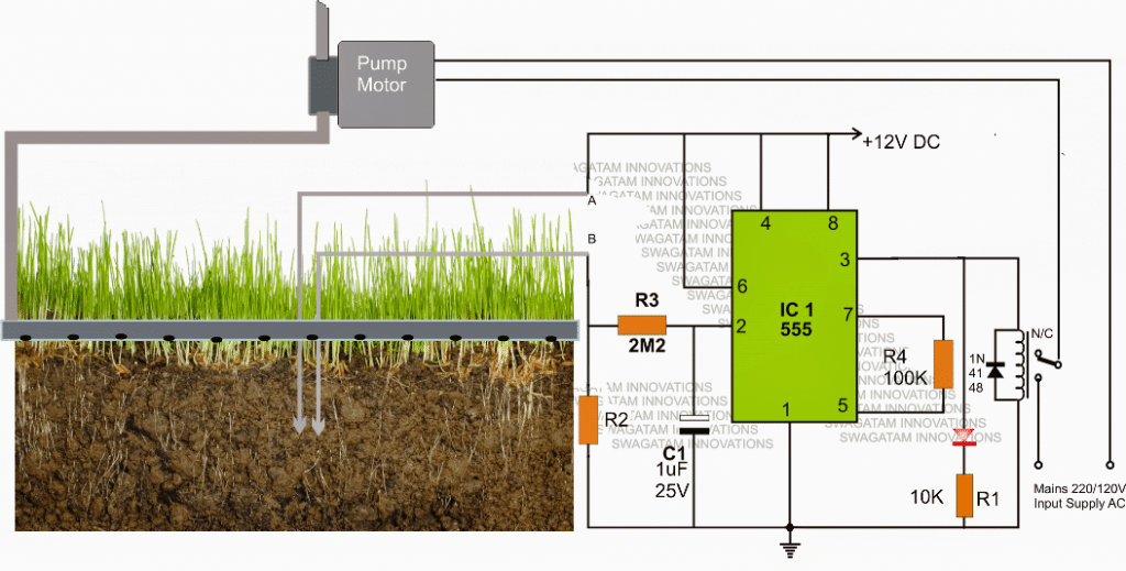
The circuit is rather straightforward and uses a single IC 555 as the main active component.Referring to the automatic plant irrigation circuit shown below we can see the IC 555 is wired in a completely unique and in the quickest possible mode.
Here it's configured as a comparator, and works better than an opamp because the IC 555 has built in opamps which are at par with any single opamp and also the output of a 555 IC is able to sink sufficient current in order to drive a relay without a transistor driver stage.
The above features particularly makes the above design very simple, low cost and yet too effective with its functions.
The pin#2 here becomes the sensing pinout of the IC, and is held at ground level via R2 which must be calculated as per the desired soil humidity triggering threshold.
The points A and B can be seen fixed inside the soil which needs to be monitored for the intended automatic watering from the water pump.
As long as the points A and B senses some level of humidity corresponding to a resistance value which may be lower than R2, the IC 555 output is held low, which in turn keeps the relay deactivated.
However as the soil tends to get dryer, the resistance across the probes starts getting higher and at some moment of time it becomes higher than R2, creating a potential below 1/3rd supply voltage at pin#2 of IC555.
The above situation instantly prompts pin#3 of the IC to become high, triggering the connected relay.
The relay activation switches ON the water pump which now starts pumping water to the particular area of the soil via a distributing water channel.
As this happen, the soil gradually gets wetter and as soon as the predetermined level is reached, the probes immediately sense the lower resistance and revert the IC ouput pin#3 to a low again switching OFF the relay and the water pump consequently.
C1 ensures a slight hysteresis in the operations ensuring that the relay triggering is not sudden or abrupt, rather it switches only after sensing a genuine response from the soil conditions.
Circuit Diagram

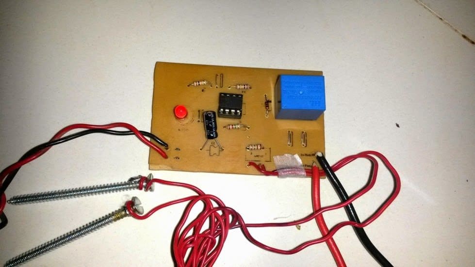
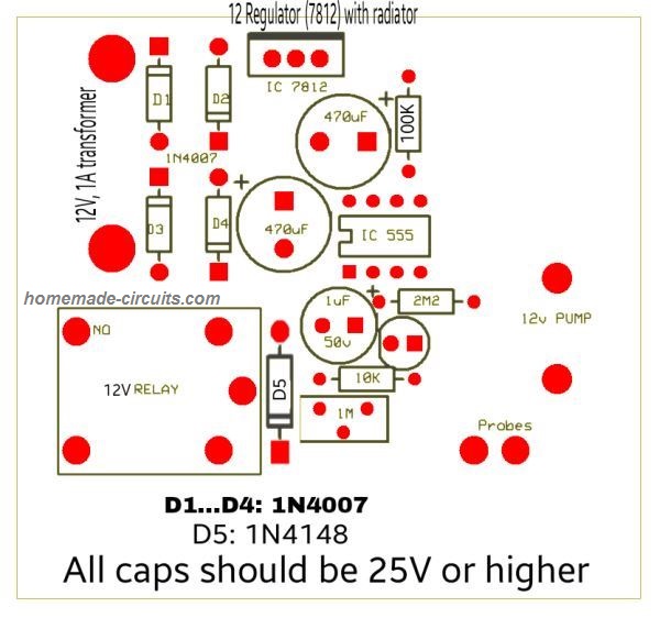
The above explained automatic plant irrigation circuit was successfully built and tested by Mr. Ajay Dussa.
The following images show the prototype unit and the PCB design built by Mr. Ajay.
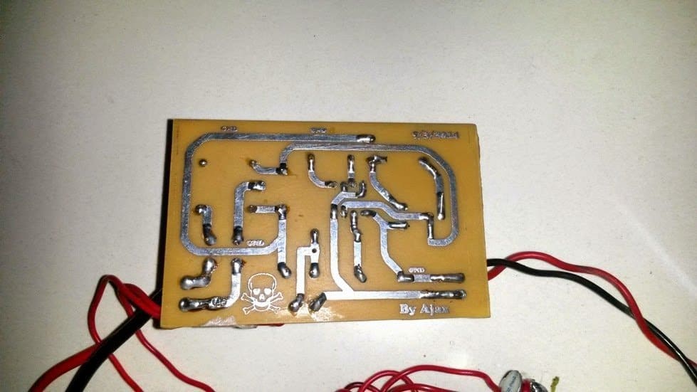
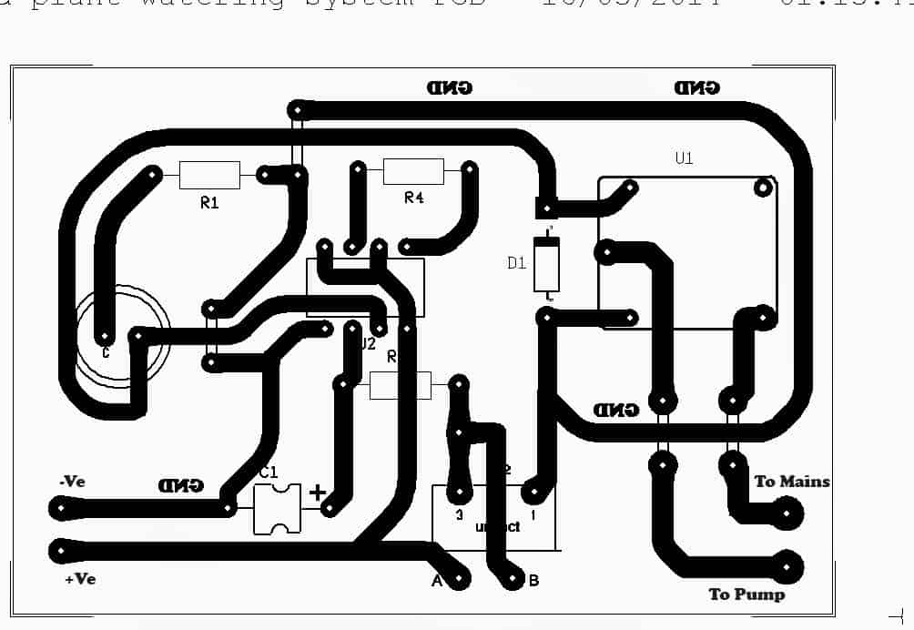
PCB Design
FOR A 741 OP AMP BASED CIRCUIT, YOU CAN REFER TO THIS ARTICLE.
Parts List
All resistors are 1/4 watt 5% CFR
- R1 = 10K
- R3 = 2M2
- R4 = 100K
- R2 = 1M preset or cermet
- C1 = 1uF/25V optional for creating delay effect on the relay
- Relay = 12V, 400 ohm SPDT
- Supply input = 12V/500mA DC
Another version of the PCB design is shown below. It was designed an contributed by: Alireza Ghasemi
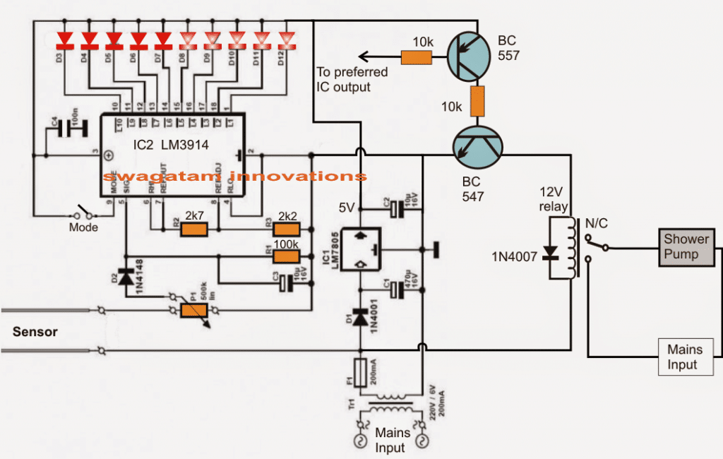
Soil Moisture Sensor with Automatic Water Sprayer
The next article explains a 10 stage soil moisture sensor circuit with an integrated automatic water sprayer mechanism for restoring the critical condition of the soil. The idea was requested by Mr. Remy.
Technical Specifications
I come today asking for help making an automatic watering circuit to water my tomatoes for me.
I am requesting the use of a soil moisture sensor (cheap eBay style) to sense the moisture of the soil.
Then the moisture value is compared to a set value from a potentiometer maybe. If level is too low then a relay is turned on for a settable amount of time. After a shower the soil is measured again.
Rise repeat.
The ability to daisy chain many together would be a great help.
For wow factor I was thinking that having a few(3) leds light up as a scale to indicate the current moisture level would work well. Thank you for your time and experience.
I have learned much from you and hope to add this to my knowledge.
Remy
Circuit Diagram
The Design
Referring to the given schematic we see a simple yet highly accurate soil moisture sensor circuit with an automatic preset water shower system for restoring the soil moisture level to optimum points.
The design is based on a single voltage sensor/LED driver IC LM3914 or a LM3915. The shown sensor pins which are basically two brass rods are configured as voltage sensors across the critical soil area where it may be inserted.
The voltage across these pins depend upon the level of moisture present across that particular soil area. This sensed voltage proportionate to the soil moisture level is applied across pin5 of the IC for the required comparison with an in-built reference voltage level.
The threshold level at which the shower pump is supposed to be switched ON is set by P1.
Depending upon this setting, the IC internal circuitry senses the soil moisture and produces a shifting sequential low logic across the shown 10 outputs starting from pin1 to pin10.
This sensed output across the relevant IC outputs are indicated by 10 respective LEDs which light up in sequence in response to the rising or depleting soil moisture levels.
Selecting Bar Mode and Dot Mode
The LED illumination sequencing style could be selected to simulate a bar mode or a dot mode by appropriately positioning the pin9 switch of the IC to either ON or OFF.
The stage comprising BC547 and BC557 constitute the relay driver stage for controlling the motor pump switching as per the user preference.
The base of the PNP transistor is appropriately integrated with any of the output pins of the IC depending at what moisture threshold the user wants the motor to be started or stopped.
For example suppose pin15 determines a particular moisture threshold level of the soil and the user feels it to be the unsafe level at which the motor needs to be started in order to restore the soil moisture, then this pinout could be chosen and hooked up with the base of the BC557 transistor for the discussed motor switching.
Once the motor is switched ON the soil is showered until its moisture level is restored to the desired level and this prompts the IC to revert its sequence from pin15 to pin14 and toward pin10, switching OFF the motor and the shower.
The above process keeps repeating making sure that the soil moisture level never goes down below the undesired parched condition.
Simple Transistorized Soil Watering System
Here's another automatic soil watering system that you can build. Its working mode is mainly the nonstop checking of soil moisture, and then responding to a drop beneath a preadjusted degree to set off the plant watering action. This design consists of a straightforward trigger circuit, that switches ON the relay RL for a degree of moisture in the soil and its conductivity which may be beneath the fixed level as adjusted by the 5 k preset.
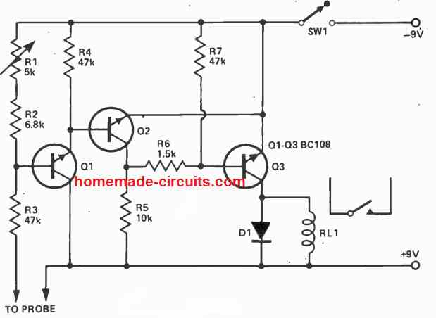
The conductivity inside the soil or mud is detected through a pair of probes coupled to the terminals as indicated in the diagram. The idea really is easy and very reliable, and will can work by using any supply voltage between 6 and 12 volts or even more, only if the supply voltage is perfectly compatible with the working voltage spec of the relay.
The relay contacts can be appropriately wired with a water pump or a water sprayer device for initiating the required automatic watering of the plant, each time a dry soil is detected and the relay is switched ON.
Using Water Control Valve
In the circuit below, whenever the amount of soil moisture exceeds a certain threshold, an electric water valve is shut off. One of the probes is attached to a positive 12-volt supply, while the other probe is hooked to the base of Q1.
The sensitivity is adjusted using resistor R4.
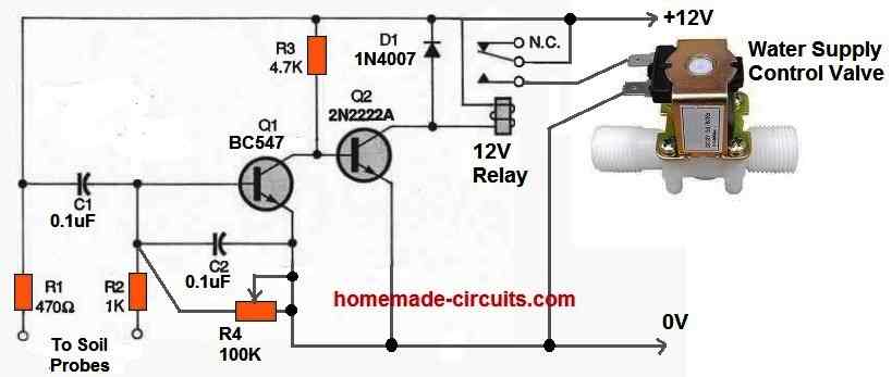
Once the moisture level falls below the predetermined level, Q1 switches off and Q2 switches on, turning ON the relay and supplying power to the water valve.
The water valve begins pouring water into the soil. When this happens the resistance between the two probes starts reducing as the amount of moisture around the probes rises.
Eventually significant current starts passing into the base of Q1 to switch it on and switch off Q2. As a result the relay turns off and the valve loses power. This instantly stops any further flow of water into the soil.
Corrosion Free Automatic Plant Watering Circuit
If the probes are not constructed from high-quality materials, electrolysis may happen and eventually impact how the circuit functions. Cleaning the probes frequently or using a circuit that uses an AC voltage on the probes are two solutions toward this issue.
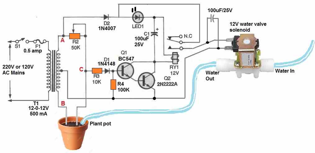
The diagram above displays an AC probe automatic plant watering valve control circuit with corrosion free probes. A 12-0-12V center tapped transformer is wired into an AC bridge circuit.
The soil or mud resistance between the probes along with R2 functions as a couple of variable components of the bridge circuit, with each half secondary winding of the transformer operating as one of the two fixed components.
In order to ascertain the magnitude of a component, such as resistance, inductance, or capacitance, an AC bridge circuit typically balances the bridge with the adjustable component and reads the component's magnitude at balance on the scale.
The output would be an AC signal which is 180 degrees out of phase and equivalent in amplitude on each side of balance.
If a typical AC bridge circuit had been employed for the anti-corrosion soil moisture detector, it would simply show when the ground resistance was close to the preset value of R4. The water valve would shut off once the bridge was balanced, but the water would still percolate into the ground, reducing the resistance between the probes.
As a result, the bridge would become unbalanced, reopening the water valve and flooding the plant soil. Not good at all.
The aforementioned circuit solves the issue by evaluating the bridge's output phase to the secondary of T1's "A" side. The relay would be activated and water would start flowing if the probes were first placed in dry soil with resistance values significantly greater than R4's predetermined resistance value.
It is because:
The voltage is provided to the relay via a 1N4007 diode and the LED whenever the "A" secondary winding of T1 changes from negative to positive.
Due to the resistance value of R4 being significantly smaller than the soil resistance, current is supplied via R3 and D1 to the base of Q1, switching it on.
However, at the same time the output at "C" is also starts becoming positive. Due to this Q2 turns on, switching ON the relay and turning on the water valve.
The bridge becomes balanced and the output voltage at "C" is zero as soon as the resistance across the probes reaches the predetermined value specified by R4. Transistors Q1 and Q2 now switch off, turning off the relay and blocking the water flow through the water control valve.
The bridge turns unstable in the opposite direction as the water seeps into the soil, however the relay is never switched ON.
It is because: Current is able to flow into the base of Q1 whenever the "B" secondary winding of T1 is positive, however no collector current is able to flow since the "A" secondary winding's voltage is 180 degrees out of phase and negative. D2 prevents that negative voltage from getting to the relay and transistor circuits.
The water valve won't turn on until the resistance measured across the probes is less than R4's value. To prevent the relay from stuttering, capacitor C1 is used to smooth out the oscillating DC power supply. Whenever the water valve is switched on, the LED flashes.
what is 1n4148 used for
To safeguard the IC 555 from the relay coil’s back EMF current
Can you share the design for this circuit.
Which design? I did not understand your question
I meant how did you get the values for all the components in the circuit.
Here we have used one of the internal opamps of the IC 555 like a comparator. R4 adds a hysteresis to the circuit and was identified through trial and error. R3 and C1 work like timing RC delay network which was also selected with some trial an error and basic experience.
The motor keeps on running even when the sensor is dipped in water.
Which resistor did you select for R2? Touch A/B points manually, check whether the relay is switching or not.
R2 = 1M , manually connecting A and B does not switch the relay, the motor keeps on running.
When you connect A and B, pin#3 of the IC should become low (0V) and the relay should deactivate to N/C points, when A and B are open or have high resistance, pin#3 should become high and the relay should activate to N/O contacts. If this is not happening then something is not correct in your circuit or the IC may be faulty.
Alternatively you can put the 1M across A and B points, and replace R2 with probe contacts and check the response.
Hi,
I just want to ask some questions.
If I need a watering timer which I could set a time(like after 1 hour), and it could continuously working until I set a new time, then what would the circuit like?
Hi, you can a one shot timer using IC 555. When you press the push button the timer switches ON, after the time has elapsed, the timer stops and switches OFF the relay.
You can find a few examples of a 555 one shot timer in the following article:
10 Best Timer Circuits using IC 555
Thanks!!!
Have you any idea for dissolve ozone meter?
Have you any idea for oxygen and humidity meter for air supply?
Please help.
Sorry, I do not have any idea regarding these concepts at this moment.
hi
i made this DIYs
thanks a lot for the idea
however,in order for the circuit to work properly i had to remove the 1uf cap otherwise the reply went on and of so quickly…like a flash…and i cant seem to regulate it accurately…its turns the relay on either when the probes are in a very low soil moisture or it goes off when out of the soil…u see? i cannot seem to regulate it to work with my desired amount of moisture…how can i regulate it more accurately? im using a 1M pot as a regulator resistant…sorry for bad english
Thanks Soheil, try adding a fixed 1 M resistor in series with your 1 M pot and check whether it improves the sensitivity or not…let me know how it works.
thanks it worked… I made a pcb myself.its smaller than yours i guess but the good thing is it also contains a built-in 12v power supply and there are 2 holes on the board which directly supply the 12v pump
tell me if u r interested
sure
in a minute
would you mind sharing the pcb layout?
sir, can i use a 741 op amp in place of 555? if yes what changes should i make?
Yes you can, an op amp circuit will work better than a 555 circuit
I landed here searchin for a circuit non-arduino neither Pi related. Thanks a lot! nowadays It seems everybody is using a microcontroller for turning on a light…….
Thanks, I agree with you, microcontroller should be used only for relatively complex applications, except in tutorial based articles.
Can I put a potentiometer in series to cable “b” to obtain a finer regulation?
potentiometer should be used in place of R2, not with the probe cable….
ok then I’m going to put a 1K potentiometer in series with the 1M preset, to regulate more finely
will do!
Hi, I would like to know what the zener diode is for, I used a 1n4007 and it was the same.
Hi , where is the zener? there’s a rectifier diode across the relay, and a LED at the output
Sir, could you explain the reason for connecting pin 5 and pin 7 together through the 100k resistor? Also please explain the mode in which the timer is operating in this circuit
Sneha, it is included in order to generate some level of hysteresis, and make sure the output does not oscillate rapidly at the cut off thresholds. It is operating in a comparator mode
what are all the components used in circuits sir ???
I have updated it in the article, please check…
If I want to control pump operation time, What is need for this circuit?
If you can, please send me that circuit. ryuma05@naver.com
you will have to insert a monostable multivibrator between the relay and pin3 of the IC, this monostable can be used as a timer for the relay and the motor
Sir, Why don't you comparator like OP-amp instead of NE555?
because IC 555 is more popular and easily available than any opamp
sir can you please tell the complete list of components of this project i am interested for this.thank you .
Hi Mark, The part values are given in the diagram itself, just copy it and show it to the parts dealer…
how can i make this function using a 12v battery instead of mains? the pump i have will function with 6-12v DC. thanks for your help.
just apply 12V instead of 220V across the points which is indicated as "mains input"
perfect! thank you for the fast reply. you are an electronics god!!!
i got this to work as intended i think…the flow of water is very slow but it might be because of the pump im using. the outlet on the pump is a diameter 5/16" outlet. any suggestions on how i can increase the flow rate? it take about 5 minutes to fill up 1 gallon.
also, i set this up using a second battery to power the pump in placement of "mains". can can i make this work off one battery where one battery will power the circuit and the pump?
thank you very much! I am glad it's serving the purpose for you.
Yes the pump diameter could be the issue, you could try upgrading to some higher specs.
Definitely that's possible, you can use the same battery for powering the pump as well as for powering the circuit.
one more question, on the printed circuit board picture above its showing 1.2.3 and a word beginning with the letter "UxxxxCT". what are these traces for and what components go there?
1, 3 for resistor, and A, B for the probes, please check out the other PCB related images and compare them for confirming
Mr Swag,
Ive attempted to operate both the circuit and pump off the same battery but no luck, can you please tell me what connections i need to make to make this work from my 12v battery? Thanks
If it's working without the pump then the problem could be due to insufficient current from the battery
In place of pump can we use dc motor
yes you can use it…
Hi, sorry I did not quite understand your question? please specify to which comment you are referring to?
Hi Swagatam,
I struggled for the last few weeks to get this circuit working with a thermistor (33k @ 25 deg). I realise this circuit was not meant for this use, but I thought I would tell you my experience anyway. So as I understand, the 555 when used as a comparator triggers at 2/3 Vcc and untriggers at 1/3 Vcc. So the thermistor, when R2 was set just right, had enough variation (to maybe 45/50 k @ 40 deg) to trigger the 555. However, with R2 in this setting, it would not untrigger, and the load remained connected. Obviously, if VR was set lower, 555 would simply not trigger.
I then asked around, and found a dedicated comparator IC, placed a transistor in the circuit, and now it triggers and untriggers. (The voltage drop is extreme though, but I won't bother you with that!)
This caused me to learn a lot about the 555 timer and its uses, and pitfalls I guess.
I only tell you this with respect, and of course your circuit was never intended for this use in any case.
I also had a question about the (revised) solar MPPT circuit. I am really intersted in this idea, but since it would be a big project for me, I wanted to ask if you are quite sure it operates as you expect. Have you tested it much?
Thank you once again, I am really learning and getting great pleasure from your page,
Regards,
Brian
PS Feel free not to post this, or to edit it in any way.
Thanks Brian, for updating the info!
yes a 555 IC will always have some hysteresis which cannot be removed completely whereas an opamp can be customized to be with or without a hysteresis, and therefore for pure comparator applications an opamp suits the best.
The solar MPPT sections are all confirmed individually, but the entire integrated MPPT design has not been confirmed practically by me, however my brain simulation says that it would certainly work, since they have been meticulously arranged and has no space to fail.
Having said that it's mandatory for every hobbyist to understand a given design first and simulate it in mind the way the original creator did….this can help a lot while constructing the circuit and in case something gets stuck, it also makes troubleshooting a lot easier…
I Wish you all the best 🙂
Hi Swagatam,
Thank you for the great and simple circuit. I am trying to run a motor in two directions to open and close a window according to heat using a DPDT relay and limit switches. I could only find thermistors in the region of 100k ohm, is it simply a matter of playing with R2 starting at 2M2 to find the right trigger value, or should a different R2 value be chosen in this case?
I also wondered if the LED functions as a blocking diode, or if it can be removed.
Thanks a million,
Brian
Tanks Brian, yes it's just a matter of playing with R2 for getting the right triggering point….2M2 is not the starting value rather an extended max range value, you can start with lower values.
the LED is for indication purpose only and has no direct role in the circuit.
R3 can be also removed as it along with C1 is employed just to generate a delay effect for the output triggering
also will the positive of the dc motor terminal go to the ic pin 3 or the negetive terminal will go there annd if so where will the other terminal go
If you are using a transistor driver then the motor will go the transistor output….and pin3 will go to the transistor base…
please what power transistor do you recommend
will depend on the pump wattage….specify it I'll tell you the exact number
Hell Mr Swagatam today one of the legs of my relay got broken. it took my a while to get that one so now am left with a normally open relay that i bought a long time ago and also a six pin dpt relay . i was wondering since my circuit is powering only a 12 volt dc pump can i connect the circuit direct to the pump terminal without using the relay. And if so do i have to change anything in the circuit or if i can still use the normally open relay or the six double throw relay. Please i need your help
Hello Kweku,
if your pump consumption is less than 150mA then you could probably connect it directly with the IC pin#3….otherwise you may need a relay or a power transistor for the same
Hello sir this is an awesome project. I am using it for my final year project. I have a 12 volt dc pump can I use it and also I have a 220 volt ac pump can I use that one ands replace it in place of the 12 v dc without changing anything in the circuit. Also is the. R3 and R2 or pot . Thank you very much
Thanks Isaac, you can use any kind of pump with the relay contacts provided it is correctly wired with the specified supply voltage, and the relay contacts are appropriately rated
sir what is the meaning of 2M2?
2.2 meg ohms
capacitor is electrolytic.
Hello, nice circuit! I'm looking at making a modified version of it… I'm using gravity fed water, so rather than a pump, I've got a selenoid water valve that needs to be occasionally held open. My idea is to make the circuit, the probes, the valve, and a 9v battery box all into one self-contained unit. Just put it in the garden, hook it up to the gravity feed water line, and then turn the probe on. Multiple probes can cover multiple zones of the garden, each with its' own sensing and delivery mechanism, independent of others. Can you make any suggestions to help pull it together?
Thanks!
Yes you can implement your idea using the above circuit, no issues, however the 9V battery would need to be Li-ion or lead acid SMF type for ensuring a longer operational time, or may be you can have a central solar panel to operate all these circuit from the source without having to worry about charging or replacing the battery often.
you may also go through the following related article:
https://www.homemade-circuits.com/2016/01/precision-water-management-in.html
What is resistor specification?
all are 1/4 watt
sir… What is the value of R2, R3?
and where should the led be connected?
you can use a 1M pot for R2…R3 is shown in the diagram, click it to enlarge.
Dear sir…if u dont mind can u Please give me the complete list of components… And exact operation of the circuit……its very urgent to me…hope u will reply soon
Dear Nandini, ample explanation is already provided in the article and the comments, please go through it.
all resistors are 1/4 watt 5%
IC can be any 555 IC
relay is 12V 400ohm SPDT
supply voltage should be around 12V DC from any standard ac to DC adapter
Hi sir ,i want to build this circuit but the question raises that IC 555 timer is used to get output high or low for a particular time which can be set using resistors but in this circuit we are using soil as our parameter to select time for which our timer should on ,how it is possible?
Why there using R2 and R3 .If we are uaing R2 as our refrence resistance then why there is R2 is used?
Sir i have question that which sensor i have to use here ?
Which type of relay is used here? SSR or EMR?
i have these questions ,plz sir reply me through mail as fast as possible.. Thanx for giving such a simple circuit..
Hi Sudin,
It's not the resistance rather the voltage dropped by the resistance which determines the triggering point for the IC….so here the soil also leaks and provides different voltage levels depending on its wetness, which is sensed by the IC for the required triggering.
sensor is in the ofm of stell rods.
R3 is for allowing a time delay response in conjunction with the capacitor to the output triggering.
relay symbol clearly suggests it is an electromagnetic relay
correction:
sensor is in the form of steel rods.
Thanx sir giving me ur valuable time .plz tell me sir how to adjust threshold level 2/3VCC Above which IC will give output low and 1/3VCC below which it will give high output ..
There's only one pot which you need to set for triggering the relay at the threshold….basically here the IC is configured as a comparator, the 2/3 feature is not used here.
I have explained it in the comments and the article, you can go through for knowing more about the details.
Sir,may I know if I can use a DC motor instead of an AC motor in this circuit. If it's possible please tell me how the connections are to be made for DC motor?
Gokul, yes you can do it simply replacing the lower relay contact with +12V supply and the motor wire with -12V of the circuit
Hi Swahatham, Iam a Electrical Engineering student from Bangalore. This circuit is quite simple and very useful! So I want to build this and implement this in my terrace garden. So.. If at all I want to water more than 2 pots of plant then how do I male changes in the same circuit shown above?! Awaiting your reply Thank You! 🙂
Hi "unknown",
for two or more pots, you will require two separate circuits because since the two pots won't be linked so the sensors from one circuit cannot be used for the two pots….the soil must be linked with each other in order to enable sensing with a common circuit…otherwise two individual circuits would be required for each of the pots
Firstly I would like to thank you very much for providing this simple and very useful circuit for students like us.
By the way we have selected this Automatic Water Planting circuit as our project and It is working too. We have used 2M2 for R2. But the problem we are facing is our circuit sensing the moisture very quickly. Even it does not let water pump to start. When we remove the spikes from soil and short them manually, it is working correctly. But when we insert spikes in soil it senses very quickly and doesnt let water pump to start. So, please guide us as early as possible.
Thnx
Ankit Patel
ankitpatel7586@gmail.com
00642102848545
I am glad you found this circuit useful, however I am confused regarding how the circuit is detecting the moisture without the pump switched ON? Do you mean to say it's sensing the existing soil moisture??
In that case the soil needs to dry further…or may be the distance between the sensor rods could be increased until the the problem looks corrected.
Another option is to increase the value of R2 to higher level until the right balance is achieved….may be a 3M3 resistor could be tried to reduce the sensitivity of the circuit.
Hi, I am a student at and am very interested in doing research on crops in the south of the United States. The problem is, I don't have the ability to hire someone down there to water the crops, and it is too far for me to travel to. Would I be able to buy this product from you? Or how can I go about obtaining it? Thank you so much. You seem like you are a brilliant man.
Thanks Malorie, I am sorry I don't sell circuits here, so this may not be available from this site. However I am sure there could be other online stores who might be selling such circuits in their sites, you could probably Google it for more info……
will you please tell me ic 555 is operated in which mode here? astable,bistable or monostable??
comparator mode….
hello,
I make this circuit, It is working very good.but in this circuit i want to use 12v 10amps relay for( big moter)
in this circuit i m getting 6v output for relay, than how it is possible to connect 12v relay? So how to convert 6v to 12v(for relay),
i think i have to connect transister for get high voltage .
what i have to do?????
thanks,,
if your supply voltage is 12V then definitely you'll get 12V at pin3 of the IC.
however you can connect a BC547 transistor and use the relay across its collector and the positive supply to ensure a perfect working of the relay.
the base must have a resistor of around 10k value
Hello
I have been seeing the circuits your circuits and quite impressed by it, this one is my favorite, i have built it on the breadboard and tested it works great. I didn't had 2m2 ohm at hand so i managed to combine 4 resistors 2x 1m + 2x 100k, while you said to set the moisture density threshold we need to use 2m ohm and less until the led goes off, i first used 2m pot it didn't worked, then 500k also didn't worked the used 100k it worked, measured its resistance it was 23k, the led goes off at 23k when the soil is fully wet. I have currently tested it in a small jar with soil, i wanted to ask if i were to put it in a plant pot as this one s23.postimg.org/jbhcleye3/172279916_potted_cactus_gettyimages_jpg_v_1_c_IW.jpg, what should be the distance between points A and B and where they should be placed in the pot so that there will be enough time for pump to water the pot/plants before the resistance decreases and it switches off.
One more thing, somebody suggested me that a transistor should be added to at the end of the point 3 of 555 to smoothen out the relays, do u think a transistor is necessary, i don't really feel the need of transistor after all my testings. Anyway i really like this circuit. Thank you
Regards!!
Thank you very much, I am glad the circuit worked and is serving the purpose.
The R2 needs some experimentation, if 100K is the value that works then you can use it without issues.
you can use the circuit for monitoring the soil in a small pot also, the distance between the sensor probes should not be more than 3 inches for an optimal response
a transistor stage may not be required because the IC itself is rated to handle upto 200mA which is well above the consumption of any standard relay
It will work, but not with just 2nos of 1.2 cells, you might require 4 or 5 in parallel to increase current.
yes the flyback ferrite core can be used for the said purpose, it would in the form of E cores I presume.
It is in rectangular shaped, two half's of ferrite core are joined together by a piece of hard metal wire. What i have looks like this image https://sites.google.com/site/sparrow338/IMG_2290.JPG
Anyway if i were to wind coils on it, should i wind using the usual transformer winding method, each winding on top of one another or the HV secondary on one side and primary and feedback on the other? Would it make any difference in the power output?
It will do, the winding pattern is not critical, you can either wind them over one another, or over the adjacent arms of the core.
hello sir what is the watt or the resistors?
all are 1/4 watt rated
good day sir
when i apply 12 v at the circuit my water pump also started.
then my ic 555 suddenly heat up
is my ic 555 defective?
also the led is not working also in the circuit
but when i test LED individual it is working
please help me
thanks a lot
Wil, what is your relay coil resistance? if you are using a big relay you will need to use a transistor stage for operating the relay at pin3 of the IC…..it may be getting hot because of a low resistance relay (heavy relay)
the label in my relay erased already, but i remember it is 12 v .
i dont know the coil resistance.
what would be the relay i need in this circuit ?
thank you in advance.
i use 12v power supply, 3 ampere
what should be the coil resistance must the relay have ?
thanks:)
i measure the resistance coil using ohm meter and it measure 250 ohm
i mean 400 ohm
400 ohm is perfectly OK…so the problem could be somewhere else….or may be the IC could be damaged.
check voltage of the supply source…must not exceed 15V.
what is the code for relay
can be a 12V, 400 ohm, SPDT, 5 amp relay
can u give me ckt. of automatic humidity control…………..
plzzzzz …………………
you can try this one:
https://www.homemade-circuits.com/2014/03/programmable-humidity-controller-circuit.html
hi sir….
what is value of r2…..??
it's missing………..
Raj, you must use a 2m2 pot in place of R2 so that you are able to adjust the sensitivity of the circuit
hello sir my circuit work perfectly but it soil moisture sensitivity is to high when soil moisture is less then 10% then it will be work help me i want when soil moisture is 40 % then it will work i use 6vdc relay
hello faizan, increase the value of R2 to some higher level, keep increasing and checking the results until you have found the right value for R2.
hey sorry for all the questions but i could not get it working, i think my ic555 chip was defected so i build a circuit to test this other chip i had and it seems to be working!. soo im going to try once more. im confused on replacing r2 for the pot where to i place the wiper and what value of red led is that 3v?
use a 1M pot for R2, use only its center and any of the outer leads, the third lead can be left open.
the LED can be any ordinary 5mm/20mA/2V type
it's not critical any closer value would do, it's just for providing the IC some time delay before it responds to the soil conditions..
damn, i cant find a 1uF Cap is there anything else
The cap is not polarity sensitive correct?
yes that's correct
Are both the diodes in the scematic the same? And are the zener diodes? Also I have a 1n4004 and a 1n4001 will the work?
Hey love the circuit, my only question is are both the diodes in the schematic zener diodes, also I have a 1n4004 and 1n4001 diode will they work
Thanks Josh, the red one is an LED, the black diode can be a 1N4007
1n4004 will also do instead of 1N40007
The phase goes to the relay contact….neutral directly with motor
For C1 1u 25V ,can we change capacitor to 1u but 50V.does it effect to this circuit???
It will do.
Motor ac or dc???
AC
Near the diode there is a winding.
Is it inductor and there is a switch alsoo.
that's a relay. the inductor is the relay-coil, and the NC is one of its contacts
Motor ac or dc?
Hiii
In my place the single winded auto transformer is not available. So is there any option which I can replace instead of that.
Hi, there's no auto transformer used in the above explained circuit, so I am not sure where you intend to use it and why?
Above the input
It is acting as a switch N/C
What is the device used there.
There is winding near N/C what is that winding sir.
There is a winding near diode.
There is a switch.
What is that winding near the diode sir..
Hii
I want to know all the components which are in the circuit.
At the output I am not knowing the components which are used.
Please tell me which components are used.
Hi Please click the diagram to enlarge, all the components are appropriately listed in the diagram itself.
The relay is a 12V SPDT
hello sir, may i know whats the use of resistor connected between pin 5 and 7?
hello sonny, it's for creating some degree of hysteresis in the IC functioning…
can I know this circuit used microcontrolled(PIC) or not to control the time process?
there's no time factor here, and no microcontroller used.
hye,sir
im electrical engneering student.
Im interested to do this project as my final project.
please send me information, complete project detail and programming details.
sankancu1724@gmail.com
Hi sankar, everything's explained in the article and the diagram, please click the diagram to enlarge for getting a clearer view.
Hi sir can you help me how to calculate R2 in the circuit dry soil=1.7M ohms and wet soil=0.7M ohms and what should I include in my design report I was designing the soil moisture sensor.Thank you your circuit is very useful
Hi Sanele,
you can use a 2M preset for R2, connect the probes in a wet soil and adjust this preset until the LED and the relay just switch OFF
you ca try "potential divider formula" for getting the R2 value mathematically,
Sir, by the way, I wanted to use a transformerless power supply for this circuit, can I do so sir,…? I would be happy if you could suggest a transformerless power supply circuit from this blog…also please tell me the current consumption of this circuit…….thank you sir……
SS, it would be better to buy a 12v/1amp smps adapter from the market, a capacitive transformerless power supply could carry lethal mains AC due to its non-isolated topology.
for reference you can see the following design:
https://www.homemade-circuits.com/2011/12/cheap-yet-useful-transformerless-power.html
Oh…! Ok….thamk you sir…could you tell me the current consumption of the circuit sir,….thank you very much…..
it would be equal to relay current + 5mA
Dear sir,thank you very much, i followed your advice……and used 12v 1amp adapter(looked safer and better….:))….by the way, ive seen the circuit "earth leakage indicator circuit….thank you very very much sir…..ill make the circuit soon and give you the photos………….
thanks and regards..
ss.
Thank you dear SS, I appreciate it.
Dear sir, thank you very much…….I've seen the circuit……no problem………you may design the the buzzer indication circuit when you are free and hav time….designing this circuit for me is not as important as doing your works…..but you're more concerned about others…….you're a boon to the electronics society all over the world…..and to people like me….
thank you very much,
ss.
Sure SS, as soon as I am free I'll upgrade the circuit appropriately:) I appreciate your involvement very much.
This is a very useful circuit sir, just made and installed it in my house, works very great. I've seen other circuits online…..but as always the best circuit with more affordability and durability is here….thank you for your innovative innovations….:-)
Thank you SS, I appreciate it a lot!
By the way I have published the phase neutral indicator circuit, but it's not as efficient as the original, because due to lack of time I couldn't experiment enough with it.
Nevertheless the results from it would be perfect.
o o thanks bro.
how can i make battery indicator of 5 leds for 12v battery.
….you can refer to this article, it's a 10 LED circuit:
https://www.homemade-circuits.com/2013/08/make-this-10-step-battery-voltage.html
Hi Mr swagatam,
i am new to your website and happy that there are so many good circuts,
I am in a instrumentation field, presently on some small project which need a 3.7vdc 750mAh lithium ion rechargable battery as a back up power, so kindly let me know the one good working circuit for 1)overcharge protection 2)immediate change over 3)low battery indication. As the one like yours Automatic micro UPS circuit.but now its for 3.7vdc
Bro, The input is not 3.7V, the requested circuit is for charging the 3.7v cells….
for charging 3.7v cells the input has to be 5v,
the diode cathode will obviously connect with the positive of the cell.
Oh!!!!Thank you for this circuit.Was waiting for this one.also I had sent you a mail on hitman2008@live.in regarding water controller.Please check that out.Also can you mention the value of R2…..I think it's missing….
You are welcome Ajay!
I have replied to your email, pls check it.
R2 can be replaced with a 2M2 pot for setting the soil moisture detection threshold.
HI am trying to implement this one with 5v / 6v power supply? What is the red button there, is it a LED?
yes it's the LED, please click on the diagram to enlarge it.
Sir, is the R2 here a potentiometer?
Kristina, it can be a pot or a preset, it depends on how you would want it to be used