Here I have explained about a circuit configuration which produces adjustable sequential timing outputs for controlling a heater device through a simultaneously sequencing temperature controller circuit which can be also pre-programmed for acquiring the desired temperature levels across the sequencing time slots. The idea was requested by Mr. Carlos
Technical Specifications
I’m Carlos and I live in Chile.
As I see that you have the willingness to get us out of trouble with some electronic circuits, I would ask if you have any circuit that controls the temperature and time simultaneously.
What I need is a controller with programmable temperature timescales. For example you first hold a temperature T1 at t1 minutes, at the end of this t1 maintains a temperature T2 for t2 minutes after that maintains a temperature T3 for t3 minutes.
The temperature and time should be adjustable in a simple seer either via a PIC or the like, but must be capable of being adjusted without being re-programmed by means of a PC.
I stay eternally grateful.
Best wishes
The Design
The first requirement as mentioned in the above request is a programmable timer which would be able to generate a sequential delay ON periods through a serially connected timer modules.
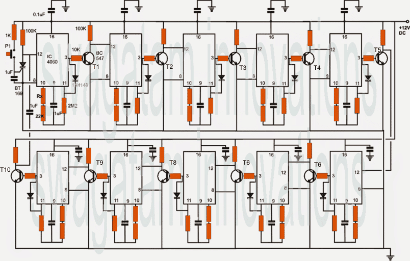
The number of timer modules and time slots will depend on the user and could be selected as per individual preference. The following diagram shows a 10 stage programmable timer stage made by using 10 discrete 4060 IC stages connected in a sequential configuration.
The design may be understood with the help of the following points:
Referring to the given diagram below, we are able to see 10 identical timer stages consisting 10 nos of 4060 IC arranged in a sequential switching mode.
When the circuit is powered and P1 pushed ON, the SCR latches on resetting pin12 of IC1 to ground initiating its counting process.
As per the setting or selection of Rx, 22K and the adjoining 1uF capacitor, the IC counts for a predetermined period after which its pin3 goes high. This high latches itself through the 1N4148 diode and pin11 of the IC
The above high at pin3 of IC1 activates T1 which resets IC2 pin12 into action and the procedure repeats carrying forward the sequence to IC2, IC3, IC4...until IC10 is reached, when T10 resets the whole module by breaking the SCR latch.
Rx may be replaced with a suitable pot for acquiring the desired delays discretely across all the sequential 4060 stages.
Circuit Diagram


The above configuration takes care of the required programmable timing control, however for obtaining correspondingly sequencing time-scaled temperature control, we need a circuit that would be able to produce precise, adjustable temperature outputs.
For this we employ the following configuration in conjunction with the above circuit.
PWM Temperature Control
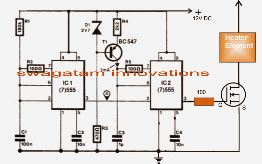
The shown temperature controller circuit is a simple IC 555 based PWM generator which is able to produce PWMs adjustable right from zero to maximum depending upon a external potential at pin5 of IC2.
The PWM content decides the switching period of the connected mosfet which in turn regulates the heater element at its drain ensuring the required amount of heat in the chamber.
The mosfet will need to be selected as per the heater specs.

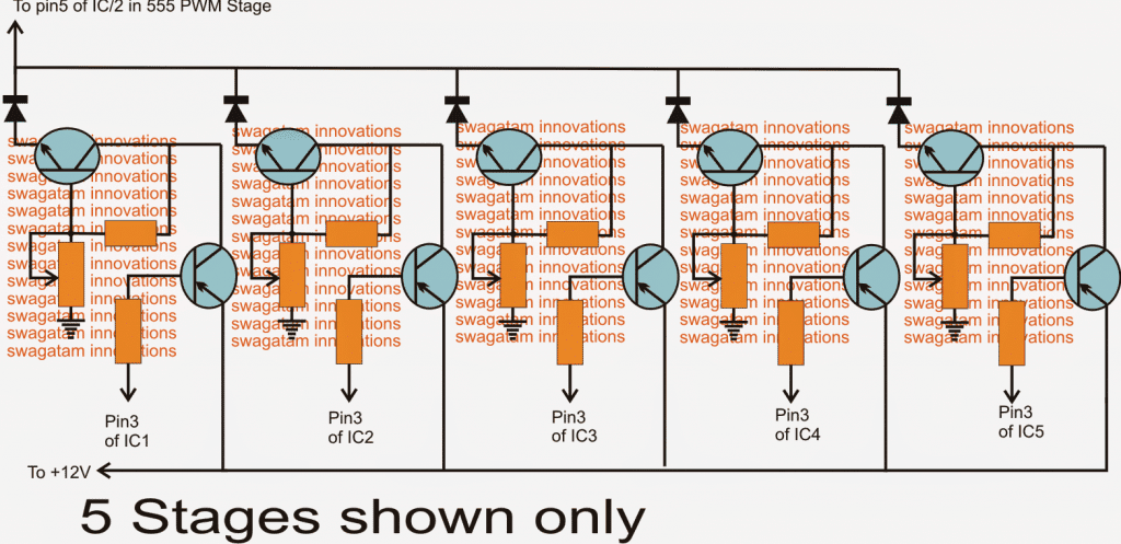
The link between this PWM stage and the above sequential timer stage is determined by an intermediate stage made by configuring a common collector NPN device along with a PNP inverter stage, which may be seen in the diagram below:
Integrating PWM Temperature Controller with Timer Circuit

Five stages are shown in the diagram which may be increased to 10 numbers for integrating with the 10 stages of the first sequential timer circuit.
Each of the above shown stages consists of an NPN device wired up in a common collector mode for enabling a predetermined magnitude of voltage to be obtained at their emitters, which would depend upon the setting of the base preset or pot.
All the emitters are terminated to pin5 of the PWM IC2 via separate diodes.
The PNP devices work like inverters for inverting the counting low logic at pin3s of the sequential timer stages into a 12V supply for each of the common collector stages.
The pots here may be adjusted for feeding the preset amount of voltages to the PWM stage which in turn will regulate the PWMs to the mosfet and the heater device, generating the relevant amount of heat for that particular time slot.
Thus in response to the relevant timer stage switching, the corresponding common collector NPN gets activated producing the set amount of voltage at the pin5 of IC2 of the PWM circuit.
Depending upon this preset voltage the heater outputs gets regulated via the mosfet switching.
As the timer sequences, the heater temperature is switched to the next predetermined level as set by the base presets of the above common collector stages.
All resistors in the common collector circuit are 10k, the preset are also 10k, the NPNs are BC547 while the PNPs are BC557
Thanks and God bless .
Hi Swagatam
This post is not written/submitted by me 🙂
Thank you Abu-Hafss for notifying it:) I have corrected it now, it was probably some glitch from me while editing your recent post.