In this post we try to investigate a couple of innovative solutions which could be used for pausing the counting process of a timer IC during power failures, and also restart the process when mains is restored, ensuring a continuous functioning of the timer without errors. The idea was requested by Mr. Arun Dev.
Technical Specifications
I need a timer circuit which should activate a relay for the determined time interval and thereafter deactivate it until a manual operation is detected...
The main purpose of doing this circuit is to charge my laptop or mobile phone over night keeping it charging for a few hours ( say max. of 4 hrs ) only......
thereafter charging cut off immediately.... even though the main intention is for charging, i also want to integrate this to operate a particular electrical equipment as per user's time decisions....
This can easily be carried out using a relay to switch the AC voltage as seen in the attached figure.....
but the only one problem regarding this is that :
whenever a power failure occurs during its ( timer ) working period, the CD4060 IC automatically gets reset and the timer starts from beginning when power returns.....
SO ANY IDEA TO PAUSE THE WORKING ( COUNTING ) OF THIS IC DURING POWER FAILURE AND RESUME FROM THAT POINT WHEN POWER RETURNS TO MAKE SURE THAT THE CONNECTED EQUIPMENTS ARE WORKING ONLY IN THE USER DEFINED TIME ??
Circuit Diagram

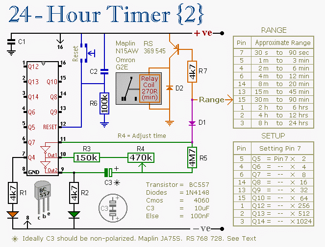
The Design
The modified version of the above 4060 timer circuit can be witnessed in the following schematic. The circuit includes an automatic pause and restart feature of the IC's counting process during power failures and restorations respectively.
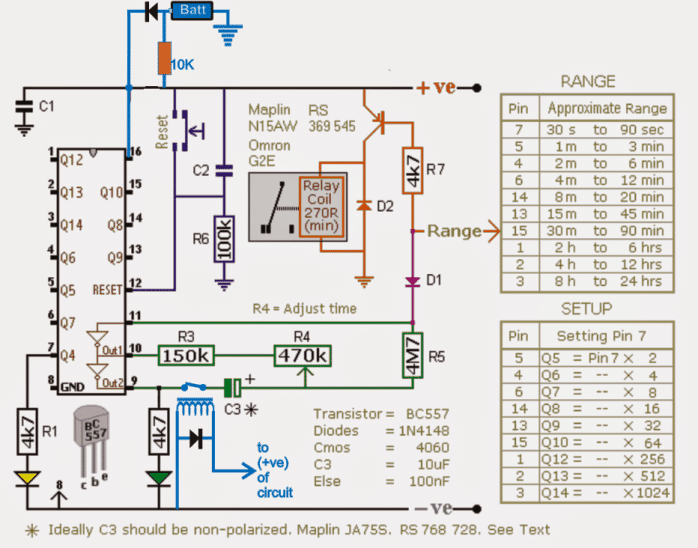
The sections which are colored in blue are the inserted modifications, we can see a battery backup being added at pin16 of the IC via diodes, and a relay at pin9 of the IC.
Since the capacitor C3 is responsible for initiating the counting process of the timer while it gets fully charged, this component could be targeted for the intended pausing/resuming of the timer.
As may be seen in the diagram, this is simply implemented by connecting C3 to the "hot" pin9 of the IC via a pair of relay contacts (N/O to be precise).
However for making the above implementation work, the IC needs to be supplied with its fundamental operating current and voltage while the mains is not available.
This is done by adding a battery back up to the IC via isolating diodes at pin16 of the IC.
The associated 10K resistor makes sure that the battery keeps getting the required trickle charge as long as the mains continues to be present.
When power is first switched ON, the relay at pin9 activates and connects C3 in the line so that the IC is able to initiate normally and begin its counting process.
During Mains Failure
In an event of a mains failure,the battery takes over and keeps the IC powered in an uninterruptible manner, while also simultaneously the relay at pin9 of the IC disconnects C3 from the line in order to stop the capacitor from losing the stored instantaneous charge via pin9, this ensures that the elapsed time period gets locked inside the capacitor for that particular moment until the mains is restored.
The moment mains power returns C3 is connected back with the circuit by the relay, enabling it to resume the counting process exactly from where it had stopped and not from zero as it would otherwise do if the above mods weren't included.
The above could be also identically implemented in other timer ICs such as in IC 555 monostable circuit or IC 4047, IC 556 IC 4022 etc.
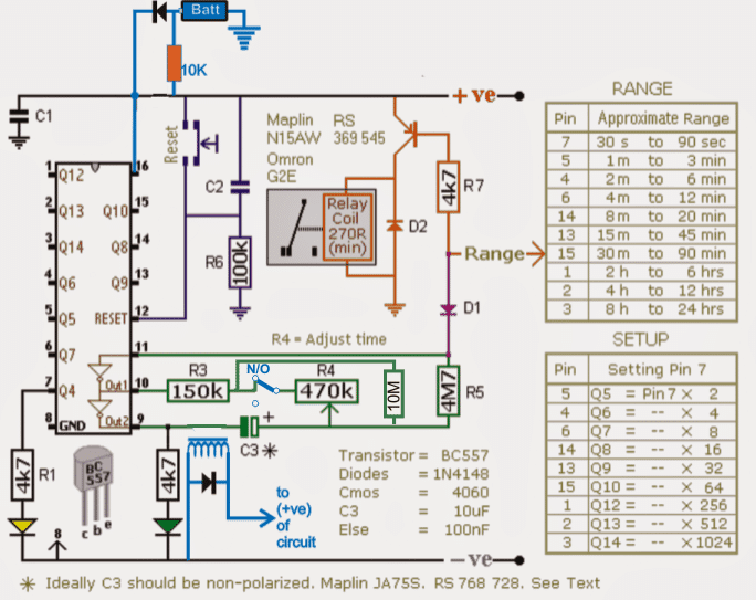
As discussed in the comments the above designs may have some limitations and flaws, a reasonable approach may be witnessed in the below given diagram which would hopefully allow minimum discrepancy, not more than 1% +/-. See the relay connection in blue across R4 and the inclusion of the high value 10M hold resistor.
Design#2: Timer Circuit with Memory
In this post I have explained a timer circuit programmed to cycle at 60 minute interval for watering the fields consistently. It also includes a time "memory" feature which ensures that the timer "remembers" the counting during mains failures, and restarts exactly from where it was interrupted when mains power is restored. The idea was requested by Mr. Siva.
I want to utilize the bore-well pump ground water based on online AC power supply.
stage 1:
1) Timer A start from zero end with 60 minutes(1 hour). 2) output power supply provided to stage 3 contractor coil. 3) Timer A should resume where it stop (e.g:stopped after 10 minutes successful running it should resume from 10 min until step 1 complete) 4) After 60 minutes completion it will stop & stage 2 will start running.
stage 2:
1)Timer B start from zero end with 60 minutes(1 hour). 2)Timer B will have inbuilt power supply(eg: AAA size rechargeable battery) 3)After 60 minutes completion it will stop & stage 1 will start running.
stage 3:
- 3 pole contactor used to allow the AC power supply. 2) Contactor coil power supply received from timer A circuit. ------------------------------------------------------------------- I) There is an frequent power failure in our area. II) Can't run the pump at an desired interval time period. III)For agriculture use only. IV) Pausing a timer during a power failure could be difficult using discrete components. V)suggest me any other components available in online. VI)I am ready to purchase it.
How it Works
The stage#2 timer circuit is perhaps not required since the stage#2 alone can be used for implementing the 60 minute ON/OFF cycle for the motor.
The main challenge in the design is the pausing of the timer IC such that the timer circuit is able to freeze itself during a power failure and initiate the timing from the same point as soon as the power is restored.
This seems a little complex since the IC might require some kind of memory feature to remember and retain the time period for which it was stopped due to a power failure.
However, with a simple trick it may not be so complex to implement the mentioned time pause effect, and could be done simply by cutting off one of the timing capacitor leads during mains interruptions, and then joining it back once the power came back.
The following diagram shows the set up, which will hopefully be able to perform the intended pause effect in the timer circuit.
Circuit Diagram
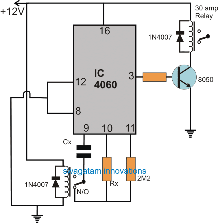
The design is nothing but a simple IC 4060 timer circuit. The Cx, and Rx form its timing components, meaning altering the values of these proportionately alters the output frequency timing at pin#3 of the IC.
A low current relay can be seen attached with the timing capacitor of the IC whose contacts keep the capacitor connected with the circuit configuration during normal operations or when mains power is available. However in the absence of mains, this relay quickly cuts off the capacitor from the circuit.
Since the charge content inside the capacitor fundamentally determines the time delay periods across the outputs of the IC, disconnecting the capacitor enables freezing of the charge content inside the capacitor intact until the power arrives back.
As soon as power gets restored the IC reads and responds to the available charge inside the capacitor and initiates the counting from the same period onward where it had stopped. This system ensures that the IC resumes from the point where it was stopped due to the mains interruption.
The output pin#3 of the timer is connected with a 30 amp relay stage which may be configured with the contactor unit, for the necessary triggering of the pump and for watering the farm at the specified time intervals.
The timer circuit is designed to cycle ON/OFF with time delays as set by the values of the Cx and Rx, which may be calculated using the formula presented in this simple 4060 timer circuit article:
Hi, I have a 12v battery charger. When I got it parts were missing. I Hope you can help me with values for c5,c7 ,t1 and t2. I can’t find any information other than what I have in the picture. Thanks for your help.
https://drive.google.com/file/d/1dCaWGQtOSNfCBIuUcDx7TgJxDp5hgF-Q/view?usp=drivesdk
Hi, the G drive link is not in the “shared” mode, so I cannot access it, please change it to the shared mode…
Hi. Swag
I have a question about the 24 hours timer.
This moment i use them for my aquarium light installation to delay the power going in to the faders.
My question is as follows , is it possible to replace the relay with a power transistor or a mosfet for switching max 1.5 to 2 amps.
i use the 24 hours timer 2 for this installation and it works fine but i want to make the whole installation a bit more compact so it will fit in a normal housing.
If this is possible can you put an example in de schematic how to do this.
The relay is switched by the positive power line and i like to keep it this way if possible.
I hope you can help me out because i try it myself and did not get it to work.
The relay is now switched by a BD140 transistor and the replacement for the relay needs to switch another power line than the timer use.
Tanks in advance.
Johan.
Hi Johan, a mosfet or BJT may not provide good results because the timing capacitor of the IC needs to be operated bidirectionally, so the control switch will also need to be bidirectional.
May be a small SSR can be tried instead of the relay. I would rather go with a relay which may be very tiny in size as shown below:
" rel="ugc">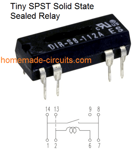
hi.
to bad that it will not work because i want make it totaly on a 20×20 cm pcb.
on this moment it is 30×20 cm and will not fit.
maybe it can be done with a combination of SMD and through hole components but i am not so good with SMD soldering.
thanks for looking in to it for me and i keep on thinking how to do it in another way.
Johan.
OK, no problem, in that case may be you can try a BJT NPN, and see if it works or not, luckily it may work, I am not exactly sure!
Raja, if the relay is not allowed to operate then your battery could last for days, since the current consumption of the circuit without the relay is not more than 5mA
the relay could be stopped from activating during the battery back up by connecting the battery positive with the circuit through a resistor….a 10K will do.
8V will be more than sufficient
Hello Raja, thanks very much!
if you are using a battery as a back up source, then it becomes absolutely easy to maintain the counting process without any kind of interruption even during power failure.
No modifications would be required in the circuit except the pin#16 connections, which will need to be wired with the battery exactly as indicated in the diagrams.
Hi !
I don't know how to ask this , but i guess from the following words you'll understand what I mean.
" I want to make system ( amplifier) which will have delay power on for 5sec(adjustable). During that delay period, another circuit will be working led chaser. The amplifier will be powered by a push button switch (whatever N/O or N/C) "
Working : consider the following;
A as push button (on/off with LED green/red)
B act as a loading effect (LED chaser ,,10-12 LED)
C power amplifier (wait 5sec after A pushed)
Once plugged in, the system will be at standby mode ( with red LED on), when the power button is pressed , B will start working for 5sec only (adjustable) after Delay period , C will start to work. B should remain off until the system is restarted.
those circuits can be operated by 6-12dcv, preferred single supply if possible
you can use the following circuit:
https://www.homemade-circuits.com/2013/02/make-this-simple-delay-on-circuit.html
the relay pole should be connected to the positive supply….N/C to the chaser positive, and the N/O to the amp positive.
the above circuit will be need to be switched ON using an ON/OF switch, a push to ON might not be applicable here.
one led can be connected in parallel with the relay coil with a 1k resistor
Dear sir
Can you please send me the schematic of the working circuit
Email:[email protected]
Thank you
Dear Ali,
Please check out the last diagram updated in the above article, which may possibly carry out the implementation reasonably well as intended….
plz check your hitman inbox sir ..
hai sir….. i have sent you a mail ( to [email protected] )2&. . plz check it out and give me a solution
Hi Arun,
I'll check it tomorrow…
Finally the problem has been solved sir….. modified diagram has been sent to you…. you are requested to check it out
I have answered your email! please check it,…
sir….i got your reply mail…… thank you very much….. now let me modify it….. i will get back to you soon with the new results
You are welcome Arun!
The idea z nice sir ….. but why it z necessary to know the mains off time ???
This circuit is set for predetermined time duration ( say 5 hrs set by 2M2 in place of the pot )….. let us assume that main fails after 3 hrs……. the power cut is assumed to be 4 hrs….. then if we are placing the entire circuit for operating for 5 hrs initially without knowing about any such power failure which z gonna occur in the nearby future, then the following will occur :
CASE 1 : timer stops operating after 3 hrs ( when power goes ) and will be idle for 4 hrs during power failure
CASE 2 : Timer continues operating during power failure and will get turned off after 2 hrs…
in both cases whatever it be why it is necessary to know the mains off time ?
yes the mains off time cannot be used, won't serve any purpose here, i just thought quickly and tried to provide an example of the type of remedy that may be suitable, it wasn't a final thought or design from me.
I will require some thinking….
Happy independence day sir…..
hope u have read my last email… another thing to inform you is that ; i have also tested this circuit by giving a possitive signal to the diode D1 during power failure….. it worked….but sometimes that given signal is being latched in the diode side even after power returns similar to the problem discussed in my email…..also whenever it is functioning, the remaining time duration just after the paused state not attains the target time
I haven't checked your email yet, will do it soon…
we'll have to figure out some out the way solution for solving this….may be add another circuit that would add the mains off time with the 4060 set time for compensating the lost period…something of that sort.
i have sent u a mail regarding this timer…. could u plz check it out sir ????
Sir this config. will never work….. i have tested it practically….. because, whenever the contact between the Capacitor terminal and PIN#9 of IC cuts during power failure ( keeping the ic working under auxiliary battery power ) the Voltage at pin#11 of IC becomes high automatically thereby counting ceases….but the problem is ,that pin remains at high state even after power returns keeping the oscillations ceased eventhough the capacitor contact is getting joined with pin#9 again……so it requires a reset for a new counting to begine
Arun you can try replacing pin10 of the IC instead of pin9 with the relay contacts and see the response from the IC….because as per the internal schematic of the IC this modification could result in locking of the oscillation and also stop the capacitor from discharging further.
Sir, i have tried everything as you suggested…but still the OSCILLATION in IC is getting freezed in its paused state even after power supply returns…. Disconnecting the capacitor lead from pin#9 of IC as in this article also didn't give the intented results…. the IC was also in the freezed state in this case….
One thing i have noted is that, Oscillation in CD4060 is getting resumed iff the duration of power failure is very short ( say 1 mnt )…. in all other cases the IC can't resume its Oscillations…
Arun, can't say much until I check it myself….in the meantime you can try the same with a 555 IC by disconnecting the capacitor from it. If it works, it's timing could be easily amplified with a 4040 IC for getting any delay duration
Thank you very much sir…. But i got the required functioning by giving positive signal to diode D1 during power failure.
But really i don't need such rechargeable type batteries to be used to power up the whole circuitry under power failure…. The only thing i need is a normal replacable 9 V to be used for that purpose… therefore the charging is not necessary.. So can you help me in identifying how to use such a battery in this circuit….. can i use a single diode for that purpose ?? will the config. in which the battery dpositive connected to the above circuit using a diode , block the dc voltage from the battery in flowing towards the IC during mains is present ???
also suggest a suitable solution to give a possitive signal into the diode D1 during power failure…. i have used a simple logic for that by referring one of your LED emergency light circuit ( given in the following link )…..On doing such modifications , the IC stopped from oscillating further and became paused …but the real problem came after that …… when mains returned, the IC continued in its freezed state…..
4.bp.blogspot.com/-TE9jiuDHtyM/TuWsC3jIL5I/AAAAAAAAAMg/84UEd0gQ2hg/s1600/Emergency Light Circuit Using 6 Volt Battery%252C Image.jpg
i have used the logic in this config. to switch the Diode D1with a positive signal during power failure
Arun, if you have employed the PNP triggering method as shown in the above link, then the diode positive should have got inhibited allowing the IC to resume its clocks?
Please confirm whether the positive from the battery is getting blocked or not by the PNP as soon as mains returns.
You can use the ordinary 9V battery also in the same position as shown in the diagram, simply remove the 10K resistor since it won't be required now.
If possible I'll try to update the above article soon
the positive to the emitter of the PNP should be derived from the battery positive directly and the collector to pin11 of the IC via a diode, 1N4148 preferably.
what is size (voltage) battery used? what is max voltage for timer circuit? DC or AC?
9V PP3 rechargeable type. max voltage is 16V DC
9 volt DC supply at battery point in circuit diagram right what is voltage at main supply in the presence of AC supply? I mean that when my load is operated by AC line.
load can be anything bulb, fan, fridge, it's not related to the circuit's DC sections.