A wireless mobile phone battery charger is a device that charges a compatible cellphone or mobile phone placed close to it, through high frequency wireless current transfer, without any physical contact.
In this post I have explained how to build a wireless cellphone battery charger circuit for facilitating a cordless cellphone charging without employing a conventional charger.
The Objective
Here the cellphone is required to be installed with a receiver circuit module internally and connected to the charging socket pins, for implementing the wireless charging process.Once this is done, the cellphone simply needs to be kept over the wireless charger unit for initiating the proposed wireless charging.
In one of our earlier posts I have explained a similar concept which explained the charging of a Li-ion battery through a wireless mode, here too we employ a similar technique but try to implement the same without removing the battery from the cellphone.
Also, in our previous post I will comprehensively explained the basics of wireless charging, we'll take the help of the instructions presented there and try to design the proposed wireless cellphone charger circuit.
We'll begin with the power transmitter circuit which is the base unit and is supposed to be attached with the mains supply and for radiating the power to the cellphone module.
The Transmitter (Tx) Coil Specifications:
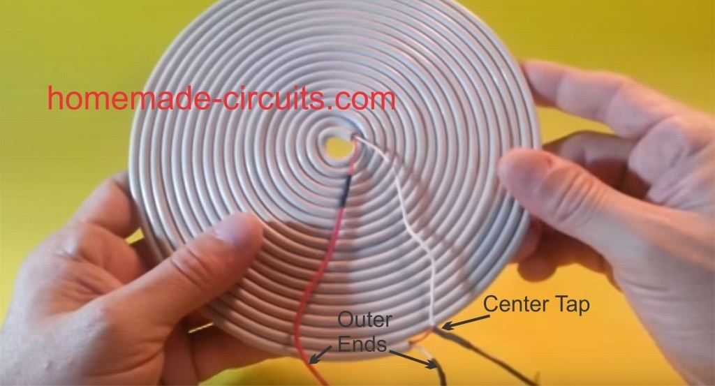
The transmitter circuit for this wireless cellphone battery charger is the crucial stage and must be built accurately, and it must be structured as per the popular Tesla's pancake coil arrangement as shown below:

Making a PCB version of the above Pancake coil.
Inspired from the above theory, the smaller layout of the same coil can be etched over a PCB as shown in the following diagram, and wired as indicated:
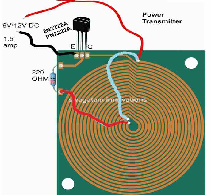
Dimensions: 10 inches by 10 inches, bigger size might enable faster charging and better current output
The figure above shows the power emitter or radiator design, also recall the circuit diagram from our previous post, the above design utilizes exactly the same circuit layout, although here we do it through a PCB by etching the winding layout over it.
A careful observation shows that the above layout has a pair of parallel coiled copper tracks running spirally, and forming the two halves of the transmitter coil, wherein the center tap is acquired with the aid of the linked red jumper wire across the ends of the coils.
The layout allows the design to be compact and effective for the required operations.
The track layout could be in the form of a square, or oval on one side and squarish on the other in order to make the unit even sleeker.
Rest of the portion is quite straightforward and is as per our earlier diagram, where the transistor is 2N2222 included for inducing the required high frequency oscillations and propagation.
The circuit is operated from a 12V/1.5 amp source, and the number of turns (coils) may selected approximately in accordance with the supply voltage value, that is around 15 to 20 turns for each halves of the transmitter coil. Higher turns will result in lower current and boosted voltage radiations and vice versa
When switched ON, the circuit may be expected to generate a strong magnetic flux around the coiled tracked, equivalent to the input power.
Now the radiated power needs to be absorbed using an identical circuit for executing the wireless power transfer and the intended cell phone charging.
For this we need a power collector or receiver circuit for collecting the radiated power, this may be devised as explained in the following section:
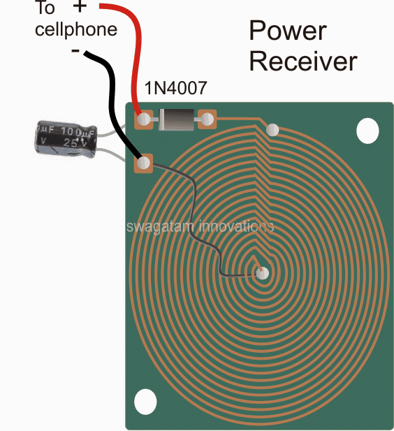
Dimension: 3 inches by 3 inches or as per the accommodation space available inside your cellphone
As may be witnessed in the above receiver design, an identical layout of the coil may seen, except that here the two concentric spirals are connected in parallel to add current in contrast to the transmitter layout which incorporated a series connection owing to the center tap restriction for the design.
The design is supposed to be small enough to fit inside a standard cellphone, just below the hind cover, and the output which is terminated through a diode may be connected either with the battery directly or across the charging socket pins (internally).
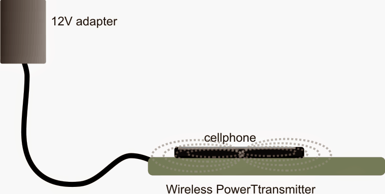
Once the above mobile battery charger circuits are built, the transmitter circuit may be connected with the indicated DC input, and the receiver module placed right over the transmitter board, at the center.
An LED with a 1k resistor could be included at the output of the receiver circuit in order to get a instant indication of the wireless power conduction process.
After the operation is confirmed, the output from the receiver may be connected to the socket of the cell phone for checking the response of the wireless charging effect.
However before this you may want to confirm the output to the cellphone from the wireless receiver module...it should be around 5 to 6V, if it's more, the black wire could be simply shifted and soldered a few coils towards the top until the right voltage is achieved.
Once all the confirmation are complete the module could be accommodated inside a cellphone and the connections done appropriately.
Finally, hopefully if everything is done correctly the assembly might allow you to keep the cellphone directly over the transmitter set up and enable the proposed wireless cellphone charging to happen successfully.
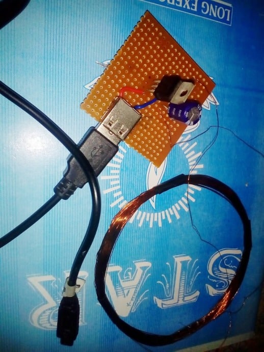
Making a Practical Prototype
The above wireless power transfer concept was successfully tried and tested with some modifications, by Mr. Narottam Gupta who is an an avid follower of this blog.
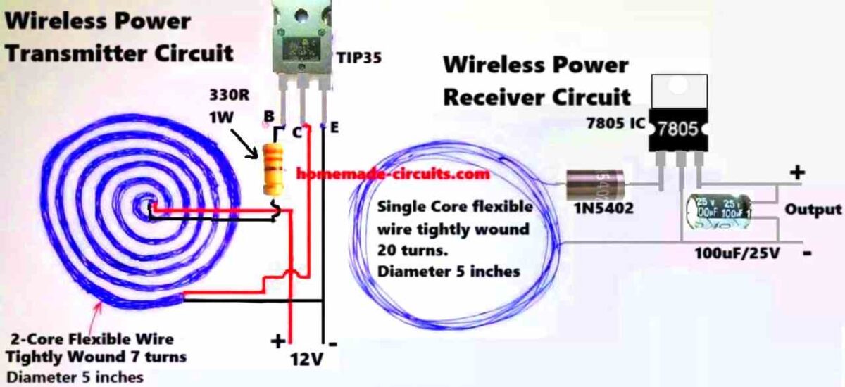
The modified wireless cellphone charger circuit diagram and the prototype images can be witnessed below:
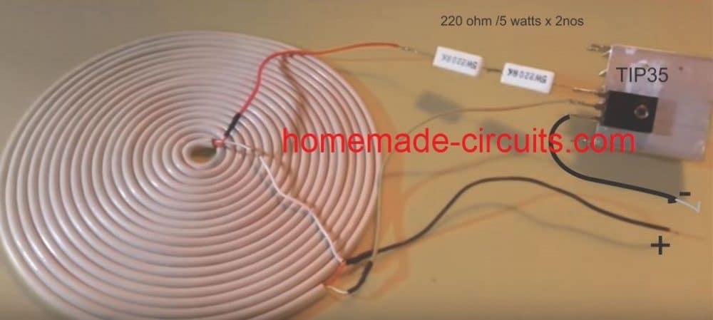
Detailed Working Description
We have got the transmitter coil which is designed as a center-tapped transformer. What this means is that there is a center tap that connects to the positive supply voltage which is at +12V. The two ends of the coil are then alternately switched to ground through the TIP35 transistor while we are running the circuit.
Transistor Switching
Now here is where it gets interesting with the TIP35. We have set it up as a self-oscillating transistor. This whole setup relies on feedback from one side of the coil back to the base of the transistor to keep those oscillations going strong. To get things started we have got a 330 Ω resistor connected to the base of the TIP35. This little guy provides the initial biasing needed to turn the transistor on just for a moment.
Induced Feedback
When current starts flowing through one half of our coil it creates a magnetic field in the transformer core. This magnetic field then induces a voltage in the other half of the coil which gives us that all-important feedback signal back to the TIP35's base. What is cool is that this feedback signal alternates in polarity which makes the transistor switch on and off.
Oscillation Formation
Thanks to this alternating feedback polarity our transistor keeps turning on and off repeatedly. This action creates oscillations in the coil and these oscillations generate an alternating magnetic field in our transmitter coil. This is what we use to wirelessly transfer power.
Role of the Center Tap
Now let us talk about that center tap again. It splits our transformer into two halves allowing the transistor to alternate current flow between them. This back-and-forth current flow is what actually generates those oscillations we have been talking about.
Main Features of the Oscillation
Finally let us touch on some key features of our oscillation. The frequency at which these oscillations occur is mainly determined by two things: the inductance of our coil and any stray capacitance present in the circuit. Since we are not using an explicit capacitor here we end up relying on:
The stray capacitance that exists between the coil windings.
The parasitic capacitance from the TIP35 transistor itself.
Prototype Description
We built this coil out of a flexible 2-core wire that is wound around 7 times and has a diameter of around 5 inches. This coil acts as the inductive element (L) in our LC circuit and its primary function is to generate an oscillating magnetic field at a specified frequency.
Next we have a 330-ohm resistor which restricts the base current flowing to the TIP35 transistor and also provides the necessary biasing conditions for it to function effectively.
The TIP35 is an NPN power transistor that can function as both a high-current switch and an oscillator. It is critical since it boosts the current required to drive that coil adequately.
The power supply outputs 12 volts of direct current which supplies the required input voltage to keep things working properly.
This is how the whole thing works. The circuit is a self-oscillating feedback loop. When we turn it on, the current flows into the TIP35's base via the 330 ohm resistor. A resonant LC circuit is made up of the coil, its inductance, and some parasitic or stray capacitance. The oscillation frequency is determined by the following formula:
f = 1 / (2 * π * √(L * C))where L is the inductance of the coil and C is that stray capacitance.
This resonant LC circuit produces oscillations at its natural frequency. The magnetic field formed by the current running through the coil produces an oscillating voltage which is supplied back to the TIP35's base to keep the oscillations continuing strong.
The TIP35 turns on and off fast sending high-frequency current through the coil. This action creates a strong oscillating magnetic field around the coil.
This pulsing magnetic field induces a voltage in a surrounding receiver coil using Faraday's law of electromagnetic induction. Essentially we are wirelessly transmitting energy from the transmitter coil to the receiver coil!
So why is this circuit oscillating? It all boils down to how the LC tank circuit (which consists of our transmitter coil and capacitance) interacts with the TIP35 transistor. The transistor amplifies the oscillations and then through our feedback loop the generated voltage in the coil reinforces the transistor's switching activity keeping those oscillations going.
The frequency at which our transmitter runs is determined by both the coil's inductance (L) and stray capacitance. If we know these numbers we can use our prior calculation to get the frequency.
Note:
It's worth noting that this circuit doesn't employ a dedicated capacitor, instead relying on stray capacitance from the coil and the wires. This can make our frequency more varied.
The TIP35 is designed to handle high power ensuring that there is enough current to create the required strong magnetic field.
If we wish to fine-tune the circuit we may do so by varying the inductance of the coil—by changing the number of turns or the spacing between them. This could help us create resonance with the receiver coil, resulting in optimal efficiency.
Formulas and Calculations
Transmitter Coil Design
Inductance (L) of the Coil:
L = (N2 * mu0 * A) / l- Where:
- N = 7 (number of turns in the transmitter coil)
- mu0 = 4 * π * 10-7 H/m (permeability of free space)
- A = π * r2 (cross-sectional area of the coil, r is the radius in meters)
- l = length of the coil (assume tightly wound with negligible height)
Diameter of Coil: 5 inches = 0.127 m
Radius: r = 0.127 / 2 = 0.0635 m
Cross-sectional area:
A = π * (0.0635)2 = 0.01267 m2Receiver Coil Design
For the receiver coil:
N = 20 (number of turns in the receiver coil)
Use the same formula for L as above with N = 20.
Resonant Frequency (f):
f = 1 / (2 * π * √(L * C))- Where:
- L is the inductance (calculated for both coils)
- C is the capacitance in the transmitter circuit (typically provided by a tuning capacitor or parasitic capacitance)
Power Output:
The receiver circuit includes a rectifier (1N5402) and a voltage regulator (7805) to step down and stabilize the output.
Power output:
P = V * IIf we Assume the output voltage is 5V (regulated by 7805) and the current depends on the load.
Efficiency of Power Transfer:
Efficiency (eta):
eta = (Pout / Pin) * 100%- Where:
- Pin is the power supplied to the transmitter circuit
- Pout is the power delivered to the load via the receiver circuit
Power Dissipation in the Resistor:
The resistor in the transmitter circuit is 330 ohms 1W.
Power dissipation:
PR = I2 * ROr:
PR = V2 / RAssuming input voltage V = 12 V:
PR = (122) / 330 = 0.436 WThe resistor rating of 1W is safe for this application.
Receiver Side Voltage:
Diode drop for 1N5402:
Each diode drop is approximately 0.7V (forward voltage).
Output after rectification:
Vrectified = VAC - 2 * VdiodeVrectified = VAC - 1.4VAfter 7805:
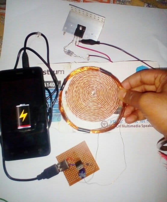
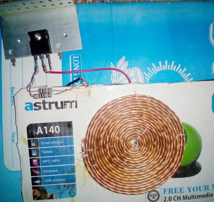
Vout = 5VTested Prototype Images
Sir I have to discuss about 24 volt induction.
Hi Swagatam, I hope you are well.
I wanted to ask you if it seems possible to make a 42V – 2A wireless charger for an electric scooter with a designer circuit.
Thanks a lot in advance
Hi Juan,
I may be possible to build it if you are able to optimize the resonance frequency of the circuit correctly.
If we can calculate the frequency and the resonance components of the circuit correctly then it will be successful.
Hi Sir. I just want to ask how do you trigger the coil? I didn’t understand the working principle. Why didn’t you switch the Tx coil?
Hi Halil, the coil is triggered and oscillated by the transistor through a feedback mechanism.
I am a student, what you did is almost the same as what I did. My project is about a table that charges a laptop wirelessly.
Can you do a simulation for my project like what you did on this page? Because I don’t know how to do a simulation.
Sorry, I am also not good with simulations, so it might not be possible for me, by the way I cannot see any simulation done in the above article…
Hello.I want to design the pcb file of this circuit..but I need calculations for board thickness.track thickness.distance between tracks and number of coils..please guide me Wireless Cellphone Battery Charger Circuit
Hi, Sorry, I do not have the exact dimensions of the board, it was designed as per my imaginations and assumptions. You will have to consult a professional PCB designer for getting the exact size and thickness. Track thickness can be 1.5 mm.
Sir on the top there you said in the transmitter coil(Rx) more turns result in higher voltage lower current while less turns result in lower voltage higher current right please correct me if I’m mistaken. It may be the reason why my power bank was unable to charge my phone maybe doe to higher voltage and lower current
I meant the transmitter coil (Tx).
Hi Sadiq, yes that’s correct. However the transmitter turns must be properly calculated with regards to the input supply voltage and must not be too less. The same is true for the secondary winding.
Pls sir what’s the diameter of the reciever coil
You can use any thin enameled copper wire, for example which are used in 1 amp transformer secondary side. Can be 0.3 mm diameter
Ok sir.so how about the coil inductance calculation and the matching resonance frequency calculation
Resonance has not been applied in the above circuits.
Pls sir why’s the transmitter coil thicker than the reciever coil and how can I calculate the coil inductance for both the transmitter and receiver and also the matching resonance frequency
Hi Melvis, it is because the receiver coil has more number of turns than the transmitter so that it can absorb maximum wireless transmission from the transmitter coil. Transmitter needs less number of turns in order to match with the transmitter frequency and to enable high current output. However, the receiver coil can also have the same number of turns as the transmitter and the same wire thickness.
What other type of capacitor can i use instead of an electrolytic capacitor
Any type of capacitor can be used but the value must be higher than 100uF
Sir Tp35C is heatup, and there is no voltage in Rx.
You will need a heatsink for it, but the circuit must oscillate first, there are many good videos on Youtube, please watch them…
Sir My circuit is running , but with 12V dc adapter, due to Transistor TIP35C. When I put 2N2222 transistor for 5V dc adapter then 2N2222 transistor is melting , So what is the method in which i can operate on 5V dc Adapter.
How can you say your circuit is running? Circuit will be running if the circuit oscillating with some frequency. If your connections are correct and your coils are correctly wound then you will get the results instantly. Check your two core wire connections with the transistor, turns must be tightly stuck with each there.
Sir, as shown in the images, the turns of Tx and Rx are same but thickness and thinness of Tx and Rx is different. But you tell me that Rx turns greater than Tx.
Sir, In your computerized Image the turns of Tx of 2 Core wire are 10…But at the below a real image in which the number of tutns are 20 of white 2 core wire???
20 is better, higher the number turns the better will be the results
Sam, there are fixed rules for making this project, everything is linearly proportionate. Lower Rx turns will give lower voltage output and vice versa.
Sir, as shown in the images, the turns of Tx and Rx are but thickness and thinness of Tx and Rx different. But you tell me that Rx turns greater than Tx.
If i used same 2 core Speaker wire for Rx coil Is it right???
Can I make 2.5 inches of diameter of Rx ?… Where Diameter of My Tx coil is 5 inches.
In 2 core Speaker wire of Tx of the wire guege number is 28 Can i use 18 number for receiver coil.
please do it as shown in the images, Tx wire should be thicker, and Rx wire should be slightly thinner. Rx coil must have higher number of turns than the Tx.
Sir what type of medium will used between coils and i have speaker 2 core wire is it right
Sir what type of medium will used between coils and i have speaker 2 core wire is it right
Sam, The medium is air core….yes two core speaker wire will do
Sir thanks to reply very soon,
Sir can i use sigle copper wire for receiver coil. How many turns give into receiver coil according to single copper wire , because 2 core speaker wire not adjust at my backside of phone , i give 20 turns of 2 core speaker wire in Tx.
Hi Swagatam, I wired a Receiver as per your design. I have coil dia. of 3 inches flat on paper with 28 swg enamel wire. I used a bridge for DC with 220 mf cap. The voltage shows 15 volts pulsating. But the moment I connect the cellphone the voltage drops to 4 volts. I am using Bluehive chinese Transmitter Rating Output 5 volts 1 Amo & 9 volts 1.1 Amp. Input 5 volts 2 amps & 9 volts 1.67 amps. Please let me know how I can improve or correct the receiver.
Hi Placid, it may be due to lack of current, or inefficient current transfer in the receiver section. Please try using thicker wire for the receiver coil, or use many thin wires in parallel instead of single thick wire for the receiver coil. Try the same for the transmitter coil also.
Hi Swagatam,
Thank you very much for quick response. After I sent my request, I made another coil with 18 swg. The current improved slightly and the voltage remained same. But the cellphone discharges instead of charging though the voltage was 5 volts (slightly fluctuating) Anyway as you have suggested I will keep trying Transmitter is a commercial brand Bluehive (chinese) so I am trying to use it and can’t do anything about it..
You are welcome Placid!
Yes, I think the problem could be from the transmitter also, since you are not able to change its winding thickness, moreover 5V 1 amp is just 5 watts which may not be enough for the modern smart phones.
The current from the transmitter must be at least 2 amps.
Hello sir its me again, first i would like to thanks to you for your great work, i have i managed to make the wireless power transfer worked using 1k ohm resistor & 12V 1A adaptor. How ever my output voltage only gets about 3V with 0 cm distance from coil so my question is how much voltage needed to charge a phone and how do i fix my circuit in order to get that specific amount of voltage? Tq sir hoping to hear from you soon.
Glad you could make it Ikmal, to increase the receiver voltage you will have to increase the number of turns of the receiver coil appropriately and also ensure that the current from the transmitter is high enough to sustain the voltage while the receiver output is loaded.
Hello sir, I want to ask a question regarding my project about wireless phone charger, are the number of turns of a transmitter coil must be bigger than the number of turns of a receiver coil? and how many turns the transmitter circuit and the receiver circuit needed? I hope you can explain to me. Thank you.
Hello Muhd, both the coils can be of the same dimension and specifications.
The turn numbers are given in the above article image.
Your website is impressive. mainly the Tesla related works. Can you please share the PCB (gerber) file of the bifilar coil ?
Hell am new here just heard of this platform from my brother,but I must say what am seeing here is really nice and recommendable.thank you Mr swag for sharing and making this possible. Thank you
Glad you liked this site Boniface, I appreciate your thoughts!
Hi,
I’m beginner in this… But i made one(Transmitter) but ended up frying the 2N2222A Transistor(I think so), it got hot and kind of I think smoke was produced when connected to 5V 1.2A mobile charger…
Well, I didn’t made a receiver as my phone has wireless charging feature in-built.
Can you help me solve this riddle… It would be great if you did so…
Hi, If you built it exactly as per the shown diagram, then it should work. The transistor will burn if its pins are wrongly assigned or if the coil terminals are wrongly wired…please recheck everything and try again.
Can you make schematic diagram if possible, it would be of great help…..
Actually, how many turns is required for the coil, i only made 15 turns with speaker wire…
I used a 330ohm resistor instead of 220ohm….
i joined the first wire from the outermost layer and second wire from the innermost layer and connected it to the positive of usb. And connected Left terminal( or emmitor of transistor to negative of usb) . And connected the middle terminal (or collector) to the resistor which is then connected to the first from the innermost layer.
And then connected the left terminal(or base) of transistor to the first wire in the outermost layer of the coil…
I hope the connections are okay… Please correct me if there is any mistake…
The diagram below shows all the details very clearly:
" rel="ugc">
Your 2 core wire must have colored wires inside so that you can select the proper wires for the connections as per the above diagram.
Another similar design can be read in the following article:
https://www.homemade-circuits.com/illuminating-led-using-wireless-power/
Hi, Swagatham
Thanks for your help …. It was great from your part.
Hi it’s me again,
I tried again as the diagram but still ended up melting the transistor 2n2222a(it’s outer part got melted). And eventually the coil became an electromagnet…
Do I need a capacitor, usually a capacitor is required for resonance to happen….
Can you help me…
Hi Joshua,
the number of turns, the diameter and the compactness of the coil all are crucial for proper functioning of the circuit, check whether all theses parameters are satisfied or not. Also, try TIP35 instead which is a 25 amp transistor and might be impossible to burn with a cell phone charger unless the pins are wrongly connected.
The diameter of the transmitter coil is around 16 cm.
A resonance capacitor might improve the results, but it will need to be fixed with some trial and error.
Hi, can you tell me one more thing… What kind of wire is used to make the coil to get exactly 16cm diameter with only just 20 turns…
Hi, 16 cm is not a critical value, it may be 16, 17 or 18, depending on the diameter and the insulation thickness of the wire, just make sure it is not less than 20 turns and is tightly wound as shown in the image.
Can i use mine without a voltage regulator
Yes you can try it, but if the cellphone does not charged then you may have to use a voltage regulator.
And one more thing I thought of using 1mF capacitor which is 63v , would that be okay with this circuit…
where did you use the capacitor? if it’s for resonance then you may have to calculate it correctly otherwise it may reduce the efficiency of the circuit
Thank you for such a great Information…….
i wont do this project but dose it realy work,(i wanna know if it realy works cause i tried it with a wireless electricity circuit and it didint work so ended up having to use a one transister circuit).
It definitely works, it has been already built and tried successfully by one of the readers
ok thanks
Will the range be increased when we increase number of turns of coil?
coil turns, supply voltage and current all these will need to be optimized to increase the range… to a certain extent
Hey.What is the range of the circuit.Thank you for your genius projects
Thank you David, the range is not above a couple of inches.
What is the size of the coil? Thank you in advance
Sir what is the use of Tesla coil since i have made the transmitter and receiver coil as that of the receiver coil in the practical version shown by mr narottam. I have connected the receiver ends directly to led and phone in parralel but only led glows and as soon i connect to phone led turns off.Therefore does adding a capacitor in parallel to inductor and then setting to resonant frequency would increase the voltage in receiver than the initial voltage i produced.I am using a turbo charger moto g5 s plus.Thanks in advance and sorry for such a long comment.
Hi Pra, yes definitely, the resonance is the key factor in all wireless power transfer concepts, without this your system will not work with the required efficiency level. Therefore fixing maximum resonance is very crucial to get optimal results. The other factor is determining the wire turns and thickness as per the load specs, for low voltage high current load such as cellphone, the coils must have lower number of turns, lower operating voltage and higher current supply.
Here the Tesla coil’s special configuration allows the use of a single transistor for forcing the oscillations in it, and it allows the Tx to become flat and sleek.
Thanks for such a swift delivery of the solution.Sir correct me of i am wrong,from my understanding it is the voltage in the secondary coil that determines the current to charge the battery.But in mutual induction if i increase the voltage in secondary coil the current would become less and vice versa.Therefore my question is that, mutual inductance should be increased or decreased ,or say it that way should i increase the no of turns in secondary coil or decrease?Thanks and please bear with me since i am a novice school boy curious to know everything.
since the above concept is a kind of transformer, mutual induction is the only way to transfer power here. In any transformer mutual induction can be improved by using improving the core efficiency and winding methods, since here there’s no core therefore there’s no way to enhance mutual induction, that is why we have to introduce the resonance concept so that the two winding are able to latch-in for genearting maximum efficiency.
The main thing that needs to be tweaked is the Tx coil and frequency matching, once this is achieved the secondary Rx coil can be experimented and optimized with much ease, by trying different number of turns and distances from the Tx coil
Thanks sir for your advice.I understood that resonance frequency is the best possible option for maximum efficiency.To match resonance frequency of Rx by Tx there are two option first of by trying different no of Tx coil turns and second the variable volatge supply.For the first one i am not sure how to change the no of turns again and again but for variable voltage should i use the variable voltage regulator just like LM317T. Thanks in advance sir you are a true help to me.☺?
I am glad you are understanding Pra, yes you can use LM317 variable voltage and begin testing with the lowest voltage may be 3V and gradually increase the voltage until you find sweet spot where the self oscillating frequency strikes the resonance point of the LC tank, or as long as the transistor temperature does not cross the tolerable limits. Make sure to use a BIG heatsink for the LM317
Sir , i went through all the comment and found that maximum are facing the problem due to heating of the transistor …. So i want to ask u that if i take all the components with the the same specs ….what should be maximum input voltage and current in the transmitter to protect 2N2222 transistor from getting hot ….plz reply sir and thankyou for sharing this beautiful idea
Prasoon, people are having trouble because they are using mismatched figures, the transistor will heat up if the circuit does not oscillate optimally at the resonant frequency, and this can be reached only when the voltage and the number of turns are perfectly matched, which will in turn ensure the correct resonant frequency. since these parameters are not critical, it can be achieved with some understanding, patience and skill, by tweaking the coil diameter, number of turns, and the voltage level…..
the easiest way is to start with the lowest (3V) application, and slowly increase it to the maximum until the right resonance is struck, having said this one must remember that the Tranmitter (Tx) coil is the crucial element here which must be built accurately otherwise the system will simply not work, causing heating up of the BJT and damage.
…The coil diameter can be roughly estimated from this figure
" rel="ugc">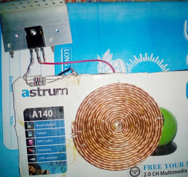
Sir, if I placed the LED in the power transmitter, will it indicate that the cellphone is charging or not?
Jomar, it can be perhaps done by adding a calculated resistor in series with the Tx power supply, and adding an LED in parallel with this resistor….when the mobile is connected, the current will increase which in turn will give rise to a potential difference across this resistor illuminating the LED.
Hi,
I have connected everything as per the diagram with a TIP122 transistor and 330ohm resistor with speaker wire pancake coil. But the problem is that I couldn’t even light up an led in secondary coil. Also I have connected an led on the power supply of the transmitter but it is blinking every second what’s the reason for all that?please reply soon……Thanks in advance..
Hi, your system must oscillate, and oscillate at the resonant frequency, only then you will be able to get the results correctly….it will be difficult for me to troubleshoot your circuit because I cannot judge what you might have missed in your design.
you can refer to the comments above for getting more info regarding the concept and the circuit…or you can try watching some related youtube videos for the same…
…alternatively you can try the following circuit
https://www.homemade-circuits.com/2017/01/high-current-wireless-battery-charger.html
Hi,
These are my components please find what is missing
For tx,
One 330ohm resistor
One TIP122 transistor
Speaker wire pancake coil(30 turns)
For RX,
One 100 micro farad capacitor
One 1n4007 diode
Coil made of speaker wire(10 turns)
Your parts may be right but they should be correctly configured and especially the coil, which is very crucial, a slight mistake in the col configuration will stop the circuit from working….
In the original diagram a Darlington transistor was not used so you can replace the TIP122 with any ordinary 1 amp BJt such as a 2N2222 or even 2N3055 will do…try this…and begin adjusting the voltage from 3V and gradually increase it until hopefully you are able to touch the resonance level.
Hi,
I have connected every thing and I powered it and I could detect high magnetic field with EMF detector will it mean that my tx is working properly….. 🙂 🙂
yes then it could be working, you can test it by keep another coil right on the Tx coil, and connect an LED across the ends with a 100 ohm series resistor…if it illuminates then you can be sure it’s working
Hi,
I have connected set of led to the secondary coil and it just blinked slightly. Then no sign what will be the reason??
that means your Tx is not working, what power supply have you used for the Tx?
I have provided 5v 2A power supply
check with a frequency meter whether your circuit is generating frequency or not!. or try increasing the voltage slightly and check the response!
Hi,
I have changed the led to 1watt led and added a resonant capacitor to it when I keep it above the tx and power on, when I shake the circuit it blinks
Is it necessary to use the same wire as secondary coil that is used in tx coil?
Any way thank you very much for your guidance ….:)
Please reply soon……
So it seems now you are able to light up the LED on Rx, right?
if you have added a resonant cap then try to further adjust its value until you can get the maximum efficiency and maximum brightness on the LED from maximum possible distance.
same wire spec is absolutely not necessary, the wire thickness is related to current of the load, however the Rx coil turn nos should preferably match with the Tx.
you are welcome!
Thank You very much….
Iam using mobile phone adapter of 5v 2A . Is it OK? I will provide a link later after I upload a video on this project on youtube, If you can solve the problem it will be very helpful for me………
I think the power supply should be a variable type so that you are able to vary the voltage and adjust it for getting the best possible outcome….sure, I’ll be glad to see the video.
Is there a relationship between the distance between the coil and the current of the circuit?
Not with the distance, rather with the load current…
Hi,
I have changed the circuit and added 555timer and FET MOSFET with resonant capacitor as I couldn’t light up an led in the given diagram that is with a single transistor , I think that when I connect the two terminals then the supply is shorted so when I shake it it blinks for a second then cutoff. Iam giving you a link so that you could check the diagram I followed…… I will put the video tomorrow…..
you can send the link but a video may not help me to troubleshoot the problem, you will have to do it yourself, if you do it with proper understanding of the concept then definitely you will be able to achieve success, many people have already built this successfully.
Thank u and I will try my best to get it done …….
OK great, wish you all the best!
thank you sir
if the distance of the two coils is exactly 1 inch, will the output power of the source change?
yes definitely, the distance is inversely proportional to power output from the receiver coil….
Sir,
I made a pancake coil with 30turns out of a normal speaker wire. Can I proceed with placing a TIP transistor , diodes and capacitors as shown in the diagram.
Please reply soon, its for my ‘wireless charger for Mobile phone’ project for my Science exhibition.
Navneeth, make sure the coil is designed as given in the following diagram:
" rel="nofollow ugc">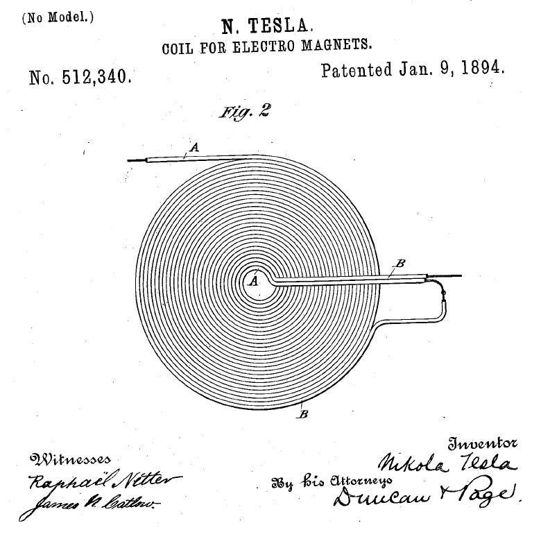
after that begin with a lower voltage and gradually increase the voltage until you hit the correct resonance
Sir,
I have made the same(pancake coil)but as it is speaker wire on is on the top of other.It is about 5inch in diameter . I even connected my
MPS2222A transistor properly but after I gave supply of 9v and 5v , transistor is really cool not at all warm. Can you say what is the problem
Thanks for the previous reply.
Also, can you please tell which component in the transmitter coil convert DC to high frequency AC . Thanks in advance…
Navneeth, the wires must stick together tightly, otherwise it will not work, and make sure the ends of the wires are terminated exactly as indicated in the various diagrams or else the circuit will not oscillate.
sir,
I have stick it tightly, with super glue and ends of the wires have been terminated as per the diagram.
sir which converts DC TO AC? please tell….
and is my transistor npn or pnp
please suggest a solution it is for my science exhibition…………
The coil and the transistor convert DC supply into a high frequency pulsating DC….the transistor should be a NPN.
you can also take the help of the following article for understanding the concept better
https://www.homemade-circuits.com/2016/02/illuminating-led-using-wireless-power.html
Hi Sir
If I am increasing the number of turns of the sender coil than should I also have to increase the receivers coil.
And also if I am increasing no. Of turns of sender coif than should I have to increase the battery source.
Can I use a Normal Samsung Data cable charger .
I am using 2N2222 transister will it be able to hold the charge produced by a mobile phone charger.
SIR PLEASE REPLY AS EARLY AS POSSIBLE
THANKYOU SOO MUCH
Hi Parth, the transmitter coil and receiver have no direct connection. The receiver coil parameters can be increased for optimizing more current and voltage.
whereas the transmitter coil parameters may need to be optimized for better resonance so that maximum current can be transfered to the receiver coil.
therefore both are independent of each other and they may be tweaked for achieving different specifications.
however exchanging optimal current across th etwo cols is the main requirement.
remember if you change the transmitter coil turns then you may have to change the supply voltage accordingly and check the response until you get the best possible frequency and resonance for the coil
use TIP122 instead of 2N2222
hi can i use single copper wire two times instead of double copper wire you used?
yes that's possible but make sure the wires stick together with each other without gaps…
Dear Guru,
Since there is no PWM fed to drive the transistor then at what frequency a single transistor when wired to self oscillate put out?
On the receiver coil which configuration rectifier would work best?
What could be done in order to regulate the output voltage from the coil?
Thanks
Hi Sherwin, I am not sure about the frequency, you will have to measure it practically and the results may depend on the coil and the resistor values.
on the receiver side you can use the following concept which will regulate and rectify both together
https://www.homemade-circuits.com/2012/08/simplest-dc-cell-phone-charger-circuit.html
Sir,can u explain how this circuit works like what is the importance of each component used,why it is used..???
DP, the working principle is similar to a blocking oscillator or a joule thief circuit
https://en.wikipedia.org/wiki/Blocking_oscillator
The resistor is used for limiting base current to the transistor and for ensuring optimum current in the coil without damaging the transistor.
Thank you sir…it was really helpful ..
you are welcome!
Sir,I did this project and got the output.I just need to give a presentation on it by tomorrow wherein i will be questioned about how exactly every component is used.U asked me to watch for blocking oscillator but i cudnt relate it to this ckt.Can u please give me a detailed info about how exactly every component from both transmitter and receiver is used. It will save me from the presentation tomorrow.
DP, that's great and congrats to you.
The design of the above wireless transmitter circuit is exactly of a blocking oscillator, you can compare the diagram shown in the following article with the above concept and you will find them to be exactly similar:
https://www.homemade-circuits.com/2017/04/blocking-oscillator-circuit-how-it-works.html
a comprehensive explanation of the circuit functioning is provided in the above linked article, however it looks much too elaborate and complex for any newcomer
secondary coil counts in micro volts ? What could be the reason for that?
your circuit is not correctly optiized
thanks! what if i use a pvc covered 2core wire as a substitute for magnet coils? will it affect the voltage?
It will work if the insulation is not thick and the coils are tightly wound
Thank you!! :)) my transmitter has 18turns tightly packed but not more than 4inch in diameter, but here my 2n222A transistors keep on smoking, and gets very hot! Help me
begin by applying 3V and then slowly increasing until the point where the transistor begins getting hot.
make sure the circuit is oscillating through a frequency meter.
alternatively you can try adding more turns until the transistor stops heating up.
Sir I got doubt that u said that current enters center tap coil through one half winding say winding 1 reaches base which triggers transistor means on which shorts collecter and emiiter current flows collector to emitter to gnd through other half winding say winding 2. how can base current removed from which half winding to turn off transistor
Sampath, please see the following diagram
2.bp.blogspot.com/-vQCLvBuzLA0/VgfX-4fHoDI/AAAAAAAALZ8/OKNJAWS5eMw/s1600/wireless%2Bpower%2Btransfer.png
as soon as the transistor triggers the 3V is sucked in by the transistor collector which inhibits the 3V towards the transistor base.
How can I add capacitor to center tap coils
for the above design don't add to the transmitter…add only to the receiver coil, and keep tweaking value until you find the highest achievable voltage output from the Rx….
sir,
can you tell me the voltage and current wave forms through the coils?
also why a center tapped coil instead of a normal one?
thank u
Lochana, the waveform can be confirmed only through an oscilloscope, most probably it should be a distorted square wave or sawtooth type.
without center tap this oscillator will simply fail to oscillate, because one of the winding of the coil helps to maintain the required feedback for sustaining the oscillations.
I'm trying to build wirless mobile charger using the following circuit but I can't figure the no of turn of the transmission and receiver coil can u please find it for me.can i have your email coz i can't attach the photo into this comment
Please reply ASAP
Thank u
you can try the following concept
https://www.homemade-circuits.com/2016/02/illuminating-led-using-wireless-power.html
you can further tweak the number of turns and voltage specs to optimize the results and improve it even more
Dear sir Swagatam, I am really interested in this post. Would u like to send me the newest diagram circuit and detailed information please. I would appreciated it. Thanks
Hi Kaze, will try to present it soon in this website….
is capacitors connected parallel to the inductor coil sir
yes, that's right
Sir in data sheet there are two HFE values which one can I choose sir
take the average of the two….
Sir is it possible greater output I used tip35c transistor in the place of 2n2222a transistor in the above circuit
And I used 2 220ohms base resistors can I reduce the base resistor for greater output sir reply me
Sampath, greater output can be achieved by matching resonance between the Tx and Rx, which can be done by adding capacitors across the coils. Using higher power is a secondary option which can be tried after fixing the resonance.
I'll soon publish a detailed article explaining this.
Sir I understood that base resistors r used to limit the base current of the the transistor sir how did u calculate the resistor value 220ohms for 2n2222a transistor , I used tip35c with two 220ohms resistors in series at the base as shown in the video can u show me the calculations sir reply me quickly sir
Sampath, it was not calculated, it was referred from other online examples….although it can be calculated using the following formula.
R = (Us – 0.6)Hfe/Load Current,
Where R = base resistor of the transistor,
Us = Source or the trigger voltage to the base resistor,
Hfe = Forward current gain of the transistor,
Sir 2n2222 transistor or bc 548 use and what is copper wire gauge and coil size in cm.
use 2N2222 with 6V supply, and please refer to the diagrams and the comments, and experiment with the coils accordingly….
sorry sir iam asking about the operation of resistor which is connected at the base is by connecting the resistors at the base more current is drawn at the base of transister, sir tell me that what is the use for by connecting the resistors at the base can u reply me fast sir
If you don't connect the resistor, the transistor will become hot and blow of….
how many distance power can be received by transimitter.
Sir can u plz tell me the use of resistors at base
it's 220 ohms
How many turns of transmitting or receiving coil
Sampath
Sir
U made the above circuit is u used PVC or super enamel copper wire if u used PVC then what no. Of cu.Guage wire I should use or if use super enameled cu wire then tell me the guage no. I m making new one
2.whats the use of resistors at the base why
Sampath, It was PVC wire, but I don't remember the dimensions, you can refer to the following similar idea and build according to this
https://www.homemade-circuits.com/2016/02/illuminating-led-using-wireless-power.html
Sampath
Sir I'm saying that I used 30 guage wire for transmitter and same for receiver also I saying that I want to use 18 guage wire for transmitter for greater output ,replacing 30 guage wire with 18 guage wire is it possible high output with which wire
use 3 or 4 numbers of 30 SWG wire in parallel (together) and wind the coils, and check out the response…
a single 18 SWG will not be efficient…
I hope you understood what I am trying to suggest??
but anyway you can try a single 18 swg also, it's your wish
Sampath
Sir how much guage wire u used in above circuit you made I made it with 30 guage copper wire but it not geting Better current output it getting output very less is it possible with 18 guage wire for greater output in the above circuit
you can try winding 3 or 4 numbers of 30 SWG wire in parallel, and check out the response…
a single 18 SWG will not be efficient…
Sampath
1.Sir i want to know the transistor internal operations how currents going through switching of base collector emitter plz help me this out how it is converting Dc to ac in the above CkT
2.Plz tell me is it possible with 18 guage copper for greater output in the circuit u have shown above
Current enters the center tap of the coil and reaches the base of the transistor through one of half winding of the coil.
This triggers the transistor which instantly shorts the center tap current to ground through the other half winding, which removes the current from its base.
This forces the transistor to switch OFF, reverting the circuit to its initial position and the process repeats itself causing a rapid push pull oscillation on the coil….
Sampath
1.Sir i want to know the transistor internal operations how currents going through switching of base collector emitter plz help me this out how it is converting Dc to ac in the above CkT
2.Plz tell me is it possible with 18 guage copper for greater output in the circuit u have shown above
Sampath
Plz tell me is it possible with 18 guage copper for greater output in the circuit u have shown above
The process is exactly similar to our transformer concept, the only difference being the coil distances which are completely isolated in wireless transfer concept, whereas in transformers the cols are wound one over the other.
Sampath
If u don't mine Sir can u explain the concept clearly in detail please I have made the circuit can u explain me how the currents and fields flow in the coils in detail please
Sir can u explain the concept clearly
Hi master see you again,
can U help me make 3 coil charger circuit with input 12V/2Amp & Output 5V/2Amp or 5V/1Amp ?
thanks (^_^)
Iqbal, how do you want to connect the coils? One above the other, or separately for different receivers?
To use it separately you may have to use separate circuits for each of the coils.
Master can I join 3 coil in 1 circuit ?
thanks before
3 coils in one circuit?? sorry I could not understand your point, did you mean 3 parallel wires inside the bifilar coil??
connecting 3 separate coils from a single transistor oscillator will not work…
i mean using this coil
cdn.lairdtech.com/home/brandworld/files/SWC10056AA120-500.jpg
you can connect them in parallel one on top of the other, but that will also require the resistor to be appropriately calculated, as the inductance would change.
master can I using head cable as coil in transmitter?
Iqbal, if it is configured in the bifilar style as explained in the above article then it will work
ok master Thank you very much !!!
hi Can all components are stored in the transmitter?,
so that the receiver is very minimalist, and
how it can function long distances?.
please send me an email to the schematic drawings in:
8ball.ajjah@gmail.com
thanks a lot before
yes, it can be done by using SMD components
long distance is not possible.
Master, can you make the scheme 5V input transmitter and receiver outputs 5V 2A with SMD components for me?
sorry I'm a newbie and want to learn
please send me scheme picture to 8ball.ajjah@gmail.com
Thanks a Lot
Iqbal, it won't be possible due to lack of time, the concept has been discussed elaborately above which you can go through and design it yourself through some trial and error.
Ok Thank a lot Master ! (^_^)
Hi,
I want to make shake powered rechargeable small flashlight with low budget, can u help me with a circuit,
the charge will last to light one led for 30 seconds
Regards
Dennis Bosco Demello
Email Id – dennisdemello8@gmail.com
Hi, I'll try to publish it soon….thanks
Pls tell me, what kind of wire you use in transmitter coil
Dear sir,
i had test you circuit it is working well. i didn't use 7805. i check with LED. it is glowing.
now i want to ask you, can we use 5volt mobile charger instead of 12volt 1.5A charger? it will help to remove 7805.
Ninad, a cellphone charger could be much weaker with its current and voltage so the LED would also illuminate dimly….the receiver output will be directly proportional to the transmitter output which in turn will depend on the power of the supply used
Hello sir,
is it necessary to connect capacitor and diode in receiver circuit. I am connecting only led with two coils of copper wire in receiver section and it's not glowing.
Please help me…
Thank you
Chaman, you can try the following circuit
https://www.homemade-circuits.com/2016/02/illuminating-led-using-wireless-power.html
Hello sir iam adnan. iam also working of wirless power transfer. i made a project in which i have charge a mobile but now iam want to increase its effeciency so that it will able to charge a laptop and i used tesla bifilar coil for transmitting with a radius of one feet and unifolar recieving coil of nearly 8 inches power recieve will be aproximately 8wat. can i increase this power level by using multiple coils on recieving side or any other advise so you give me to achieve my goal. kindly reply i will wait for your suggestion
Hello Adi, the transmitter and the receiver coils should be designed to resonate at optimal levels, that's the key to make the most efficient and powerful wireless transfer.
The concept explained in the following link is similar to wireless power transfer and you can replicate the concept for your specific application….however the wire gauge must be correctly calculated as per the current demand of the system.
https://www.homemade-circuits.com/2016/09/designing-induction-heater-circuit.html
Sir, I got small voltage in the receiver, How to make it 5v? What I did is I made a total of 30 turns in tx and the same in rx. Thank you very much!
Ronnel, move the Tx coil it closer to the Tx coil and see if the voltage in increasing or not….if not then your assumption regarding the wireless transfer might not be correct…first confirm this then we can move ahead.
Sir,
How to increase efficency of this charger?and is it works for all cell phones?
shivam, you can go through the following article for all the detail
https://www.homemade-circuits.com/2016/09/designing-induction-heater-circuit.html
yes it's for all mobiles
Sir, what type of wire did you use in your receiver?
it was 2-core flexible wire in bifilar mode.
Hi sir just to check if it can be done using normal copper wire instead of the 2 core type.
Best Regards
Normally copper wire will work but you will have to configure it in the bifilar mode, exactly as the dual core wire is done…
Thank you for answering Sir. You are a great help. Have a good day
you are welcome!
Sir, thank you for answering. i now have a clearer concept. i will tighten wind the turns later.
I am currently using TIP35C. I am using 470 ohm resistor and have 18 turns. Will that be enough for the circuit to work? Thank you so much. have a great day.
Best regards.
Thanks Allen, you will have to confirm it by practically testing the setup or by solving formulas, it cannot be judged by guessing..
Sir, I was able to light a LED using the modified circuit however, the TIP35C gets really hot. Can you share substitutes for the TIP35C that can bear the electrical flow? by the way, my aim is still to charge the phone. I hope you can give me answers and it will be much appreciated.
Best regards.
Allen, TIP35 is not the problem, in-fact TIP35 is an overkill, your circuit should work even with a TIP31 transistor.
make sure the coil turns are tightly wound without gaps within the turns, and try increasing the number of turns with respect to the center tap, and see if that cools the transistor.
sir iam using 30swg for transmitter and receiver for tx 18 turns two core flat spiral coil and for rx nearly 60 turns like wound coil is there any method to reduce the adopter heating by changing the windng turns or other
Sampath, you can use a 555 IC oscillator and tune the frequency and the inductance of the coil to generate optimal resonance, this will allow max efficiency for the circuit and minimum heat from the adapter.
you can use this software for calculating the resonance frequency
https://www.homemade-circuits.com/p/resonant-frequency-calculator.html
for a 555 IC a center tap coil cannot be used….a two wire coil will be required
sir is there any alternative without using other adopter is there any other reason for adopter heating sir give me formulas and theoretical derivation sir in pdf any link
Hello again sir, what is the size of the 2 core copper wire that you used? I'll be waiting sir. Thank you☺
Allen, from the image you can approximately judge the dimension of the coils with regards to the other materials lying around
Sir, i appreciated you noticing my question. Another question sir, in your 1N4007 rectifier diode, what is the specific voltage of that rectifier? Your answer is very much appreciated. Have a good day ☺
thank you Allen, A 1N4007 is rated to handle around 1000V and 1 amp current
Thank you for the answer, Sir ? . I like your set up?
sir im getting output at a distance of 2 inches i used 12v 1.5A adopter and tip 35c transistor and coil which is shown on the video u posted above but when i connect mobile phone its just chrgng for 2min then after adopter getting hot and stops working i think supply will be less can i use 12v 4A for tip35c transistor
yes you can try a 4 amp adapter and check the response.
Hi Allen, the leads are obviously connected with the (+)(-) terminals of the coil output (after the diode), it is not visible because it's shown as being inserted from the other side of the board.
For details please refer to the images which are posted at the end of the post, the one which is drawn with pen.
what should be the number of turns in the transmitter coil as well as the receiver coil? and what is the SWG of both the coils? Please, sir tell me as soon as possible. I making this project in college. Help me.
24 SWG can be tried initially
Sir,
is it possible to use CAT 5 wire to fabricate the coils, I have tons of it…
Vixr, if the strands are configured correctly as per the layout of the shown bifilar coil, then it will work
Hello Sir,
Thank you very much for all the useful information you spend time and knowledge to spread on your website !
I'd like to get out of the "trial and error" area, as I need to design a reliable circuit that could receive 9V at 400mA (minimum values) from a 12v power source on the emitter side. Coils diameter must be <40mm and the two coils will be distant of 1 millimeter.
I assume that there are laws and equations behind the transmitting efficiency, voltage levels, and efficient commutation frequency for the transistor, but couldn't find it yet… If you know them and don't mind sharing, it would be greatly appreciated 🙂
Best regards, Julien
Hello Julien,
The most efficient response can be detected and found only through a practical trial and error method….because formulas can have issues due to incorrect selection of the parameters, but a practical approach will always be precise.
The efficiency will hit the max when the two coils oscillate at their resonant frequency…the resonant point must lock across the coils, that's the critical thing we have too consider while optimizing the two.
Instead of the transistor/inductor "blocking" type of oscillator you can try other forms of oscillators using IC 555, IC 4060, or through half-bridge driver ICs which will allow you to investigate wider ranges….
Hello Swagatam,
Thank you again for your detailed answer. I perfectly understand that real tests are the most efficient way to get reliable results, but I would have liked to save time, by approaching the optimized config with calculations…
Thank you for pointing out other methods, I'll have a look further if I can't make it with the blocking oscillator principle…
I may come back to you soon if I find something interesting 🙂
Have a good day,
Best regards, Julien
You are welcome Julien!
sir thanks for your quick response, i have another question. What transistor can i use instead of tip35c? i want a transistor which can hold more heat. im using a 12v 2amp adapter. I had an output of 5V and 1 amp and a coil distance of almost 1 1/2 inch.
You can use TIP3055 or 2N3055 instead.
i would like to know how can i parallel my transmitter coil? i want to add more turns so instead of making another one from scratch i want to create a coil and then add it to the one im using. thank you very much. 🙂
No that will not work…you will have to use a single coil for the intended performance
Sir I made the revised one with the TIP35C and we got an ouput of 5.4 V and 1.4 amp in the receiver end and the phone is charging but the problem is the transitor is getting very hot to the point that it emits smoke. We tried heat sink and it failed. Our source is 12V 2 amp. Thank you !
Carmelita, the transistor will become hot if the inductor and the transistor does not oscillate at an efficient rate, which might lead to the consumption of excess current by the transistor.
Try increasing the number of turns of the transmitter coil or try reducing the voltage until the transistor operates at a cooler temperature
Thank you sir. I will update if it works.
Its me again sir, does the amount of input voltage affect the temperature of the transistor?
Tried 3V 2amp source transistor is still very hot
try the configuration as explained in the following article:
https://www.homemade-circuits.com/2016/02/illuminating-led-using-wireless-power.html
My 2n2222a keeps burning out, and I have to replace it every time .
What do I do about that, if I'm to reduce the power or voltage, how do I do it .
PS, my power source is usually my laptops USB port
pancake configuration is not compulsory, it just needs to be in the form of a coil….
if it's configured as shown in the diagram then it will work
Hello sir. Is it okey we use #18 wire for transmitter and #26 wire in receiver? How about the ideal number of turns for the coil? Do we need to compute?
hello domnic, there's no ideal number,because the coil dimension is strictly related to volatge frequency, and current…so all these needs to be perfectly optimized through some trial and error to get the maximum efficiency.
technically wire gauge must be thinner for the transmitter and thicker for the receiver
Sir,i tried to made it…evertime my transistor is burning out…sir hlp me to solve it out..contact me to sagarneel.bosu@gmail.com
Sagarneel, please go through all the comments, I am sure it will help you understand the issue and find a solution…or you can try with a lower supply voltage and try increasing it only upto the point where your transistor is not heating up.
I did everything right…but I am not at all getting any output at the reciever end..please help
If you did everything right, then it should have worked.
I have referred a video link in one of the above comments, please watch that video, it might help you troubleshoot your design.
Pardon me sir. With all due respect, how can this be a wireless charger if usb cable is still needed to be connected to the receiver?
Thanks btw for your informative thread. We need more people like you sir. Salute!
Good observation Mharlee, thanks! The shown experiment using USB wire is just a prototype which confirms two things: the wireless power transfer concept and the successful charging of a cell phone using this concept….the USB wire can be ultimately eliminated once the receiver circuit is somehow accommodated inside the cellphone back cover…once this is done, the cellphone will not require any form of wire and could be charged just by placing it over the transmitter unit.
Sir I'm a novice at this, I did everything exactly as I saw it except my coil doesn't have up to 15 turns, when I power it my 2n222a gets very hot and burns, is it because of the coil or is there anything else I can do about it ?
Michael, yes it could be because you reduced the number of turns…in that case you can try reducing the supply voltage to a lower value and check the response
Hi sir. I wanna make a wireless charging which is like yours, but I uses Galaxy S6 from Samsung and it has a NFC to it which also can be use for wireless charging. So did I still need a receiver module or I can directly put my phone on top of it? If you got the answer please send it to my email on letsmake0470@gmail.com
sorry, I do not have much idea about it!
How is NFC related to wireless charging??
most of the appliances in your house has a 2-core wire as the mains cord
Sir I made that transmitter from your above diagram of transmitter
But it is not working
Sir,
In transmitter circuit how can produced high frequency power ?
By using transistor, but for transistor switching needs a continuous pulse,here the transistor from where get that type of pulse ?
Please explain…
(Actually my teacher asked me that type of question but I can't explain properly.)
Narottam,
the working of the above design resembles to a "blocking oscillator" functioning, where the transistor is switching is blocked and released at a rapid rate resulting the generation of pulses. This happens due to the coil feedback tap.
https://en.wikipedia.org/wiki/Blocking_oscillator
Ok…thank you…#Sir…
Hi sir I have a new idea regarding this project . why we not use this circuit as a hand gulf . how future stoic it look .
Please make some comments on this idea
Hi Kuldeep,
sorry I did not understand your point…how can it be used with hand gloves?
Hello sir..
Can give me all components that's use for this project… And give the value
Sir, I would like to give you a lot of thanks for showing my projects design in your blog.
The pleasure is all mine, Narottam…
Good day sir Narottam. What 2 core copper wire did you use? And what awg of receiver did you use and how many turns did you apply? Sorry for the questions but I am currently needing your answer. Thank you and have a great day.
sir me Kuldeep Tripathi i make this circuit but i have a question related this circuit . When I supply 3 volt and 1000 milli amp so the reciving volt is 6 v please help me i want to charge my mobile of 1800 milli amp
Vaibhav, do you mean to say you are getting 6V at the receiver end? If it so then you can still use it for charging your cell phone by adding a 5 ohm resistor in series with the output.
Sir How much capacity of capacitor u have used in receiving coil.
Sir,
I made it but one problem,
I get sufficient voltage in receiver but current is not sufficient. So showing the mobile is charging but mainly it's not charging or charging too slowly.
So,plz tell me how can I increase the receiver end current ?
I used 12V, 1Amp transformer for power supply.
Narottam, try adding more number of coils parallel with your existing receiver coils, this will help to induce or absorb more current from the transmitter…also make sure the Tx transmitter is supplied with sufficient current from the power supply.
I am afraid 12v 1amp will not do….use a 15V 3amp or 5amp..
I would be interested to see the pics of your design with full details…it would help the many readers to understand the concept better,
Hello sir i made this circuit it is working good but I use 2N3904 and it get hot on few minute so please give name of a better Transistor .I also use BD139 but it not work
That's great Kuldeep, however BD139 should also work may be it's faulty or not connected correctly.
you can try the other alternatives as suggested in the previous comment…a TIP122 can also be tried
8050 can also be a good candidate.
Please suggest me any other transistor . please reply me soon . please give me many choice please.
you can use a BD139, D1351, D880, D313, SL100, TIP31 or any similar
Please can i use ceramic capacitor for the reciever circuit
And how many capacitor will I use for the reciever circuit
Ceramic capacitor will be fine but the value should be 100uF. You can use any value higher than 100uF
Can I use BC547 IN PLACE 2n2222
NO, you can use other higher rated BJTs than 2N2222, but nothing lower than this.
Hello sir I have many question regarding this post .Are you tested this circuit. I have not more knowledge but I think than induce current is only for AC current . Sir you use 12 volt 1.5 amps. Can I use an invertor battery of 12v/180amps .
Please clear me what is SWG Number of copper wire and number of turns .
Please reply soon .
Thanks in advances
Hello Kuldeep, please go through the comments, and you'll also find video link which you can refer for more info.
if you are new then I would recommend NOT to try this circuit because it can be very difficult for anybody who does not have a thorough practical and theoretical knowledge of electronics.
Pls sir I used 2N2012 it worked fine ,had a voltage of 5v at the receiver but wasn't able to charge my phone .why?
An sir pls can the distance be increased? How so?..thanks. Please reply soon
I am glad you could succeed with the project, the cell phone might not be charging because of low current, try increasing the input current and check the response….or you can also try decreasing the distance between the Rx and the Tx
sorry the distance range cannot be increased by much, that will strictly affect the performance of the output
Sir please how can i make mine to charge fast
To make the charger faster you may have to use higher amount input current through the transmitter
I've taken the time to design this on a 4×4 inch PCB in Eagle CAD if anyone's interested. Willing to share as long as the files are not altered in any way. DRC rules pass for production @ OSH Park.
Relic 1974 – I AM interested in the PCB pattern IF you can please send me a .png or .gif or .jpg graphic of it ?? theiceprince597@gmail.com – Thank you in advance Relic1974 – Huggs ! <3
Could the transmitting coil be made on transparent printer film (like the film used to transfer toner to PCB when making your own boards) and conductive ink? I was thinking of the cost of copper clad or having a 10×10 inch PCB made which would cost a lot. My idea is to use 2 sheets (legal paper size) of the transparent film and use conductive ink to draw the coil design on one sheet. Then insulate by placing another sheet over it. Use solar panel tabbing/wire to make connections with conductive glue or tape. This would also be a very thin design. Question is … could it handle the current? I'd probably have to draw the traces pretty thick and wide. Ideas ???
That's possible if sufficiently thick and wide tracks are created with the ink, because the track thickness and width will determine how much current it can handle and can be manipulated by the designer….or alternatively the receiver section can be simply implemented using a pancake kind wire assembly, as shown in the video, because the compactness of the receiver may be not so important.
hello sir, why its not work in my project. i was trust your tutor but not work. i make coil 18 turns in transmiter n power adapter 12v/1,5amp, in receiver i make coil 24 turns. but its not work 100% . pls help 'me.
I have checked it myself and it worked for me, see the video above for more info, if still you cannot make then sorry i can't help.
Please can i use a 5v 2amp charger in the input of the tx
You can try it, but if the response is not good then you may have to increase it to 9V or 12V.
Hello watched that video
Done editing but still there is no output in my secondary coil .
BTW i m using a old samsung mobile adapter as power source whose output is 5.13vdc.plzz help
Hello sir
Was trying the same on a pcb with 24 gauge copper wire ..
But transistor burnt …
Plzz help with solution
see this video:
https://www.youtube.com/watch?v=4UmVLfFNx7U
Back EMF occurs in between transistor switching, when the magnetic field of the coil collapses (which is what makes it self-oscillate). This back EMF can be a spike of high voltage depending on the coil design. I suspect this is what is burning out your transistor. Try placing a 1N4001 or 1N4007 diode between the collector and power supply. This blocks the back EMF current from re-entering the collector. You may also want to protect the emitter/base junction with a 1N4001 by wiring the striped side of the diode to the base and other side to the emitter. For an example, just look on google for any "Bedini SSG" circuit which protects the transistor in the same manner.
I don't think back EMF could be the problem, because it's a self oscillating circuit and not induced by an external agent, I have never seen a diode being used in self oscillating circuits for back EMF protection….may be because the coil turns are significantly less and the frequency is high.
the problem could be due to a wrong wiring, or wrongly connected coil, or a mismatch between number of turns and input voltage.
It's the same magnet kicker principle!
Hello again sir. I tried to constuct the circuit on breadboard but it is not working. I think theres a problem with the coil. is the number of coil turns on the transmitter the same also with that of the receiver. Sir please help me out. Thank you.
Hello chara,
you made the coils on breadboard?? please explain your prototype so that I can locate the fault.
you need to do exactly as shown in the above article, if you are not able to make the PCB layout coils, then replicate it with wire coils which should be exactly identical to the PCB configuration.
the receiver coil numbers is not crucial, more number of turns will more voltage and vice versa.
Thank ypu for the answer sir. i want to ask again if what type of copper wire(coil) was used?
you can use any super enameled copper wire or pvc flexible wire…
what swg wire is required to make coils?
any gauge wire do initially, it's related to current so won't affect the transfer operation in any manner.
Sir i want to know if this circuit is working i wAnt to make it for my project
Chara, I have tested it using flexible wire coils, but not with PCB yet, but I am sure it will work in this mode too, if optimized correctly.
sir i tried it by making different four coils every two coils joining required points but not placed like you showed but when i connect 6volts source transistor burnt.i connected all elements as you showed in picture.What can i do to perform surely?please help me.
Mohammad, I am not sure exactly how you might have connected the elements, but you can try correcting or troubleshooting the circuit by first using a 3V supply and by checking the response of the Rx at touching level..if it works then you could increase the voltage gradually until the transistor is felt warm…then you could increase the turns for reducing the warmth on the transistor and proceed so on..
hello sir, avid reader, first attempt at one of your many informative circuits. Just to clarify the main power source for the transmitter reads 12.5 volt 11.5 amp in description but in the picture it shows only 1.5 amp since the 11.5 might have an extra accidental one only because I've never heard of such a high amp DC power source sorry to bother and please never stop teaching, your ability to clarify electronic circuitry has been second to none a long overdue thank you is owed , sincerely Michael Shoop
Thanks Michael, It looks like a typo in the article, it should be 1 amp actually, or may be 2 amps….not more than that.
I'll correct the mistake soon.
Sir how much distance between transfer coil or receiver coil
not more than 1 inch
can i remove the capacitor in the power receiver?
then the output will be accompanied with ripples, it won’t be constant
TY sir. What is the short explanation in your wireless cellphone charger circuit?
jomar, all the explanation is already discussed in the content, you can select whichever portion suits your requirement
Sir what the copper coil used in transmitter and receiver