LI-FI is buzzing around the Internet since past few years; recently LI-FI is gained more popularity around the internet and developers. LI-FI stands for Light Fidelity which was coined by Harald Hass.
Circuit Objective
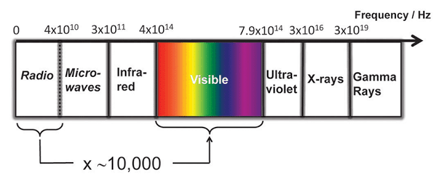
The objective of LI-FI is transfer data through visible light. Since the bandwidth of visible light is 10,000 times more than Radio waves, more data can be transferred through light at short period of time.
Visible light communication (VLC) eliminates the risk of some disease caused by the Radio waves due to long period exposure.
This protocol can be adapted where Radio waves are restricted, such as airplanes, hospitals, and in some research facilities. Researchers reached bit rate of 224 GB/s which is 100s of times faster than our average WI-FI connection at home or office.
This article explains about the basic idea how to make a very simple LI-FI circuit in which we will be able to transfer any audio source through light and receive it from the receiver which is placed few feet from the Transmitter.
Here explained about analogue communication through light, where as original LI-FI system uses digital communication, which is more complex and difficult to make one at hobby lab. But the concept is exactly the same.

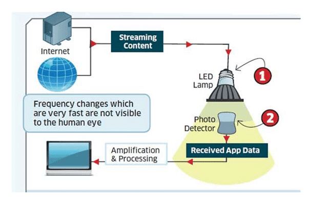
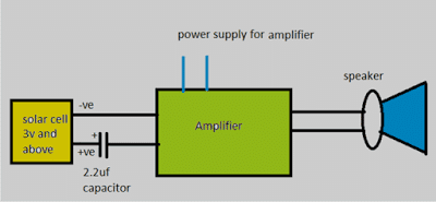
Here is a simple block diagram explaining LI-FI:
The Design:
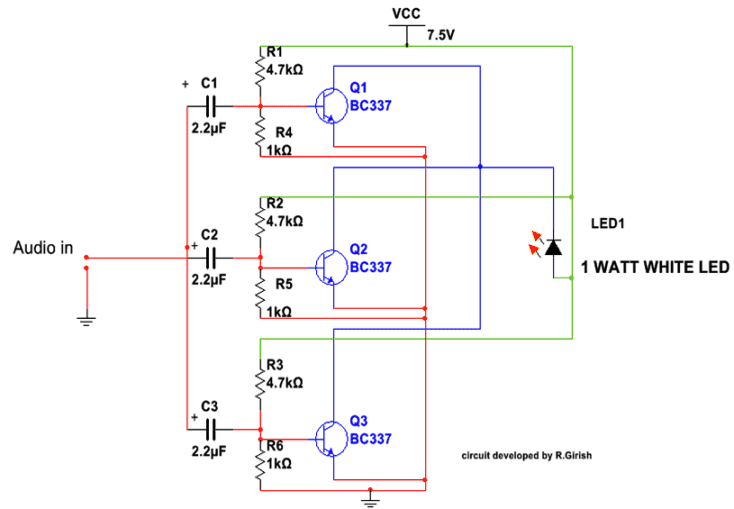
The circuit consists of two parts, which are receiver and transmitter. The transmitter consists of 3 transistors and few passive components paired with 1 watt LED. The transistors are configured as common emitter amplifiers which alters the LED brightness with respect to audio signal.
But changes in brightness due to audio signal will not visible to human eye. We only see static illumination of white LED. The receiver consists of a photo detector (here I used solar cell) which is paired with an amplifier. The sound output is given by the speaker.
The transmitter is transistorized amplifier which consists of 3 amplifiers connected in parallel to drive the 1 watt white LED.
Each transistor base consists of voltage divider which gives necessary bias for the individual transistor. The input stage has capacitors at each transistor’s base for blocking DC signals which could degrade the quality of output.
LI-Fi Circuit Diagram
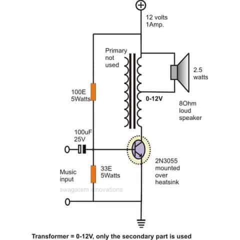
Update: The above design can be also tried using a single transistor as shown below:
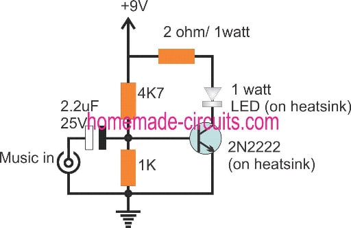
You can use a current limiting resistor series with LED if you want operate the circuit at higher voltage (say 12V).You can also use standard 0.5mm white LED with current limiting resistor. For an audio source you can use mp3 player, mobile phone or a microphone with pre-amplifier etc.
The receiver consists of a 6 volt solar cell (3 volts above works fine) in series with 2.2uf capacitor which is paired with an amplifier. The amplifier need not to be the same illustrated here, but you can use any amplifier lying around your house. But make sure it as good sensitivity.
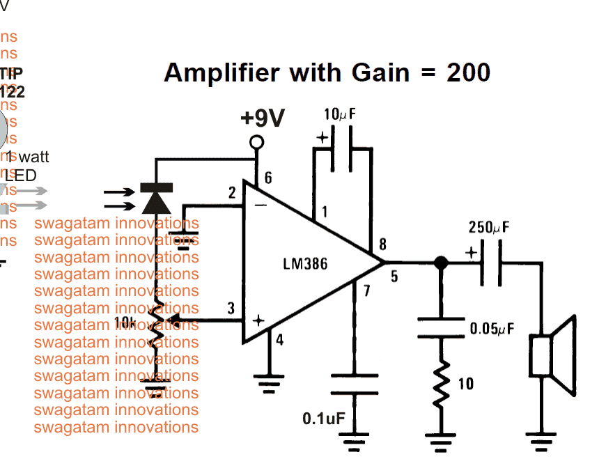
Amplifier Schematic
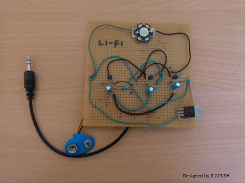
Here is author’s prototype
Li-Fi Video Clip:
You can use any amplifier with good sensitivity for receiver part. To test this circuit, go to a room where ambient light is dim and make sure no nearby electrical light source.
Place the 1 Watt LED parallel to solar cell. Turn ON the power supply for both transmitter and receiver, give audio input to transmitter, adjust the volume to transmitter. You can here clear audio sound on the receiving speaker.
The above explained Li-Fi circuit can also be tried using a photodiode as shown below, where the amplifier section is replaced with a LM386 amplifier circuit:
UPDATE:
Some Important Notes and Considerations Regarding the above Li-Fi Circuit
In this Li-Fi the LED does flicker, but it is in-significant for our eyes to detect.
If your eyes can detect those flickers, something wrong with the build.
The change in the brightness of LED due to the audio input is very small, but there is change in the brightness, where our eyes can’t detect.
If there is no audio input, the LED stays solid ON, the solar cell produce some voltage. The input capacitor at receiver blocks those DC signal giving almost zero voltage to amplifier.
When we apply audio signal at transmitter there will be change in the LED’s brightness (Very small). The solar cell replicates the small varying voltage, the capacitor will allow the small variation in voltage amplitude to amplifier and rejecting strong constant DC voltage.
The amplifier must have good sensitivity since the input is feeble. Probably that’s why many readers are commenting on loudness of the audio.
I have used old-school home theater’s amplifier which had very good sensitivity and the resulting output was LOUD and CLEAR.
Hii,
What is the use of 2N2222 transistor in the circuit diagram. Can you explain whole circuit diagram please I will be very thankful for that.
Please respond as soon as possible
Thank you in advance
2N2222 is configured to work like a simple common emitter amplifier circuit. It amplified and music across its collector so that the LED is able to respond according to the music amplitudes.
This is mind blowing, thanks for sharing.
Hello,
Have you got the procedure for finding why the particular values of resistor and capacitors
I will really appreciate you if you can provide the procedure or atleast the reference for it.
If you have the procedure do mail it to
14bm047sakshay@gmail.com
All the values are experimented to get optimal amplification…..if you alter the resistor values, the output amplification will be effected, similarly if you alter the capacitor again the amplification will get effected….the resistive divider limits the input amplitude or the peak voltage, the capacitor limits the current.
Does it need to turn on mobile data to play music in youtube?
Here the signals that are transmitted are analog i think so, then the output in led will be analog too so how this is lifi ?
The purpose of Li-Fi is to communicate signals or music via light, it does not need to be digital.
Thanks for sharing this is really helpful for me and also for my upcoming project. hope you add some more in future also. thanks for sharing
You are welcome kimmy.
Sir
Have u got projects on internet generation and transmission using LiFi
Ololo, sorry, I do not have any other article related to internet lifi other than this one.
Hi there!!!
for transmitter part we are using almost same components (as shown in figure with 3 transistors)…
for receiver part we are using solar panel (5V 1.25W) followed by amplifier circuit with LM386, however we have not used 2.2uF capacitor in series with solar panel…
our receiver part is probably not working as we are not getting any sound in speakers…transmitter part is working as we have tested it with 5 Hz test tone as audio input, we were able to see LED flickering
kindly help us…
Hi, please replace the photodiode with an LDR in the LN386 circuit, and make sure to connect a 2.2uF or any capacitor in the range, in series with the pin3 of the LM386
sir, I am working on the research project on Li-Fi. I would like to connect Li-Fi receiver to the FPGA . can you help me with the circuit diagram
I have a simple question … if we switch the transmitter and receiver between two devices does it works in lifi technology?
also, I found some devices on the internet they work with the help of USB. I would like to replace the USB cable.
Sai, Sorry I do not know much about FPGA technology, but any high frequency will be accepted and processed by this Li-Fi circuit.
As long as the input is a high frequency signal, the LiFi will work across the selected devices.
Bro i used a led strip instead of a led bulb and a 3v solar panel and now the lifi is not working where maybe the problem be where should i make a change in the led or in the solar panel?
Rahul, first build and verify the basic design which is explained above. If you succeed with that then we can proceed and modify it with an LED strip, and check the response!
I made the circuit as given above but used a 3v solar panel and it is not working should i use a 6v or 9v solar panel? Plz reply fast i have to submit it today evening.
Did you check your amplifier normally using a music input? First check whether your amplifier is actually working or not? Any solar panel will work for this application…just make sure no other light except the Li-Fi light falls on the light sensor (solar panel)
sir
i do not want the anologue experiment help with the minimal materials i need for this
moreso from my last post do i have the required material if not help me with what i need for the digital experiment perhaps i didnt find the article
may be you can try the following concept
https://www.homemade-circuits.com/lifi-internet-transmitter-circuit/
Thanks on the receipt of your wonderful detail swaga
Kindly help me with detail for the digital LiFi transmitter and receiver
Ololo, the explanation for a digital LIfi circuit is given in the above article, so please go through it for detailed understanding.
sir
i just got a 3 watts solar panel to be used as a photodetector, three 6 watts LED wifi panel bulbs,and fresnel lens for an amplifier
please is this enough for a room LiFi
internet
i realy want to know if the fresnel lens is a must since its in a room because its hard to get fresnel lenses in nigeria
help
ololo, the minimum things are already specified in the article, you will just need those minimum things for the experiment, fresnel lens may not be necessary, please do exactly as explained in the article.
hi swag …can i send data more then 1M mebe text file or a picture for 2meters ..and can i buy it and export the circuit
for iraq
Hi hassan, sorry this design supports only analogue signals, digital signal might not work correctly.
sir,
i’m a final year undergraduate student working on applications of li-fi: indoor positioning using lifi. can you please tell me how to use this circuit for positioning.
and what is the distance between tx and rx to be placed
Sunil, as long as the light sensor is able to receive the light from the LED it will work, the distance will not matter, but you will make sure that no other ambient light reaches the sensor…
Sir, can u please make some video showing connections and working of the project.
SIR SOLAR IS BETTER OR PHOTO DIODE IS FOR TRANSMITTER CIRCUIT
Gajendra, solar cell will be easier to configure, photo diode will require some technical consideration…so solar cell is the easier option.
both are equally good as far as results are concerned..
Hii swag
I make lifi Circuit same as your Circuit diagram from above. But from wheres i will provide power supply i dont know,
Means R1 connect to +ve and R6 connect to -ve of battery ??
Om, the Vcc line is the positive, and all the wires linked with this line are positive.
similarly all the wire links joined with the ground symbol are negatives.
use 5V as the supply
Hi deepak,
You can try: https://www.homemade-circuits.com/2016/02/how-to-make-simple-laser-communicator.html
Regards
hey there can u briefly explain the working of ur reciever and the components needed. I have a preamplified speaker and it a has 3.5mm jack input., Can i directly connect the solar panel to it?
hey, yes you can connect the solar module directly to the input of your amplifier circuit, but make sure no ambient light reaches the solar module except the light from your Tx LED.
thanks for the info swag.Does this mean that this system wouldn’t work in a well-lit room?
It won’t work if any other form of light reaches the light sensor of the receiver, because after all the light sensor is an ordinary light sensor and get activated with all forms of light.
and one more question….how many LEDs can we connect here.I am talking about those small LEDs which work at 1.5V.
divide the supply voltage with 1.5V, and you will get the max number of LEDs that can be accomodated in series
thanks, Swag. That means I will need 6 LEDs as I am using a 9-volt battery.
yes for a1.5V LED you can use anything between 1 and 6 LEDs with a 9V battery, a resistor will be required if the LED count is less than 6
thanks again swag .You are very helpful. I am almost done making the project. Now I need to finish the receiver part .I have solar panels from 2 calculators that I scavenged. Will that be enough to run the receiver?
You are welcome ATR, you can try those solar chips, it should work!!
The transmitter circuit started working as soon as I connected the battery. The LEDs lit up and stay ON with or without the music signal from my phone. Does this mean that it’s OK?
yes it is OK, please read the previous comments to get a detailed idea of the circuit.
Hey Swag, the preamplified speakers I told about in one of the previous comments are my old computer speakers which have an amplifier inside and a 3.5 mm jack coming out of it.
that’s fine ATR, just touch the 3.5mm pin tip, if that makes a loud noise on the speakers then your system is ready for the solar chip integration, which can be connected across the 3.5 mm jack’s relevant inputs.
hey swag the setup worked …I am getting audio output but i think the speakers are not good enough because the sound is very grainy.
That’s awesome ATR, the issue could be perhaps due very feeble output from the solar module, you can try adding a LM386 kind of amp in the middle to boost the solar chip output and then this could be fed to the amplifier for the final amplification, just a suggestion though!
sir ,
I am a student i have been working on lifi but i am facing an error that if we use white or green or any other led than the sound is coming very low It is coming loud on red led only.
Adarsh, the volume output is supposed to be directly proportional to the intensity of the light, so white LED should be more efficient than any other color, red cannot be more efficient than white, I think your red LED could be having more focusing power than the white LED and therefore giving better results…..you can try confirming the light power using the following method
https://www.homemade-circuits.com/2014/10/diy-led-brightness-and-efficiency.html
OK, that’s great! yes you can replace laser with the LED just make sure the V and I specs of the laser are correctly supplied.
I am glad you liked it.
the transistor can be any small signal transistor such as BC547 or 2N2222, and 8050 will also do.
make sure the LED lights up optimally during the presence of a music signal and shuts down completely in its absence…and also make sure no other light except the LED light falls on the light sensor. alternatively you can also try the LM386 circuit with an LDR for a more responsive performance.
Hi,
Thanks for quick reply.
I used BC338. The LED is always on even when there is no signal applied to it. Is it a problem? Would using BC547 gives better output than BC338. Though BC338 giving good LED Illumination.
I used 6v Solar Panel with 2.2 capacitor and fed to amplifier. The Signal received is very very low. I have to put full volume to hear some output.
Is it due to Solar Panel or due to BC338? Please help in the issue.
Also I do not have Solar Cell and nor could get Photodiode. What modification needed to use LDR to existing amplifier if I have to replace Solar Panel? quick help appreciated as I am sitting with LDR in hand.
Hi,
I thought the LED would be always ON and audio would be transmitting through it.!!!!
In one of your comments I read
“I guess you are referring to the first circuit in the above article, yes the LED will be lit while no signal is connected to the circuit, but as soon as you connect the function generator, the negative signals from it will begin shutting off the LED at the specified frequency rate and you will start seeing the required conversion from the LED.”
So I assumed the LED would be always on.
I was using 3 BC338, 1 Watt LED in the transmitter. In the Receiver end I was using 6v Solar Panel 300mA along with capacitor and A House Amplifier.
I did get audio signal to my amplifier but it is very very low even at full volume.
If my building has error or has to change the transistor then Please suggest a Circuit where LED would be always ON – With Signal or No Signal.
I would like to have my room illuminated always (with Signal or No signal) and also have Music transmitting when Signal fed.
HI deepak,
LED stays SOLID ON even when no signal input is applied to transmitter that’s the property of LI-FI:- Light and also Communication. Our eyes can’t pickup the flicker due to input signal. If it flicker probably no sufficient power to transmitter.
Regards
The LED should stay solid ON even while data is being transmitting. You should not see any flicker.
Hi GR,
Can you please briefly explain how will the LED respond to positive music peaks which may be above 0.6V, because the LED is already ON through R2?
OK, I think I got it, higher voltage pulses will push proportionately more current to the base of the transistor and produce equivalent change in the brightness.
Hi sir,
The LED does flicker, but it is in-significant for our eyes to detect.
If your eyes can detect those flickers, something wrong with the build.
The change in the brightness of LED due to the audio input is very small, but there is change in the brightness, where our eyes can’t detect.
If there is no audio input, the LED stays solid ON, the solar cell produce some voltage. The input capacitor at receiver blocks those DC signal giving almost zero voltage to amplifier.
When we apply audio signal at transmitter there will be change in the LED’s brightness (Very small). The solar cell replicates the small varying voltage, the capacitor will allow the small variation in voltage amplitude to amplifier and rejecting strong constant DC voltage.
The amplifier must have good sensitivity since the input is feeble. Probably that’s why many readers are commenting on loudness of the audio.
I have used old-school home theater’s amplifier which had very good sensitivity and the resulting output was LOUD and CLEAR.
I would suggest you past this comment in the article as update, if possible.
Regards
Thanks GR,
Yes since the response of the music pulses will be extremely rapid, the output cannot be detected by our eyes and we will be able to see a constant average illumination, but the solar cell and the amplifier will be able to extract the minute variations and reproduce it into the exactly same data as the input over the loudspeaker.
Actually the placement and the selection of the 2.2uF capacitor is interesting and crucial which helps to effectively vary the current into the base of the BJT which in turn causes the LED to change its illumination pattern as per the music, and since the BJT is a current controlled device becomes perfectly suitable for the application.!!
I’ll add your comment soon in the above article!!
HI sir,
yes, you got it..
Thanks sid, I am glad you liked the post, however I am really sorry, a simulation update might not be possible from me due to lack of time.
Can i ask mobile phone related question?
Thanks for your response,i want to be specific reason with what I will be buying in the market for the project.
Please give me the specifications to save me the stress of mixing things up.
Thanks
what exactly do you want to make using LiFi, I mean what kind of frequency do you intend to communicate with? please provide a detailed view
Good Morning,
I used Proteus to simulate the transmitter circuit and it worked with a sine wave generator as the input.
But during the implementation it did not work and when I later changed the input to an audio file,the led was not coming on.
The receiver circuit is not working as well,will appreciate it if you can guide my through.
My defense is next month and I haven't gotten to anywhere,though audio transmission using LiFi is cheap to my Lecturer as a final year project work,will as well appreciate it if you can recommend something better to me and guide me through it.
Look forward to your speedy response,time is not on my side again
It did not work because your implementation is incorrectly done.
if the LeD is not illuminating it simply means that your circuit is not biased correctly….and if the LED does not illuminate then how will the receiver respond?
either you must elevate the music input power or enhance the BJT stages in order to increase its sensitivity which perhaps can be done by converting the BJTs into Darlington pairs.
you can try the above suggestions.
Wow i am blessed by the wealth of knowledge here,had to read through all the comments, weldone sirs.
I am a final year student from the department of Electrical and Electronics Engineering in Nigeria,Want to use Lifi Technology as my final year project work. I am only acquianted with the theory but i need help and guidance with the practical implementation.
will appreciate it if i can get help and support from these, you can do well to connect with me on aroloyefolajimi@gmail.com.
Look forward to your response,thanks
Thanks Aroloye, complete practical implementation is already explained in the above article, if you have specific questions you can feel free to ask me here, I'll try to solve it….
I have connected the circuit and did not work so I drew it using the Livewire program but stopped the subject at the income I did not understand what the value of the income supposed to be in order to operate the circuit Note that I want to be a graduation project has been suspended in this section I hope you help me and thank you very much
Why is led always on in transmitter wheter there is sound or no sound
can we use a 12v alkaline battery for the power supply in the receiver?
The circuit works fine for frequency less than 7-8KHz square wave. It will start distort beyond that. Will you please tell me a circuit which work upto nearly 500KHz. Thank you
Hi Sujit,
for higher frequencies you may probably have to employ a BTL kind of amplifier for driving the LED, which is also referred to as Class D amplifier…it's a digital version of an ordinary amplifier and will be able to handle high frequency music in the PWM form.
will you please suggest any specific transistor for that and if possible circuit diagram.
thanx for reply
you can try the following concept
https://www.homemade-circuits.com/2013/10/class-d-amplifier-circuit-using-ic-555.html
Sir, myself Sujit Chatterjee. I am working on LiFi since 2016. I have to transmit signal 100Hz-1MHz square wave via LED. Whether the mentioned circuit will work for that range….
I was wondering if a setup like this using infrared would mitigate the problem of light interference from ambient light? The lights in my room are all LED. Also, what are your thoughts on stereo? Would a stereo setup require some micro-controller circuitry?
yes that's possible, but the advantage of using LED is that you are able to illuminate a given space while also transmit the data….IR won't fulfill this twin function.
for stereo you can use a pair of these set-ups but the signal will need to be modulated through a carrier signal within the two sources, otherwise the two lights could interfere with each other.
I would prefer to use visible light, however my lights are above me on a ceiling fan. To achieve using them I would have to devise some sort of PLC to the LED and then modulate the LED for the Li-Fi. That is WAAAY beyond my abilities so I thought since remote controls use infrared in bright conditions it might offer a solution with less interference. You said infrared is possible, but do you think it would be less affected by ambient light with the right components?
remote controls use a specific frequency and therefore ambient light is not able to affect its functioning, but for music the frequency range cannot be restricted and that could be a problem….
to counter this, the IR receiver sensor may need to be covered in such a way that it is able to receive the music signals from the IR transmitter but remains hidden from the ambient light.
Can I replace the LED with laser diode?
yes you can!
Hi gabriel,
You may refer this link: https://www.homemade-circuits.com/2016/02/how-to-make-simple-laser-communicator.html
Regards
I want circuit diagram
Really thanks for that information happy to learn from u more
you are welcome!!
you can probably implement it by using two of these amplifier circuits, one as the Tx, other as the Rx.
In Tx input join the 6 signal via diodes, at the output side connect two LEDs in parallel with opposite polarities (anti-parallel)…make sure each one has its own 1K resistor.
At the Rx input connect an LDR.
…sorry, if you are having 6 separate signals then that becomes very simple, just make 6 separate Tx/RX modules using the design that's explained in the above article and get the required results.
I forgot to provide the link in the previous comment….here it is
http://www.nxp.com/documents/data_sheet/TDA7052A_AT.pdf
Sir I am working on data transfer through rj45 connector…basically I want to convert 6 pin to 2 pin and give it to LED and then decide and convert again 2 pin to 6 pin…sir how can I do the transmission section please help me
What photodetector should i use for the transmission of a video signal ?
video signal cannot be transmitted using the above circuit….
Can you please tell me what is the ic present on the photo you posted on the transmitter circuit and please provide me the full schematic of the transmitter circuit….
Hey ! It works for me ! But i have a few questions:
What's the name of that type of system ?
How did you find those values of resistor and capacitor ?
Which calculations did you do ?
Thank's !
thanks, the answers to your questions will require long explanations, which may not be possible here…
I made it thanks
can u provide us with the full schematic diagram of the tx and rx
i really need them
ahmedaly10026@yahoo.com
i feel sorry for you having to answer all the stupid questions you get on this site. you should setup some ground rules for not answering questions that could be answered by a simple google search and 10 seconds of time. The comment sections are just filled with stupidity and ignorance because you bother to answer questions like, "sir, i am working on the research project on lifi so please provide me more information regarding lifi." Seriously, don't answer that shit. It makes this site, which is filled with great information, look stupid as it is catering to the worst form of ignorance. If you want to help them, help them to realize it is quicker and more efficent for them to type nearly the same thing into google and find the answer and much more. If he would type "information regarding lifi" into google he would have got the URL you shared and a ton of other information. Now he has to come back and ask "where can i get more information about lifi" because you didn't teach him to learn, you just babied him and gave him the answer which is like cheating in school. This site is a great place to learn, but the comments are a great place to want to kill yourself over stupidity.
I appreciate your suggestion, and I quite agree with you.
eventhough I too prefer skipping such questions I finally end up answering them just to make sure nobody gets hurt and feel ignored.
Sir, I am an IT student don't have much knowledge about electronics. Can you pls answers my questions.
To my knowledge we Input internet connection through a ethernet cat 5 cable. The analog signal will be converted to light bean and the receiver will receive the light beam and convert them to analog signals which can be fed to a laptop againa via cat 5 cable.
But I dnt see any ethernet cable socket in the diagram.
Sir please share ur email id. I have some doubts.
sir, i am working on the research project on lifi so please provide me more information regarding lifi.
Suraj, you can refer to the following link for more info
https://en.wikipedia.org/wiki/Li-Fi
alternatively if you just Google "Lifi", you will be able to find a diversified info regarding the subject
Sir ,in audio jack there are thee wire 1.input 2.ground and what is the third one??
Sanjay, the biggest terminal is the common ground, the other smaller two are for the left/right inputs.
Sir, in I didn't understand stand the ckt of the transmissitor why we use 3 transistors ????
Sanjay, it's for better amplification only
Hi everyone. Communication is sending and recieving informations in two ways. How does Li-Fi work in the opposite direction? Who can help me explain this problem? Thank a lot.
What type of communication are you referring to? because Li-Fi is supposed to be used inside closed rooms
Thank for your answer. But I still don't understand about how Li-Fi works when we just use our telephones. How we can send and receive message each other? Thanks.
May be it is through fiber cables…
Communication is sending and recieving informations in two ways. How does Li-Fi work in opposite direction? Who can help me explain this problem? Thank a lot!!
The simpliest way I presume it would be having the same couple of circuits on both sides, as as transfer and receiver at the same time. In that case you would have to need a controller device capable of responding to whatever signal you are sending after evaluating it.
you can salvage it from an old calculator device…
Is it necessary to use a solar cell can i use a LDR instead. What would be the difference. Expecting the answer soon. Thank you!
LDR can be used in the last circuit instead of the photo diode…
which type of amplifier can we use for our receiving circuit,can we make one of that and if yes then how??
Thank you so much sir. It worked fine for me, but the volume is really low. Ill try and change the speakers.
for the transmitter part can we use 9v Vcc instead of 7.5v?
I am glad it worked for you Ananth, yes 9V can be also used instead of 7.5V.
you can try a better amplifier design for improving the sound quality
Hello sir, I have designed exactly the same circuit as yours, but i am using function generator instead of Audio in. But i am getting more than 8 volts output. Can you please help me with that. Which components should i change or is this circuit only for supplying audio signals? I need to ask one more thing that we are supplying positive VCC directly to LED terminal, is it fine?
Hello Abdullhaq, the circuit can be use for transmitting all kinds of frequencies, so it should work with your function generator output also, first make sure that your function generator output has only pulsating DC and no constant DC…and the solar cell gets no other ambient light except the function generator frequency light
Thanks sir, But how should i limit the output voltage to around 3.2Volts that can be handled by LED. Because i am getting more than 8 volts output even without attaching function generator.
I am assuming you have connected the LED with the function generator output, in that case you can connect a resistor in series with the LED to limit current and optimize the volts automatically, however if this 8V is constantly available then that's incorrect and your function generator could be faulty according to me.
alternatively you can connect a 10u/25V capacitor in series with the LED resistor…and a another 10K from LED/capacitor junction to ground.
…sorry I think I got you wrong, I guess you are referring to the first circuit in the above article, yes the LED will be lit while no signal is connected to the circuit, but as soon as you connect the function generator, the negative signals from it will begin shutting off the LED at the specified frequency rate and you will start seeing the required conversion from the LED.
Hi spyros,
I found the resistor values by trail and error method. I used different values of resistor and I found the above specified values optimal. Initially I chose BC548, but too weak to handle 1watt LED, so gone with stronger transistor BC337 these info can be found in the datasheet.
regards
connected a stereo jack (3.5mm) to the radio. I connected the ground pin of the jack to the cathode of a small LED. The left channel pin was connected to the anode of the LED. In addition, I connected a 9V battery with a 1k ohm resistor to the anode and cathode of the same LED. This was my transmitter circuit.
In the receiver circuit, I simply connected a solar panel (6V) to the speaker. I powered the speaker through wall socket (230 V AC current). It worked. I was able to transmit audio.
Now, I want to be able to transmit a video, in the same way you did in your TED talk a few years ago. This time, my input is an AV jack from an old DVD player. I connected the ground wire of the AV cable from the DVD player to the cathode of LED and the positive wire to the anode of the LED. In addition, I connected a 9V battery with resistor to the LED. As above, I connected the solar panel (6V) directly to the AV cable of a mini screen which takes AV input. The screen is powered by a wall socket.
This time however, nothing shows up on the screen. I tried using an LED of higher brightness (1 watt). Now, only an icon shows up on the screen which says "AV 1 detected" for a short while and then disappears altogether.
I would be obliged if anyone explained to me how you achieved video transmission through Light Fidelity.
appreciate your efforts, however a video signal cannot be transmitted through a LED so easily, because a video signal may have many complex frequency data embedded together which cannot be transmitted or received without special encoders and decoder circuits. Music is a single frequency data therefore it may be much easier to send music through a Li-Fi circuit, but not a video signal
How am I supposed to connect this with the internet? :/
it has the modulation circuitry responsible
please respond
No, the above circuit is not modulated with a carrier wave.
there is no modulation ?????? and how you chose the value of resistors and capacitor and if possible send me the Shema block and the role of each block answers please it's urgent
Can you show ptototype transmiter and receiver in detail, please your help thanks
Sir, if I am giving a signal from a signal generator to the input should I do any changes in the transmitter . If yes can you plz tell me those changes. Thank you
Amarnath, no changes would be required for the signal generator signal, it's also a kind of frequency so will work just as a music input is supposed to work
Thank you sir, I was able to give the input via a signal generator but it seems I'm only able to transmit and reciece square waves.. Other waves(above 0.016V) are saturating the output.. If I decrease the gain of the OP amp will it work ?
Thanks again
Hi Amarnath, the gain of the shown LM386 amp circuit is already set at the max 200 range.
you can probably try to optimize the volume control for getting improved results, and reduce distortions.
Hello,
What kind of LED and photodiode do you use ?
any standard photodiode will work.
We got the audio output
Thanks a lot for solving our doubts 🙂
I am glad it worked for you…congrats!
Why are we getting a pulse waveform across led?
Why does it change if we swap collector with emitter?
In the common emitter mode you will get square wave pulsed waveform, while in the common collector mode or emitter follower mode you will get an exact replica of the fed music… reinforced with higher current
Can i use photo diode or ldr instead of solar cell
yes you can after suitable modifications
What shoud i change if u use photo diode
Plz help me out im trying this since 5 days
I'll try to update a new diagram tomorrow using a photo diode.
sir, which specification should we see while selecting photodiode for above application.
We have made the transmitter and receiver as mentioned.
We found that the data is getting transmitted through led but we aren't able to receive that using solar panel ie. The voltage drop across solar cell remains almost constant
Now what shall we do to increase sensitivity of the panel?
it should be a solar cell not a solar panel, try with a solar cell which are normally used pocket calculators.
and first make sure your amplifier is working OK, test it separately by feeding a music input from a cell phone's headphone socket
why can’t we use solar panel?
if you want to use a solar panel, you can try connecting it between pin3 and ground of LM386….no need of connecting coupling capacitor in this case.
What's that 100e 5watt, its solar panel.
And can I use 12v2amp for receiver
that's a resistor, you can try some other amplifier circuit if you find this one difficult or crude in its layout
12V 2 amp will do
May I know the specifications of the amplifier?
Will any audio amplifier do?
Is it necessary to modulate the input?
I am in first year of engineering and doing this circuit as my project, so would you please guide or suggest any modifications to the circuit?
any audio amplifier can be used for the conversion.
modulation will result in a better and a stable Light output from the LED but the circuit design could be a bit complex.
Am so happy SWATAGAM just because i managed to receive sound to my receiver end . thanks very much AM CALLED KAKUMBA DAVIS
that's great Davis, I am glad you could succeed with the above explained circuit.
What is the circuits for receiver and transmittier
Just for confirmation …thanx
What is the 3v & abovel solar cell value of power & current.
it's the specification of the solar cell…it's also not so critical.
sir,Which capacitor used in solar celll 2.2uf or 100uf ?? In block diagram 2.2uf is used & reciver circuit 100uf used. Which is the correct one?
Nikita, the value is not critical, you can use any electrolytic capacitor at the shown input position of the amp.
Sir ,
U sure this circuit works? Don't we need any microcontrollers for doing lifi??
The concept is dead easy and you won't need anything complex for a basic design as above, however in the above design the light would fluctuate with music so it must be superimposed on a carrier frequency and then transmitted. the receiver side would also need a circuit capable of extracting the superimposed music from the carrier signal for the expected LiFi output
isn't possible to make lifi from my wireless home broadband? if its yes can you send me a video? thanks
The carrier frequency is the frequency of the LED.