In this article I have explained how to make a simple laser communicator circuit for sending and receiving data through laser beam.
Laser has been a boon since its invention. Laser is used in wide variety of applications, from Blu-ray driver to high powered cutting torch. There are also many classifications of laser technologies.
Here we use them for communication and receive an audio signal at the receiver.
Laser technology is used in satellite communication system, optic fiber communication system etc. The principle behind laser communication is series of pluses applied at transmitter and decoding the pulses at receiver end. This article explains how to make one at your hobby lab.
The setup consists of two parts, a transmitter and a receiver. The transmitter converts the audio signal to pulsating light with respect to input.
The receiver is an amplifier paired with a solar cell as photo detector. Due to pulsating light input to the receiver the voltage across the solar cell varies with respect to audio input.
However we won’t see pulsating light, we only see static illumination of laser beam. This faint signal is picked up by an amplifier.
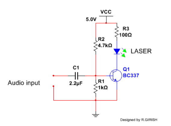
The Transmitter Circuit
The laser communicator transmitter circuit is simply built using a single transistor and a few passive parts such as resistors and capacitor.
It is basically a single transistor preamplifier which accepts an analogue or digital frequency input and transfers the same data to a laser bulb.
The laser beam from the laser bulb now starts pulsating at the same rate as the data transferred by the transistor. Thus, the modulated signal on the laser is transmitted into the atmosphere as light vibrations.
The transmitter shown below consists of single transistor amplifier with laser module. C1 is DC current blocking capacitor, R1 and R2 gives necessary bias for the transistor.
R3 is current limiting resistor; you may adjust the value of this resistor to get right amount of current flow and brightness for your laser.

A laser communicator receiver circuit can be now positioned at any distance within the laser beam's reach and the laser information could be decoded and amplified by the receiver back into the original form.
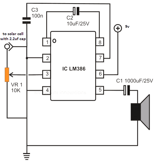
The Receiver Circuit
Block Diagram
The following image shows the block diagram of the laser communicator circuit. We can see that a solar cell is attached at the input of an audio amplifier.
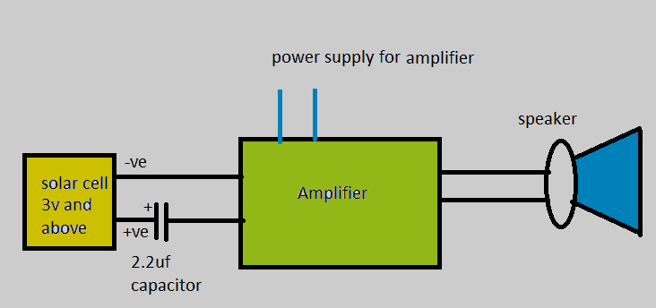
The information encoded in the laser beam is focused on the solar cell.
The solar cell converts the encoded information in the laser light into equivalent electrical pulses.
These electrical pulses are amplified and decoded by the audio amplifier and reproduced into a connected loudspeaker.
If the laser light has an encoded music in it, then the amplifier will decode it as an amplified equivalent music output.
If the laser beam carries a modulating speech signal then the same will be reproduced after amplification into the loudspeaker.
If the laser beam has encoded logic data, the same can be visualized over an oscilloscope by replacing the loudspeaker with an oscilloscope.
We have used an LM386 amplifier circuit for the proposed laser communicator circuit, but you can feel free to use any other amplifier circuit for the same functionality.
Checking Laser Diode Specifications
If you purchase a laser module from online or retail store or anywhere, please check the data sheet or specification for your laser module. If you violate those specifications you may damage your laser module. Please adjust R3 and input voltage according to the specifications.
Don't use laser modules from DVD writer or any laser rated class 3B. They shoot high power laser beam which could damage your solar cell and not safe for your eyes and skin.
You may use toy laser or laser pointer that has 3 button cells. These lasers are commonly available at stationary stores.
You may use any amplifier lying around your house which has good sensitivity. It is not mandatory to use the same amplifier illustrated here. The audio source may be from your Smartphone, MP3 player, iPod etc.
To test this simple laser communicator circuit go to a room where electrical lights are switch off, if you don’t you will hear humming noise on your amplifier. Power up both the transmitter and receiver, input the audio signal to transmitter and direct the laser beam to solar cell, you will hear clear sound at speaker.
You may use active high pass filter to filter out the humming noise at receiver. This circuit is capable of carrying transmitted signal around 100 meters depending how powerful your laser beam is.
Hi sir, i have made the circuit work, im doing it as a part of my research, are there any other research papers i can can refer to? on this topic?
That’s great Mithul, thank you for your efforts.
I do not have any research papers on this topic, but if you have specific questions, you can ask me, I will try to solve them for you.
Hi Swagatam…this Laser based data transmission system is great. But just wanted to know how can we increase the range of transmission to 400 meters or 500 meters??
Thank you Jitendra, if the laser light focus is able to reach up to 400 meters, then this circuit will respond at 400 meters distance, so it depends how much distance the laser light is able to reach. You can test the distance during night time in total darkness.
Thank you..will surely try and let you know…
Sure, no problem!
hi..I am Jitendra from West Bengal. I need your help in one of my project.
You can ask your question!
I want to share a video of a project. I am from a non technical background. Can you tell me the parts being used in this project and also the probable circuit diagram.
If the video does not have a circuit diagram then it can be difficult for me to provide the parts list. Instead of the video link you can explain the purpose and function of the circuit, if possible I will try to help! However you will have to learn the basics of electronics to understand the concept, only then you will be able to build it successfully.
This basically consists of a geared 12 V DC mortor moving in both directions controlled by a processor on wireless command. I am not able to identify or understand working principle. Probably you with your expertise can identify the parts and working of the circuit. I have pictures of the whole setup.
433 MHz Wireless remote controls are available easily and cheaply from market, which can be configured with an external DPDT relay to move a DC motor reverse forward direction.
This is what I can suggest. The range will be around 10 meters.
Mind me sharing the screen shot of the parts?
The image of the remote control is shown below: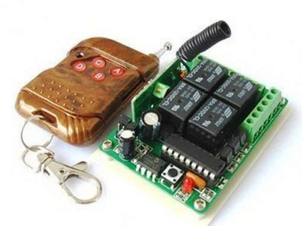
" rel="ugc">
The remote control has 4 relays which can controlled by the 4 buttons of the of handset.
Two relay remote is also available.
How can I share the images of the components?
You can upload the images on any “free image hosting” site and share the link here. I will check them out.
Please check the images
https://ibb.co/CbMYVtP
https://ibb.co/Bg7fMS1
I cannot understand why such a complex big box is used for the receiver? It can be solved using small remote receiver which I showed you earlier.
I saw the video, for the board up/down you can use the same concept which is shown in the following link:
https://www.homemade-circuits.com/simple-gate-openclose-controller-circuit/
S1 and S2 will need to be controlled with remote control relays.
Thank You so much. God bless
You are welcome!
You are welcome Jack!
Zeeshan, sorry, I do not have this information with me at this moment!
Which type of laser u r using in this project ? 3-5v input laser is coming in market , but which u r using for this project nd how many voltages r given to laser ?
All the information is given in the article…please read it.
Thank you sir. A similar and also interesting project are the lifi devices. I propose this idea for a future post.
You are welcome Rosario!
Goodmorning Sir. Could digital data be transmitted with this circuit? Thanks.
Hi Rosario, yes that may be possible if the LM386 audio amplifier is replaced with a class D type amplifier