The post presents a simple transformerless 1.5V DC power supply circuit which can be used for powering wall clocks directly from mains, and also keep a stand by back-up cell fully charged for enabling an uninterrupted operation of the clock even during mains failures. The idea was requested by Cheekin
Warning: This circuit is not isolated from mains AC and therefore is extremely dangerous to touch in powered condition, users are advised to apply extreme caution while handling it or testing in an uncovered position.
The Design
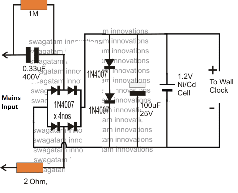
The figure shows a simple 1.5V transformerless power supply circuit for wall clocks that would never allow the clock to stop due to a depleted battery as it would keep running from the mains and also be reinforced with a battery power to ensure that the clock does not stop even during a mains failure.
The below shown design is a simple transformerless power supply using a 0.33uF capacitor as the input current limiter component in order to restrict the mains current to a modest 16mA.
Circuit Diagram

Hopefully this current will keep the clock ticking satisfactorily and also keep the attached Ni/Cd cell trickle charged and ready for an emergency back up.
If the 0.33uF does not provide adequate current for the operations, you can increase it to a higher value which just satisfies the application needs.
The indicated 1.5V transformeless power supply for a wall clock is able to develop the required 1.5V DC at the output with the aid of the two forward biased 1N4007 rectifier diodes across the (+), (-) terminals of the supply, which effectively shunts the massive 330V mains (@ 20mA) to a nominal 1.5V DC.
The inclusion of the two shunting diodes also ensures an entirely surge free supply for the clock and the charging cell, and therefore the design is relieved from other conventional forms of surge protection devices.
How it Works
Briefly the 1.5V transformerless supply circuit for clocks can be explained as follows
The mains input current is dropped to a lower 20mA by the 0.33uF/400V capacitor.
The bridge rectifier converts the above low current input to a low current DC variant, which is further acted upon by the two 1N4007 diodes which shunts the DC to a fixed 1.5V approximately.
This 1.5V / 20 mA DC is finally used for operating the desired wall clock, and also for charging a connected 1.2V Ni/Cd cell which reverts its DC each time mains fails, ensuring a failproof uninterrupted supply for the clock so that the unit never stops due to any adverse reasons.


With over 50,000 comments answered so far, this is the only electronics website dedicated to solving all your circuit-related problems. If you’re stuck on a circuit, please leave your question in the comment box, and I will try to solve it ASAP!