This universal automatic battery charger circuit is extremely versatile with its functioning and can be adapted for all types of battery charging and even for solar charge controller application.
Universal Battery Charger Main Features
A universal battery charger circuit must have the following main features included in it:
1) Automatic battery full charge cut-off, and automatic low battery charging initialization, with corresponding LED indicator warnings.
2) Adaptable to all types of battery charging
3) Adaptable to any given voltage and AH rated battery.
4) Current controlled output
5) Step charging 3 or 4 step (optional)
Out of the above 5 features the first 3 are crucial and become the mandatory features for any universal battery charger circuit.
However along with these features an automatic battery charger must also be extremely compact, cheap, and easy to operate, otherwise the design could be quite useless for folks with less technical knowledge, making the "universal" tag get nullified.
I have already discussed many diversified battery charger circuits in this website, which includes most of the salient features that may be essentially required for charging a battery optimally and safely.
Many of these battery charger circuits used a single opamp for simplicity sake, and employed a hysteresis option for implementing an automatic low battery charging restoration process.
However with an automatic battery charger using hysteresis in opamp adjusting the feedback preset or variable resistor becomes a crucial procedure and a little complicated affair especially for the newcomers..since it requires some relentless trial and error process until the correct setting is finalized.
Additionally setting up of the overcharge cut-off also becomes a tedious process for any newcomer who may be trying to achieve the results quickly with his battery charger circuit.
Using Fixed Resistors instead of Pots or Presets
The present article specifically focuses on the above issue and replaces the pots and presets with fixed resistors in order to eliminate the time consuming adjustments and to ensure a hassle free design for the end user or constructor.
I have already discussed one earlier article which elaborately explained hysteresis in opamps, we are going to use the same concept and formulas for designing the proposed universal battery charger circuit which will hopefully solve all the confusions related to the building of a customized battery charger circuit for any unique battery.
Before we move ahead with an example circuit explanation, it would be important to understand why hysteresis is required for our battery charger circuit?
It's because we are interested to use a single opamp and use it for detecting both the lower discharge threshold of the battery as well as the upper full charge threshold.
Importance of Adding a Hysteresis
Normally, without hysteresis, an opamp cannot be set for triggering at two different thresholds which may be quite wide apart, therefore we employ hysteresis to get the facility of using a single opamp with a dual detection feature.
Coming back to our main topic regarding designing an universal battery charger circuit with hysteresis, I have explained how we can calculate the fixed resistors, so that the complex Hi/Lo cut off setting up procedures using variable resistors or presets can be eliminated.
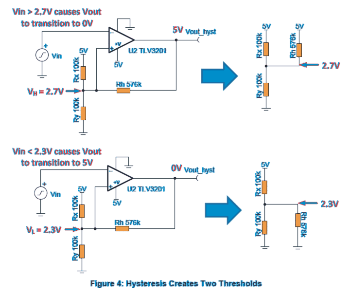
To understand the basic operations of hysteresis and its related formula we first need to refer to the following illustration:


In the above example illustrations, we can clearly see how the hysteresis resistor Rh is calculated with respect to the other two reference resistors Rx and Ry.
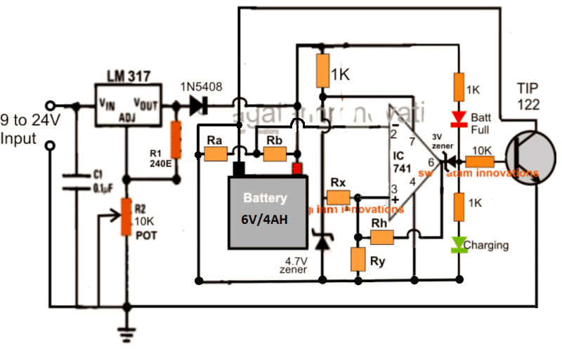
Now let's try to implement the above concept into an actual battery charger circuit and see how the relevant parameters may be calculated for getting the final optimized output. We take the following example of a 6V battery charger circuit
In this solid state charger diagram, as soon as pin#2 voltage becomes higher pin#3 reference voltage, the output pin#6 goes low, switching OFF the TIP122 and the charging of the battery. Conversely as long as pin#2 potential stays below pin#3, the output of the opamp keeps the TIP122 switched ON and the battery continues to charge.

Implementing the Formulas in a Practical Example
From the formulas expressed in the previous section we are able to see a couple of crucial parameters which needs to be considered while implementing it within a practical circuit, as given below:
1) The reference voltage applied to Rx and the opamp supply voltage Vcc must be equal and constant.
2) The selected upper battery full-charge switch off threshold and the lower battery discharge switch ON threshold voltages must be lower than the Vcc and the reference voltages.
This looks a little tricky because the supply voltage Vcc generally is connected with the battery and therefore it cannot be constant, and also it cannot be lower than the reference.
Anyway, to tackle the issue we make sure that the Vcc is clamped with the reference level, and the battery voltage which needs to be sensed is dropped to a 50% lower value using a potential divider network so that it becomes less than the Vcc, as shown in the above diagram.
The resistor Ra and Rb drop the battery voltage to a proportionate 50% lower value, while the 4.7V zener sets the fixed reference voltage for Rx/Ry and the Vcc pin#4 of the opamp. Now things look ready for the calculations.
So let's apply the hysteresis formulas to this 6V charger and see how it works out for this example circuit:
In the referred 6V circuit above we have the following data in hand:
Battery to be charged is 6V
Upper cut off point is 7V
Lower restoration point is 5.5V.
Vcc, and reference voltage is set to 4.7V (using 4.7V zener)
We select Ra, Rb as 100k resistors to reduce the 6V battery potential to 50% less value, therefore the upper cut off point 7V now becomes 3.5V (VH), and the lower 5.5V becomes 2.75V (VL)
Now, we need to find out the values of hysteresis resistor Rh with respect to Rx and Ry.
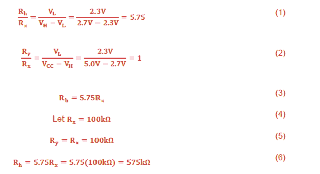
As per the formula:
Rh/Rx = VL / VH - VL = 2.75 / 3.5 - 2.75 = 3.66---------1)
∴ Rh/Rx = 3.66
Ry/Rx = VL / Vcc - VH = 2.75 / 4.7 - 3.5 = 2.29----------2)
∴ Ry/Rx = 2.29
From 1) we have Rh/Rx = 3.66
Rh = 3.66Rx
Let's take Rx = 100K,
Other values like 10K, 4k7 or anything could do, but 100K being a standard value and high enough to keep the consumption reduced becomes more suitable.
∴ Rh = 3.66 x 100 = 366K
Substituting this value of Rx in 2), we get
Ry/Rx = 2.29
Ry = 2.29Rx = 2.29 x 100 = 229K
∴ Ry = 229K
The above results can be also achieved using a hysteresis calculator software, just by clicking a few buttons
That's it, with the above calculations we have successfully determined the accurate fixed values of the various resistors which will make sure that the connected 6V battery automatically disconnects at 7V, and restarts charging the moment its voltage drops below 5.5V.
For Higher Voltage Batteries
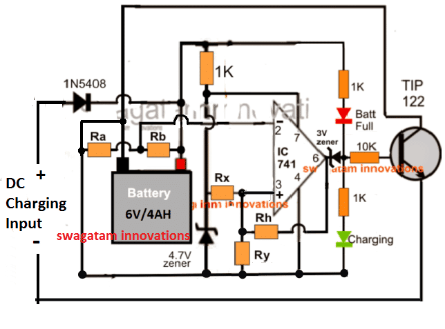
For higher voltages such as for achieving 12V, 24V, 48V universal battery circuit, the above discussed design may be simply modified as given below, by eliminating the LM317 stage.

The calculation procedures will be exactly the same as expressed in the previous paragraph.
For high current battery charging, the TIP122 and the diode 1N5408 may need to be upgraded with proportionately higher current devices, and change the 4.7V zener to a value that may be higher than 50% of the battery voltage.
The green LED indicates the charging status of the battery while the red LED enables us to know when the battery is fully charged.
This concludes the article, which clearly explains how to make a simple yet universally applicable battery charger circuit using fixed resistors to ensure extreme accuracy and foolproof cut offs across the set threshold points, which in turn ensures perfect and a safe charging for the connected battery.
Dear Swagatam,
I discovered your site not long ago, and I have to say its very interesting and instructive. I live in Haiti but I studied Computer Science in Mexico through the years 2000-2004, there I had a brief introduction in Electronics. I’m planning to designing a new circuit and I’d like to solicit your help because I want it reliable thus with industrial strength. The specifications are as follow:
We will use a 12 volts Motorcycle batteries of up to 7 Ah.
A 18 volts solar panel with 1.1 Amp/hr.
The batteries will be charged by the solar panel with over-charged protection
and an auto cut-off implemented.
The circuit should allow a user two USB ports 1.0 Amp and 2.1 Amps Respectively so he/she can charge a cell phone. Another port of 19 volts 2.4 Amps so he/she can charge a laptop. And yet another port to connect a 12 volts Motorcycle led light. (I have tested those led an the batteries can keep them on for 12 hours easily. They seems to be 3 Watts).
The critical part of the circuit is that the batteries of about 84 Watts should never reach certain limit of discharge by either the laptop or the cell phone. For instance if the batteries is full and then a laptop is plugged in to be charged, once the batteries reach 30 Watts, the circuit should disable both the laptop and cell phone socket leaving only the port for the led light.
One more way I wish you could help me out is how I can find the electronic components that I might need, since it’s complicated to buy from Haiti online.
I sincerely will appreciate all the help you might bring me in this endeavor.
Dear Michel, You can try the following basic design
At the output side of the 1N5408 diodes you will have to add a 12V to 19V boost converter.
and a 12V to 5V buck converter for charging the laptop and cell phone units respectively.
Swagatam,
Thank you so much for your help. The circuit you propose looks great. In fact, since I shall run some test on it, what voltage I should look up from the batteries that would correspond to 30 Watts approximately left on it. I don’t know how to find that out. I also want to understand, from the circuit diagram, in order to have the 2 Amps current, should I just combine usb2 and usb3?
Thank you Michel! The 30 watt may correspond to some lower discharge voltage level, which you will have to find out with some experimentation. The Rx value basically decides the maximum current that can be derived from the battery. For 2 amps the Rx value can be 0.7/2 = 0.35 Ohms 2 watts. The right side 10k preset must be set to cut off the load through the relay at this discharge threshold.
The left side 10k preset decides the over charge cut off, while the 100k presets decide at what point the relay cut off situation must be restored back into previous operational mode.
The USB ports are in parallel, so in any circumstances the 2 amp cannot exceed from these ports no matter whether they are used in combined manner, or separately
Thank you so much Swagaram for your precious explanation. I should have replied earlier, but I have a limited internet connection. I’m studing the circuit diagram throughoutly. In fact I found on your site an article that explain how to use fixed resistors without “presets”. I found it very interesting, maybe you might find the time to give me some help there too. I feel confused on that point. I sincerely appreciate your valuable work.
Thank you, I think you are referring to the above circuit itself, although the article has explained the concept thoroughly, if you have specific issues, I’ll will try to solve it.
Very nice on your part Swagatam! I’am working on the caculations, I think by next week I will be posting my results so you can check them out to see if everything is correct.
Thank you Michel, please go ahead and let us know how it works.
Swagatam,
I have double checked the circuit you proposed to me and I have come to the conclusion that the circuit you took as example to demostrate Hysteresis in the above article they are not similar. My understanding about hysteresis is that there are basically three resistors: Rx, Ry and Rh we must find their values according to a set a parametters. However, in the circuit that we are concerned about it’s not clear which resistor is Ry or Rh. All we know we aim at replacing both 10K presets (left and right) and the 100K pot. In case the two circuit are totally different and based on what you thougth about hysteresis I found that for a 12 volts, 7Ah battery with a upper cut off at 14.1 volts and a lower restauration point at 11.6 volts. If we choose Rx to be 100K, Rh = 483K and Ry = 290K.
By the way I have a question. To a fully charged battery corresponds a 14.1 voltage, what current will correspond to that battery if it is a 7Ah?
Thanks again for your help.
Michel, The 10k preset corresponds to Ra, Rb, and the pin3 must be configured exactly as explained in the article, however I think using presets and with some experimentation will be easier to set up the circuit compared to the calculations.
For 7 Ah lead acid battery f SMF battery the maximum charging should not exceed 1 amp
Swagatam,
I know very little about electronics and am very grateful for this diagram and explanation. I would like to apply it to charging a Rayovac NiMH 14.2V iRobot vacuum cleaner battery. The charging station is no longer working and replacement is more than $40.00.
Input charging voltage is 22.4VDC. I’m guessing battery V-Low would be 12-13V (or less ?) and V-High would be 15-16V (or higher?)
Would this circuit be applicable? And what do you estimate the component costs to be?
Thank you,
Stevan Iungerich
Thank you Stevan, this circuit is a universal design and can be applied for all batteries. However your cut off thresholds must be accurately known, approximate values can damage your battery.
Thank you.
Hello, i’m going to use this circuit for my inductive charging project to charge a 22,8V/5.7AH LiPo Battery. I’ve already chosen replacements for the 1N5408 diode and the TIP122, but i don’t know what i should do about the 4,7V and 3V. What value would fit them?
By the way , do I have to change anything else for a 5~6A current?
The 3V zener can be removed, and instead the green LED can be shifted from its existing position to the base of the transistor (in series with the 10K)
The 4.7V zener can be still used as is.
make sure to calculate the other parameters as explained in the article.
use TIP142 instead of TIP122 for 6A
sir can i get the full circuit diagram of mppt based solar charger .
Hi Ganesh, I have explained a few concepts in this website, you can use the search box on top and check out the articles as per your preferences.
Kindly explain full working of circuit
It's already explained in the article…if you have any specific question, you can ask them…
Hai sir…
I'm 15-0-15v 1A transformer for charging 12v 7ah battery…
Fullwave rectifier I'm using…
I need the capacitor value sir..
Now im uaing 25v 470uf takes to much time charge 10hrs..
Pls tell the value of capacitor..
Is there any formula available..
Hi Kesava, 15V can be very high after rectification for a 12V batt
use 12-0-12 instead, and use any high value capacitor in the range of 2200uF with the bridge…that will do the job.
a lead acid or an SMF will normally require 10 to 14 hours for charging correctly…so it's OK and recommended.
Okay sir
Thank u
Hi Swagatam
I think Ry and the LEDs are connected incorrectly.
Here is how they should be:
https://1drv.ms/i/s!AoTuA4fWLcNglkCD2VY-a0XD2n8w
Thank you Abu-Hafss, seems like a careless mistake made by me while drawing the finalized diagram, I'll correct the diagram soon….
Bare bare deshon mein aisee chhoti moti baaten hoti rehti hen 😉
yes 100% accurate…
Is this circuit is tested and 100% accurate for develop???
happy new year SWAGATAM ,thanks for that great circuit and information , now what is the current rating for the dc input to the circuit, thanks
Wish you the same Davis,
the DC input current must be approximately 1/10th of the battery AH if it's a Lead Acid…or same as the AH if it's a Li-ion