In this post we try to investigate how to design a SG3525 full bridge inverter circuit by applying an external bootstrap circuit in the design. The idea was requested by Mr. Mr. Abdul, and many other avid readers of this website.
Why Full-Bridge Inverter Circuit is not Easy
Whenever we think of a full bridge or an H-bridge inverter circuit, we are able to identify circuits having specialized driver ICs which makes us wonder, isn’t it really possible to design a full bridge inverter using ordinary components?
Although this may look daunting, a little understanding of the concept helps us realize that after all the process may not be that complex.
The crucial hurdle in a full bridge or a H-bridge design is the incorporation of 4 N-channel mosfet full bridge topology, which in turn demands the incorporation of a bootstrap mechanism for the high side mosfets.
What's Bootstrapping
So what’s exactly a Bootstrapping Network and how does this become so crucial while developing a Full bridge inverter circuit?
When identical devices or 4 n-channel mosfets are used in a full bridge network, bootstrapping becomes imperative.
It's because initially the load at the source of the high side mosfet presents a high impedance, resulting in a mounting voltage at the source of the mosfet. This rising potential could be as high as the drain voltage of the high side mosfet.
So basically, unless the gate/source potential of this mosfet is able to exceed the maximum value of this rising source potential by at least 12V, the mosfet won't conduct efficiently. (If you are having difficulty understanding please let me know through comments.)
In one of my earlier posts I comprehensively explained how emitter follower transistor works, which can be exactly applicable for a mosfet source follower circuit as well.
In this configuration I have explained that the base voltage for the transistor must be always 0.6V higher than the emitter voltage at the collector side of the transistor, in order to enable the transistor to conduct across collector to emitter.
If we interpret the above for a mosfet, we find that the gate voltage of an source follower mosfet must be at least 5V, or ideally 10V higher than the supply voltage connected at the drain side of the device.
If you inspect the high side mosfet in a full bridge network, you will find that the high side mosfets are actually arranged as source followers, and therefore demand a gate triggering voltage that needs to be a minimum 10V over the drain supply volts.
Once this is accomplished we can expect an optimal conduction from the high side mosfets via the low side mosfets to complete the one side cycle of the push pull frequency.
Normally this is implemented using a fast recovery diode in conjunction with a high voltage capacitor.
This crucial parameter wherein a capacitor is used for raising the gate voltage of a high-side mosfet to 10V higher than its drain supply voltage is called bootstrapping, and the circuit for accomplishing this is termed as bootstrapping network.
The low side mosfet do not require this critical configuration simply because the source of the low side mosets are directly grounded. Therefore these are able to operate using the Vcc supply voltage itself and without any enhancements.
How to Make a SG3525 Full Bridge Inverter Circuit
Now since we know how to implement a full bridge network using bootstrapping, let’s try to understand how this could be applied for achieving a full bridge SG3525 inverter circuit, which is by far one of the the most popular and the most sought after ICs for making an inverter.
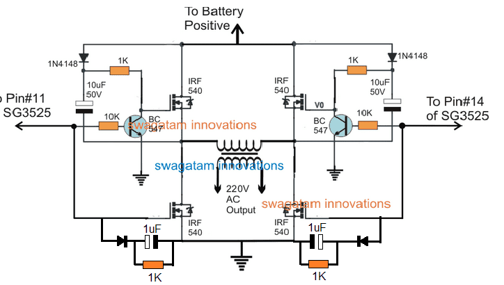
The following design shows the standard module which may be integrated to any ordinary SG3525 inverter across the output pins of the IC for accomplishing a highly efficient SG3525 full bridge or H-bridge inverter circuit.
Circuit Diagram
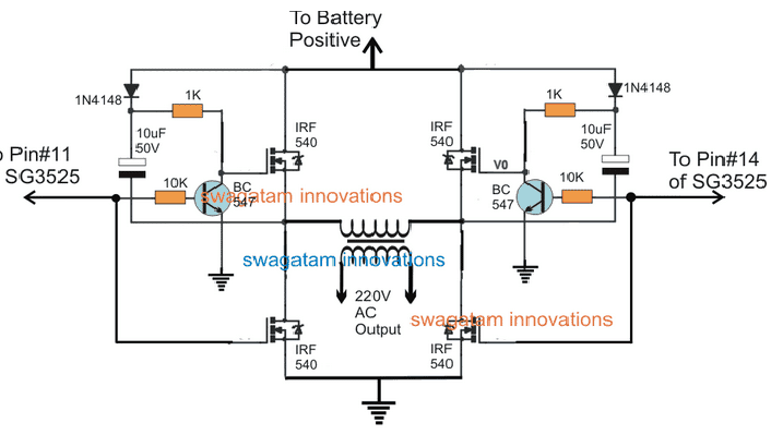
Referring to the above diagram, we can identify the four mosfets rigged as an H-bridge or a full bridge network, however the additional BC547 transistor and the associated diode capacitor looks a bit unfamiliar.
To be precise the BC547 stage is positioned for enforcing the bootstrapping condition, and this can be understood with the help of the following explanation:
We know that in any H-bridge the mosfets are configured to conduct diagonally for implementing the intended push pull conduction across the transformer or the connected load.
Therefore let’s assume an instance where the pin#14 of the SG3525 is low, which enables the top right, and the low left mosfets to conduct.
This implies that pin#11 of the IC is high during this instance, which keeps the left side BC547 switch ON. In this situation the following things happen withing the left side BC547 stage:
1) The 10uF capacitor charges up via the 1N4148 diode and the low side mosfet connected with its negative terminal.
2) This charge is temporarily stored inside the capacitor and may be assumed to be equal to the supply voltage.
3) Now as soon as the logic across the SG3525 reverts with the subsequent oscillating cycle, the pin#11 goes low, which instantly switches OFF the associated BC547.
4) With BC547 switched OFF, the supply voltage at the cathode of the 1N4148 now reaches the gate of the connected mosfet, however this voltage is now reinforced with the stored voltage inside capacitor which is also almost equal to the supply level.
5) This results in a doubling effect and enables a raised 2X voltage at the gate of the relevant mosfet.
6) This condition instantly hard triggers the mosfet into conduction, which pushes the voltage across the corresponding opposite low side mosfet.
7) During this situation the capacitor is forced to discharge quickly and the mosfet is able to conduct only for so long the stored charge of this capacitor is able to sustain.
Therefore it becomes mandatory to ensure that the value of the capacitor is selected such that the capacitor is able to adequately hold the charge for each ON/OFF period of the push pull oscillations.
Otherwise the mosfet will abandon the conduction prematurely causing a relatively lower RMS output.
Well, the above explanation comprehensively explains how a bootstrapping functions in full bridge inverters and how this crucial feature may be implemented for making an efficient SG3525 full bridge inverter circuit.
Now if you have understood how an ordinary SG3525 could be transformed into a full fledged H-bridge inverter, you might also want to investigate how the same can be implemented for other ordinary options such as in IC 4047, or IC 555 based inverter circuits, …..think about it and let us know!
UPDATE: If you find the above H-bridge design too complex to implement, you may try a much easier alternative
SG3525 Inverter Circuit which can be Configured with the the above Discussed Full Bridge Network
The following image shows an example inverter circuit using the IC SG3525, you can observe that the output mosfet stage is missing in the diagram, and only the output open pinouts can be seen in the form of pin#11 and pin#14 terminations.
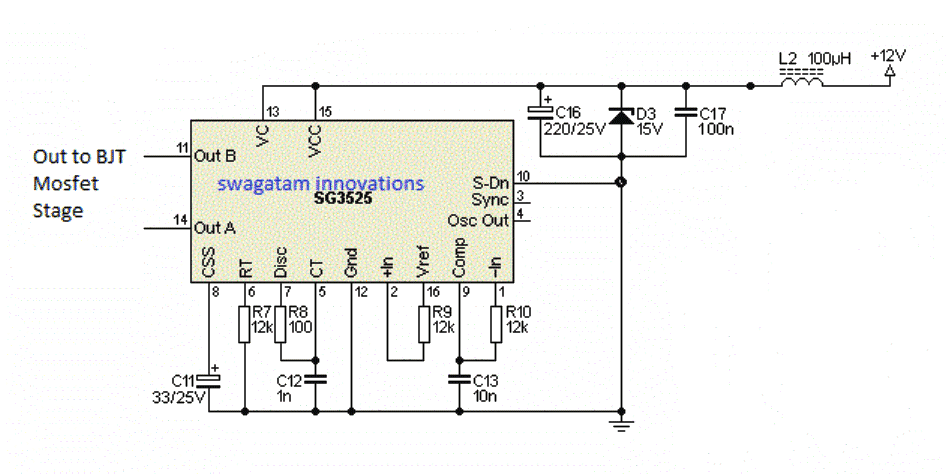
The ends of these output pinouts simply needs to be connected across the indicated sections of the above explained full bridge network for effectively converting this simple SG3525 design into a full fledged SG3525 full bridge inverter circuit or an 4 N channel mosfet H-bridge circuit.
An Easier Full Bridge Inverter using P-Channel MOSFET
If you think the above SG3525 full bridge inverter circuit using 4 N-channel MOSFETs is too complex for you to handle, then you can rather try the following simpler design.
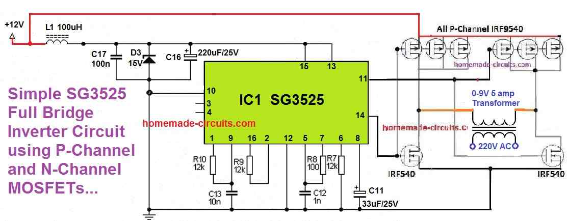
It replaces the high side N-channel MOSFETs with P-channel MOSFETs, thus eliminating the need of a bootstrapping network.
You can see 3 to 4 P-channel MOSFETs are connected in parallel on the high side, while only single MOSFETs are used on the low side.
This is because P-channel MOSFETs have relatively higher RDSON resistance specifications compared to the N-channel MOSFETs, which have very low RDSON resistance.
To make sure the P-Channel MOSFET's RDSON resistance matches with the N-channel counterpart, more number of P-channel MOSFETs are connected in parallel, which makes sense.
Feedback from Mr. Robin, (who is one of the avid readers of this blog, and a passionate electronic enthusiast):
Hi Swagatum
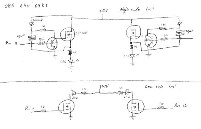
Ok,just to check everything is working I separated the two high side fets from the two low side fets and used the same circuitry as:
(https://www.homemade-circuits.com/2017/03/sg3525-full-bridge-inverter-circuit.html),
connecting the cap negative to the mosfet source then connecting that junction to a 1k resistor and an led to ground on each high side fet.Pin 11 pulsed the one high side fet and pin 14 the other high side fet.
When I switched the SG3525 on both fets lit up momentarily and the oscillated normally thereafter.I think that could be a problem if I connected this situation to the trafo and low side fets?
Then I tested the two low side fets,connecting a 12v supply to a (1k resistor and an led) to the drain of each low side fet and connecting the source's to ground.Pin 11 and 14 was connected to each low side fets gate.
When I switched the SG3525 on the low side fet's would not oscillate until I put a 1k resistor between the pin (11, 14) and the gate.(not sure why that happens).
Circuit diagram attatched below.
My Reply:
Thanks Robin,
I appreciate your efforts, however that doesn't seem to be the best way of checking the IC 's output response...
alternatively you can try a simple method by connecting individual LEDs from pin#11 and pin#14 of the IC to ground with each LED having its own 1K resistor.
This will quickly allow you to understand the IC output response....this could be done either by keeping the full bridge stage isolated from the two IC outputs or without isolating it.
Furthermore you could try attaching a 3V zeners in series between the IC output pins and the respective full bridge inputs...this will ensure that false triggering across the mosfets are avoided as far as possible...
Hope this helps
Best Regards...
Swag
From Robin:
Could you please explain how{ 3V zeners in series between the IC output pins and the respective full bridge inputs...this will ensure that false triggering across the mosfets are avoided as far as possible...
Cheers Robin
Me:
When a zener diode is in series it will pass the full voltage once its specified value is exceeded, therefore a 3V zener diode will not conduct only as long as the 3V mark is not crossed, once this is exceeded, it will allow the entire level of voltage that's been applied across it
So in our case also, since the voltage from the SG 3525 can be assumed to be at the supply level and higher than 3V, nothing would be blocked or restricted and the whole supply level would be able to reach the full bridge stage.
Let me know how it goes with your circuit.
Adding a "Dead Time" to the Low Side Mosfet
Thee following diagram shows how a dead time could be introduced at the low side mosfet such that whenever the BC547 transistor switches causing the upper mosfet to turn ON, the relevant low side mosfet is turned ON after a slight delay (a couple of ms), thus preventing any sort of possible shoot through.
Hillary says
Hi, good morning. I made the inverter, it worked for some time and stopped. I even had to make more boards but all ended up same way. what should I do?
Swagatam says
Please check what went wrong, check the MOSFETs, and the IC an,d try to find out what is blowing…I will try to figure out the cause…
Hillary says
good day, I made the inverter as seen but there was a ticking sound in the mosfet side, how do I get rid of the sound please
Swagatam says
Hillary, It is difficult to say the reason of the ticking sound without practically seeing your circuit. Is there anything heating up?
Hillary says
there is nothing heating up at all. I had to make a separate set of MOSFET, but same thing happened
Swagatam says
Please remove, or disconnect the transformer and check again…
Chinomso says
Hello Mr. swag, i have a 2.5kva inverter I built using your first diagram design, bit I would like to replace the bc547 transistor with a Darlington transistor like tip122 to help improve on the gate current to be able to withstand more load. Do you think it’s necessary, if it is, how do I integrate the tip122 in the circuit (with it’s base resistor)?. Thanks slot
Swagatam says
Hi Chinomso,
The load is handled only by the MOSFETs, so upgrading the BC547 is not necessary.
Moses kwagam says
thank you swagatam for your quick response. I am curious not to blow the high side fet- I build one already but the capacitor is 47uf 50v and can 35uf 100v be used?
Swagatam says
Moses, actually I have not yet tested the design, i got this from one of the online forums, yes 35uf 100v should be good according to me.
Moses kwagam says
Good day mr Swagatam, how is work and the family? I want to verify something: in choosing the right capacitor for a bootstrap network, is the voltage of the capacitor more important than its capacitance or the capacitance should be considered first. For example what should I consider first when choosing the right capacitor for 24vdd supply for full bridge inverter?
Swagatam says
Thank you Moses, everything is good so far.
The capacitance value is more important, which can be anywhere between 10uF and 22uF.
For 24V Vcc, the capacitor voltage rating can be around 50V, as per the standard norms.
Arthur electricals says
pls can I connect a 22k across the gate and source of only the low side MOSFET and eliminate the high side since the high side has a switching transistor 547. or should I connect it all because for the high side the source is connected to drain of low side so am getting it confused on how to connect it on the high side MOSFET since it has a 547 with the MOSFET pls.
Swagatam says
You are right, the a gate/source resistor might not be relevant to the high side MOSFETs due to the presence of the bc5477 transistor, therefore you can use the resistor only for the low side MOSFETs…
Chinomso says
Sorry Mr. Swag for asking much. I forgot to state that my oscillator IC is sg3524, does the signal matter here?
Swagatam says
It doesn’t matter, because the basic working of both these ICs are identical.
Chinomso says
Hi Mr. Swag,
I built a full bridge inverter using your above explained design. However, I made use of irf3205 MOSFETs in parallel since I intend to drive the winding on 5000watts automatic voltage regulator transformer. I also used 100uf capacitor for the high side. The issue is that, the system works fine on a low low current battery input, such as 12v 14a source, but burns the whole MOSFETs on a 12v 200a battery source. Could the problem have come from the transformer our 100uf capacitor?. Also how could the high side capacitor be measured to attain smooth switching?.What do I need to improve on to make this work well?. Thanks
Swagatam says
Hi Chinomso,
Calculating the high side bootstrapping capacitor can be quite complex, here’s the actual formula to calculate it:
https://www.homemade-circuits.com/wp-content/uploads/2019/01/full-bridge-bootstrap-capacitor-formula-1.png
However, normally this value can be anywhere between 10uF and 22uF.
To prevent the MOSFETs from burning you could try a few things.
1) Check whether the current drawn by the transformer is too high or not.
2) Implement soft-start for the IC SG3525 so that the MOSFETs are not subjected to sudden current inrush.
3) Add a 10k resistor across gate/source terminals of all the 4 MOSFETTs.
4) Add reverse protection diode across the drain/source terminals of all the 4 MOSFFETs
Let me know if that helps.
Arthur Electricals says
How can this h-bridge circuit be powered with a 24v battery is their any changes with the boost capacitor, diodes and dead time value
Swagatam says
You can disconnect the anodes of the 1N4148 diodes and feed a 12V to these anodes through a 7812 IC, and supply the 24V only to the drains of the High side MOSFETs.
MOSES says
So this setup works well even though the transformer isn’t a center tap one
Swagatam says
It is a Full bridge inverter circuit so center tap transformer is not required here.
Chinomso U says
Hi Mr Swagatam,
I’ve built a 1.5kva inverter with the Hbridge system and it working well, and in reverse, I could charge my battery from the mains. But here’s the thing; the charging is not effective, especially when the mains voltage goes lower. I would like to install a feedback using an optocoupler, please do help me out in this, as a diagram would be more helpful. Thank you so much in anticipation
Swagatam says
Hi Chinomso,
You asked this question earlier and I have already answered you, please check your email for the link, it might have gone into your junk mail..
Ahmad Sadek says
Hello, Iam aiming to design a circuit to invert 18V DC input to AC output at high frequencies such as 50KHz in order to transmit it wirelessly then re convert into DC at the receiver to charge a battery, how can I increase or decrease the frequency using the topology you introduced if possible. Thanks in advance
Swagatam says
Hello, your concept is not feasible, battery charging requires high current which is not feasible using wireless transmission.
Ahmad Sadek says
Yes I understand but I will be having a very small prototype for university it will not require actual charging I just need to transmit any sort of power.
Swagatam says
Wireless electricity transmision may be possible only for a short distance of a few inches or a foot. As the distance increases the efficiency decreases. What distance are you looking for?
Ahmad Sadek says
Yes I have a maximum distance of 25 cm no more.
Swagatam says
In that case you can use the search box at the top and search for wireless phone and wireless LED
Jack Bugayong says
Hi Swagatam,
May I know the output frequency and wave form of this project. Is it 60hz out put and pure sinewave?
Thank you.
Swagatam says
Hi Jack, the output frequency can be adjusted by suitably adjusting the R7, C12 values in the following diagram:
https://www.homemade-circuits.com/wp-content/uploads/2017/03/sg3525-4.png
Output will be a square wave
Jack Bugayong says
Thank you so much for swift reply.
Hillary says
I must again recommend your good works Mr swag, thanks a lot. my question is, can this circuit work for microcontroller inverters?
Swagatam says
Thank you Hillary,
I am not sure how the above circuit can be used with a microcontroller inverter. I will try to investigate and let you know.
Momoh Hassan says
Which side is the high side and do I connect the feed back
Swagatam says
The top side mosfets are high side mosfets. Feedback can be connected on pin#10 of the IC, by disconnecting it from ground and then configuring it with a bridge rectifier and resistive divider network.
Momoh Hassan says
From which pin of the SG3525 can I connect the feed back sir
Swagatam says
You can use pin#1 for the feedback control, as indicated in the following diagram:
https://www.homemade-circuits.com/wp-content/uploads/2019/04/feedback-1024×460.png
Nnadi says
How can this H-bridge be done using ir2110 driver ic with sg3525
hiren says
hi sir,
i want to try full bidge induction heater with sg3525 ic to drive igbt with help of 316j can you help me about it.
is this safe or not for igbt .
Swagatam says
Hi Hiren,
I do not have an SG3525 based induction heater circuit, but I have a different IGBT based circuit which you can refer in the following article:
Induction Heater Circuit Using IGBT (Tested)
Celal TOPRAK says
hi sir can you chechk the circuit. its not working.
Swagatam says
Hi Celal, I checked the full bridge diagram which you sent me, but it will never work because it uses 4 N channel mosfet without a bootstrapping network.
Celal says
How I can I do it. I don’t know. may you help me with it because I did a lot of circuits like this and non of them worked. If you can help me I’ll be so glad.
Swagatam says
The full bridge is already explained in the above article which you can try. Or you can refer to the following article:
Simplest Full Bridge Inverter Circuit
Baker says
I want to drive 1000w DC motor in the place of transformer in any way with n-channel MOSFETs to drive pwm with DIR ,please help me,and thanks,with my expects
Swagatam says
You can try the following concepts:
https://www.homemade-circuits.com/simplest-full-bridge-inverter-circuit/
Baker says
Thanks for good job ,send send to me please,not very difficult principal circuit ,,,full H-bridge with 4N- channel MOSFETs to drive 1000watts DC motor,and thank you at all,with my expect.
Swagatam says
Thank you, the above explained circuit is very easy to build…
Ayodeji says
Can this work for the sinewave inverter explained earlier?
Swagatam says
It can be converted to sine wave by chopping the low side mosfets with SPWM
Sani salisu says
Thank you very much
Earnest says
So what can we use to replace that transformerand still performer the same function….
Earnest says
So what can we use to replace that transformer?
And I couldn’t find this IC SG3525 on Proteus library ….pls how can I get it
Swagatam says
You will have to use the following concept:
https://www.homemade-circuits.com/how-to-convert-3-phase-ac-to-single/
sorry I don’t use softwares so can’t help with proteus issue.
EARNEST says
pls i need a circuit diagram design on transformer less automatics voltage regulator.
that is the project am working on and I’m facing some difficulties on it
Swagatam says
Sorry, I don’t have this design with me right now.
EARNEST says
if we dosnt want to use that transformer what else can we use to replace it and still get 220v at output.
and this IC component is found in proteus for simulation where can we get it
Swagatam says
without transformer you cannot get 220V from 12V
Earnest says
Okay….what if we generate 214v from bridge rectifier and use it as an input to the H BRIDGE circuit, instead of 12v…so is it possible to get stable 220 output without transformer
Swagatam says
Yes that’s possible but the output will turn into a square wave
mesut says
dear Swagatam; I redrawn the circuit and succeeded. but as a result of many trials, I found the most ideal values on the circuit by experimenting. I use 100uf instead of 10uf. Instead of 1k, I use 2.2k, 1w or 2w mosfets (irf840), even without cooling. It works for 8 hours, the temperature is super (21khz)
Swagatam says
That’s great Mesut, I am glad you could improve the H-bridge design with some modifications in the part values. If possible please provide the drawing through an external link.
Kintu hussein says
Thank you sir I’m reading your ideas but are so teaching and valuable,infact am going to like site , becoz I love electronics
Swagatam says
Thank you Kintu, I appreciate your thoughts!
Samson says
Hello sir swagatam
I’m very interested in one of the inverter welding mention diagram that you shared but some parts of it like L1and L2 is being closed please can I get the direction on how to connect it.
Swagatam says
Hello Samson, please post your question under the article you are referring to.
Peter says
Hi Swagatam,
I am very grateful for all the information you have provided me. I have build a lot of your projects. So thanx for that. Just one question. The circuit mentioned in this site (which i love) i have build and even added more mosfets with great success. My question : i want to convert this 12v project to 24 or even 48 volts. What i don’t understand is whats the point of putting on a 24v battery and then just adding say a 7812 to protect the ic or adding a dc to dc step down converter. At the end of the day everything just comes back down to 12v.
Am i missing something or can you help by upgrading this particular circuit to 24v. i Don’t want a center tap circuit as your full H-bridge is much more efficient to me.
Thanx very much for always answering my questions.
Regards
Peter
Swagatam says
Thank you Peter, Glad you found the projects helpful. 12V or any lower level voltage is suggested to safeguard the IC since most ICs are not built to handle 24V or 48V. Such ICs are only used as an oscillator source for feeding the mosfet or BJTs. The actual 24V or 48V is used with the transformer and power devices to boost the power in that order.
Higher voltage at the output stage ensures proportionately lower current, which in turn means cooler transistors, and more compact inverter size….comparatively for lower voltages such as 12V units, the current, size and heat dissipation will be much higher.
peter says
Thank you for the input
So how do i feed 24v or 48v to the mosfets without damaging the ic. Since i will be using a voltage regulator to step down the voltage for the ic like a 4047 (15v max). so the 4047 outputs wil still be around 6v each which does not solve my problem. I saw a few of your circuits were 24 or 48v was applied but that was with a center tap transformer. i would like to implement higher input voltages to your h-bridge circuit.
Does that make any sense., or am i lost. i don’t wanna compromise the h-bridge for a center tap
If you can show me how my battery connection would look like regarding the above h-bridge circuit i will be grateful.
Thanx again
Peter
Swagatam says
The output of 4047 or any similar IC will be almost equal to its supply voltage, So if you are using 12V for the 4047, its ON time will be almost 12V, which is sufficient for the MOSFETs.
In the above h bridge, you can isolate the diode anodes and connect them with the 12V, and connect only the drains with the 24V or 48V battery.
Before this make sure to test the full bridge with 12V first, just to confirm its working.
mesut says
dear peter I converted this h bridge to pcb but it didn’t work. Can you share how you did it?
mesut says
dear friend.Swagatam why?h bridge 2pcs p channel mosfets 2 n channel mosfets are not made cross way.I’m reviewing all the circuits. But no complete result was found.
Swagatam says
Hello Mesut, using 4 n channel is the most efficient method of implementing a full bridge circuit, you can use n channel and p channel also by appropriately matching their RDson values.
mesut says
Thanks for the quick response. I have now researched (RDS ON) it is very different. I’m working on wireless energy. My goal is to run at 20khz. I succeeded with 2 mosfets. I want to try the h bridge to develop it. That’s why I’m doing research. can you update the h-bridge picture..sorry for the english.
Swagatam says
For p channel and n channel bridge circuit, you can try the following topology:
mesut says
Anyone running this h bridge circuit?
because i prepared pcb but it didn’t work. The circuit is not working. Do you have a trial drawing?
thanks for the answer. I made a h bridge drawing pcb, but it didn’t work. 1 mosfet is getting hot. There is no heat for the mosfets.
Swagatam says
The concept used in the bridge network is correct you can verify it from anybody, however I have not tested it myself, the idea was taken from one of the forum discussions.
If you are having difficulty with the above design you can try a simple p-chanel N-channel mosfet bridge.
mesut says
I’m irf9640 and irf630 rds very close what is your opinion. I’m very undecided h bridge pcb did not happen.
Zuredu dady says
Hi, I do repair inverters with center tap transformers but most of the transformers now a days is no more center tap so I will like you to give me a circuit using sg3524n on how to drive the transformers without center tap
Swagatam says
Hi, It is already explained in the above article.
Zuredu says
The transformers when I plugged them into light , 12v input battery reads 6v, 24v input battery reads 12v.
So my question is if I put in the circuit you gave me, will it charge?
Swagatam says
Which circuit are you referring to….?
Zuredu says
From SG3525 full Bridge inverter diagram, I built it, it was OK but can’t charge.
What should I do to make it charge batteries?
Swagatam says
There are many charger circuits explained in this blog, you can use any one of them to charge your battery
Dady says
I tried using SG3524, but my sg got blown up. So what should I do?
Thanks
Michael says
Can this H-Bridge topology be adapted to work from high voltage rail (rectified 220v ac)?
I can see a bootstrap challenge. Perhaps you will be kind enough for another version?
Swagatam says
It looks difficult to implement high voltage in the proposed circuit, you may have to employ a specialized full bridge IC for that!
faith jumbo says
Please I built this full bridge inverter using sg3525 with this circuit this is what I’m observing if I test the oscillator board every is working fine and I have 50hz but when ever I link the oscillator board to my MOSFETs that’s the switching unit the frequency changes and keep fluctuating to different frequency and if I link the transformer to it, it will burn the MOSFET please what could be the possible cause to this
Swagatam says
Please use an oscilloscope to test the frequency, duty cycle etc, DMM can give misleading results.
faith jumbo says
Actually I did test with my mini oscilloscope it give accurate value of 50hz and the wave form is correct but when ever I connect transformer to it, it will bow up my MOSFET so I was confused which one to believe oscilloscope or DMM
Swagatam says
Scope is correct, DMM is not. Try increasing the dead time, an try implementing all that’s mentioned in the following article:
How to Protect MOSFETs – Basics Explained
Kingsley says
Hello Mr. Swagatam.
Greetings sir.
Please I have an issue that borders me so much. I made a 5.5KVA inverter which is being used to power a 2.5KVA SUMO (water pump), a deep freezer of 0.7kw, and other lighting points, and FAN, TVs in the house. But the problem is that each time the whole appliances are powered at once, the output filter capacitor blows and this also burns the whole MOSFET in the inverter. I have used 104, 400V in parallel with 225, 400V X rated capacitor to filter the output and it burns, I replaced the with 2.2uf, 275 MKP capacitor and it lasted for about 5 days and the same problem occurs again.
Please help rescue me from such trouble. what value of filter capacitor will I use for a 5.5KVA inverter? Or is it appropriate to remove the filter entirely (i.e do away with the output filter)?
Swagatam says
Hello Kingsley,
Good quality capacitors should never blow, especially when they are correctly rated. Try using 630V metallized polyester type capacitors and check the response again.
Zuredu says
Pls I need a link explaining parts or section and working principles of the sections.
Example drivers part, buffer part, etc
Last day example if inverter is working but not charging battery, check this part.
Thanks
Engr Lucky says
Obviously a bomb. Pls practice your circuitry before publicising it. Mere looking at the IN4148 with 1k resistor connected to the gate of ir540, you will simply understand that the ir540 drain to source is constantly closed with Direct current. Dis will blow up the fets
Swagatam says
Don’t worry nothing will blow up here, you merely looked at the diode/resistor but failed to notice that the input to the BC547 base are alternatively switching, which means vertical MOSFETs can never be ON at any instant, so the MOSFETs can never burn….Now I hope you have understood that the circuit is fine to use….
Peter says
Hi, Sir
Thank you very much for the H-bridge circuit diagram. Its much more efficient than the center tap circuit.
My question is, do you have a circuit diagram for a bigger inverter, by that i mean something with more watts output. I used to same 12v-0v 6amp tranformers in parrellel but that only helped to share the load.
Thank you
Peter Ferreira
Swagatam says
Thanks Peter,
For bigger transformers you just have to upgrade the MOSFET and the battery power rating appropriately.
Wilson says
Hello swagatan, am very happy for the good work you’re doing for us here, my question is, what if am using a microcontroller and not sg3525
Secondly, does the above network works similar with IR2110.?
Swagatam says
Thank you Wilson, any flip-flop oscillator can be used as the input source, and it should work. You can use a microcontroller based oscillator, IC 4047, BJT astable, or any similar all should give the intended results, just make sure to add an appropriate deadtime
Peter Jubb says
Dear Swagatam,
SG3525 Full Bridge Inverter Circuit
I have studied the circuit with great interest, as I am wanting to produce a 1kW design using the SG3525.
Having been out of the electronics industry for many years, my memory and knowledge is being stretched to the extreme !
I can follow the description given generally, however, would appreciate your help in understanding what the discharge path for the capacitor is ( referred to in item 7)
7) During this situation the capacitor is forced to discharge quickly and the mosfet is able to
conduct only for so long the stored charge of this capacitor is able to sustain.
As I see it, the FET has a High gate impedance, so the discharge cannot be via. the gate / source junction, so I am a little confused.
Also, the 10uF capacitor and 1k resistor give around 7mS time constant, which seems very excessive, as the system is operating with a PWM frequency of 114kHz (according to data sheet and components shown) giving 57kHz transformer frequency – surely the capacitor would only need to hold the charge for 1/2 cycle (just under 10 uS).
As a side issue, I also want to run from a 60 volt battery pack to keep the current reasonable, as I will have 4 x floating 1kW units running together, feeding a 4kW grid tie inverter. 60 volt rail will result in the gate-source voltage being exceeded on the upper FET’s, so plan to use two back to back 15v zeners to clamp the gate – source within the 20v limit.
I am obviously misunderstanding the situation somewhere with the bootstrap circuit and would appreciate some help prior to committing to the build and risking components !
(Sorry for the long text)
Peter
Swagatam says
Dear Peter, the capacitor discharges when the BC547 and the low side MOSFETs are switched ON, in this situation the capacitor leads are shorted with only the 1k resistor in the path.
The 10uF is not a calculated value and will need to be optimized by the user as per their preference, nevertheless it is intended for a 50 Hz frequency. The SG3525 circuit is only for reference purpose and its components will need to be adjusted for getting 50 Hz output.
For more info regarding the bootstrapping you can go through the following article:
https://www.homemade-circuits.com/h-bridge-bootstrapping/
Peter Jubb says
Hi Swagatam,
Thank you so much for the rapid response and answer, which has clarified things – very much appreciated.
Peter
Swagatam says
You are welcome Peter!
Ruwan says
I have 24v, 220v hbridge type transformer ( without center tapping). which of your circuit can use for making an inverter by using the above transformer and also as a spwm?
Livingstone says
If i input 330VDC at load voltage,will I have output as AC without using transformer on the load side?
Swagatam says
Yes that’s correct.
gulayakbas54@hotmail.com says
swagatam , ıf I Show the my pcb schematic , Could you look after about okey or not ?
But for the send schematic ı need your email .
Swagatam says
gulay, verifying PCB design can be time consuming, so it may be difficult for me to do this for you due to lack of time…
Gülay says
Swagatam ,
I design full bridge single phase inverter closed loop , Share with the formulas with me ?
I can not determined the frequency , Load R and Load L . Please help me ?
Thank youu 🙂
Swagatam says
Sorry, I do not have the fomulas, whatever details I had I have presented it in the above article.
Gülay says
Hı Swathagam
SG3535 is make the closed loop otomatically , One of the feet is feedback . Am I wrong ?
Thank you 🙂
Swagatam says
Hi Gulay, you can refer to the 3rd circuit from the following article, and learn how to add a feedback loop to the circuit
https://www.homemade-circuits.com/sg3525-pure-sinewave-inverter-circuit/
Gülay says
Hi Swagatam ,
I want to obtain square wave singe phase full bridge closed loop inverter . Which PWM producer am I used ?
And Share the schematics with me.
Thank you,
Swagatam says
Hi Gulay, the required circuit is already given in the above article. You can apply the last schematic for the full bridge stage, and integrate it with any SG3525 oscillator module. However, for a closed loop you will have to add a feedback circuit as shown in the following diagram:
https://www.homemade-circuits.com/wp-content/uploads/2019/04/feedback-1024×460.png
Gülay says
Hi , these are half bridge (2 trasnsistor)
How is the full bridge single phase inverter with sg3525 ?
Please , Answer my question.
Faith says
If you have an oscilloscope troubleshooting will be easier, check the output waveform, if both pin 11 and PIN 14 comes the same time i.e when one if on the other is off the same time and there is no delay before the the next then that is the problem
luis says
hello Sir, I am from Argentina, I am trying to make the full bridge inverter for a solar system. But I used igbts 30j124 instead if the mosfets and the capacitors in the bootstrap are 35v, I cant find here 50v 10microF.
I proved with a lamp and works great, I tested with a tester and the voltage in Ac and is 30v and the frecuency is 49hz. But yesterday when I try it with the transformer, two ijbts burned. Do you think I need some protection for the igbts? maybe a diode in paralell?
Swagatam says
Hi Luis, if it’s happening with a transformer only then it could be due to back emf spikes. You must connect reverse diodes across collector/emitter of the IGBt, and also connect a 100uF capacitor across the positive/negative supply rails of the bridge.
luis says
Thank You Swagatam!! for taking the time to reply to me. This circuit it’s of great help to my family, we will take a warm shower with this!!
Swagatam says
You are most welcome Luis, please keep up the good work!
Evans mworeh says
Sir swagatam,do you mind updating the sg3525 full bridge system for me for a 24v dc supply,iam about to start the process of construction of the 6000w/24v inverter,I have already consolidated the requirements but I don’t want to messing any way. Please I will be
happy if you could update this full bridge
https://www.homemade-circuits.com/sg3525-full-bridge-inverter-circuit/?unapproved=74295&moderation-hash=12568f8795f12b87d88e0b2268189fb5#comment-74295
Swagatam says
Evans, the above design uses discrete components which means a slight mistake will blow the MOSFETs. Since you are a newcomer you must go for the specialized full bridge ICs…But anyway none of the full bridge designs are recommended for newcomers.
You must first start with smaller designs, and then gradually as you learn you can upgrade them for more power output. Look for the specilaized ICs, if you don’t get them then make the center tap version.
Evans mworeh says
Ok sir,but I have been making square wave ones with centre tap for quite a long time now,so wanted to upgrade hence thought you could be of help.
Swagatam says
center tap may be bigger in size but will give you fail proof results, full bridge may not.
Evans mworeh says
Sir swagatam,is there any difference between sg3525 and sg3524?
Swagatam says
SG3525 is an improved version of SG3524, but the basic functions are identical.
Evans mworeh says
Ok sir,can I use the ic 4047 circuit that you provided in your earlier articles and integrate spwm with opamp? Will there be any modifications?
Swagatam says
yes you can try that using P channel and N channel mosfets, but with adequate precautions that I mentioned earlier