TCS3200 is a color light-to-frequency converter chip which can be programmed through a microcontroller. The module can be used for detecting all the 7 colors of white light with the aid of an integrated microcontroller such as Arduino.
In this post we are going to take a look at RGB color sensor TCS3200, we will understand how the color sensor works and we will be practically testing the TCS3200 sensor with Arduino and extract some useful data.
Importance of Color Recognition
We see the world every day, filled with rich colors, have you ever wondered what actually colors are apart from visually feeling it. Well, colors are electromagnetic wave with different wavelengths. Red, Green, Blue has different wavelengths, human eyes are tuned to pick up these RGB colors, which is a narrow band from electromagnetic spectrum.
But, we see more than red, blue and green; that’s because our brain can mix two or more colours and gives out a new colour.
The ability to see different colors helped the ancient human civilization to escape from life threatening dangers such as animals and also help identifying edible items such as fruits at its right growth, which will be pleasant to consume.
Women are better at recognizing different shades of color (better color sensitive) than man, but men are better at tracking fast moving objects and react accordingly.
Many studies suggest that this is because of during ancient period; men go for hunting because of their physical strength which was superior to women.
Women are honored with less risky task such as collecting fruits and other edible items from plants and trees.
Collecting the edible items from plants at its right growth (the colour of fruit plays a huge role) was very important for good digestion, which helped humans from health issues at bay.
These differences in visual ability in men and women persist even in modern times.
Okay, why the above explanations for an electronic color sensor? Well, because the color sensors are fabricated based on human eye’s color model and not with eye color model of any other animals.
For example, dual cameras in smartphones; one of the cameras is specifically made for recognizing RGB colours and other camera for taking normal images. Blending these two images / information with some careful algorithm will reproduce accurate colors of real object on screen only which humans can perceive.
Note: Not all dual camera works in the same way as mentioned above, some are used for optical zooming; some are used for producing in-depth field effect etc.
Now let’s see how TCS3200 colour sensors are fabricated.
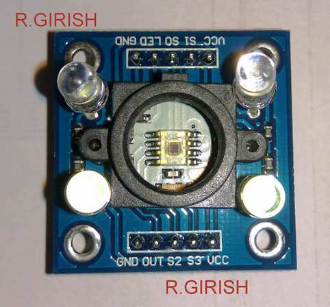
Illustration of TCS3200 sensor:

It has 4 built in white LEDs for illuminating the object. It has 10 pins; two Vcc and GND pins (use any two of these). The function of S0, S1, S2, S3, S4 and ‘out’ pin will be explained shortly.
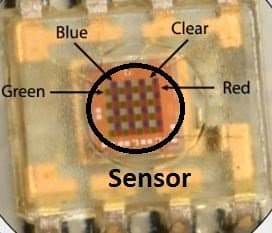
If take a close look at the sensor, we can see something as illustrated below:

It has 8 x 8 array of color sensor that’s total of 64. The photo-sensors block has Red, Blue, Green sensors. The different color sensors are formed by applying different color filters on the sensor. Out of 64, it has 16 blue, 16 green, 16 red sensors and there are 16 photo sensors without any color filter.
The blue color filter will allow only blue colored light to hit the sensor and reject the rest of the wavelengths (Colors); this is same for other two color sensors.
If you shine a blue light on a red filter or green filter, less intense light will pass through the green or red filters compare to blue filter. So the blue filtered sensor will receive more light compare to other two.
So, we can put the colour sensors with RGB filters in a block and shine any coloured light, and the relevant colour sensor will receive more light than other two.
By measuring the intensity of the light received at a sensor can reveal the colour the light shined.
To interface the signal from sensor to microcontroller is done with light intensity to frequency converter.
Circuit Block Diagram

The “out” pin is the output. The output pin’s frequency is 50% duty cycle. S2 and S3 pins are select lines for photo-sensor.
You understand better by looking the tabulation:

By applying low signals to pin S2 and S3 will select the red colour sensor and measure the intensity of red wavelength.
Similarly, follow the above tabulation for rest of the colors.
In general Red, blue and green sensors are measured leaving the sensors one without filters.
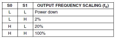
The S0 and S1 are the frequency scaling pins:

S0 and S1 are frequency scaling pins to scale the output frequency. The frequency scaling is used to select the optimum output frequency from sensor to the microcontroller. In case of Arduino 20% is recommended, S0 ‘HIGH’ and S1 ‘LOW’.
The output frequency goes high if the light intensity of the relevant sensor is high. For simplicity of the program code the frequency is not measured, but the pulse duration is measured, higher the frequency less the pulse duration.
So, the one which on the serial monitor readings shows the least has to be the color which is placed in front of sensor.
Extracting Data from the Color Sensor
Now let’s practically try and extract data from the sensor:

Program Code:
//--------------Program Developed by R.GIRISH--------------//
const int s0 = 4;
const int s1 = 5;
const int s2 = 6;
const int s3 = 7;
const int out = 8;
int frequency1 = 0;
int frequency2 = 0;
int frequency3 = 0;
int state = LOW;
int state1 = LOW;
int state2 = HIGH;
void setup()
{
Serial.begin(9600);
pinMode(s0, OUTPUT);
pinMode(s1, OUTPUT);
pinMode(s2, OUTPUT);
pinMode(s3, OUTPUT);
pinMode(out, INPUT);
//----Scaling Frequency 20%-----//
digitalWrite(s0, state2);
digitalWrite(s1, state1);
//-----------------------------//
}
void loop()
{
//-----Sensing RED colour-----//digitalWrite(s2, state1);
digitalWrite(s3, state1);
frequency1 = pulseIn(out, state);
Serial.print("RED = ");
Serial.print(frequency1);
Serial.print(" |");
delay(100);
//------Sensing Green colour----//
digitalWrite(s2, state2);
digitalWrite(s3, state2);
frequency2 = pulseIn(out, state);
Serial.print(" Green = ");
Serial.print(frequency2);
Serial.print(" |");
delay(100);
//------Sensing Blue colour----//
digitalWrite(s2, state1);
digitalWrite(s3, state2);
frequency3 = pulseIn(out, state);
Serial.print(" Blue = ");
Serial.println(frequency3);
delay(100);
Serial.println("---------------------------------------");
delay(400);
}
//--------------Program Developed by R.GIRISH--------------//
Serial monitor OUTPUT:

The reading one which shows the lowest is the colour placed in front of the sensor. You may also write code for recognizing any colour for example yellow. Yellow is the result of blending of green and red, so if yellow colour is placed in front of the sensor, you have to take the red and green sensor readings into consideration, similarly for any other colours.
If you have any questions regarding this RGB color sensor TCS3200 using Arduino article, please express in the comment section. You may receive a quick reply.
The above explained color sensor can be also used for triggering an external gadget though a relay for executing a desired operation.
yes the sensor may not be that efficient, this has been notified at the end of this subsequent article:
https://www.homemade-circuits.com/2017/09/relay-trigger-by-color-detection-using-arduino.html
Hi Farhan,
I will make a article explaining how relay(s) can be triggered with detection of a specific color, soon.
Regards
Now is it possible to make relay off by getting green color light ??
Mr. GR will answer your question soon…..