The operating principle of this children's night light is to gradually familiarize the child with darkness by gradually reducing the brightness of their bedside lamp.
The room's brightness will slowly fade away and completely extinguish after a duration ranging approximately between twenty minutes and 5 to 7 hours. This duration can be adjusted from week to week based on the child's progress.
How the Circuit Works
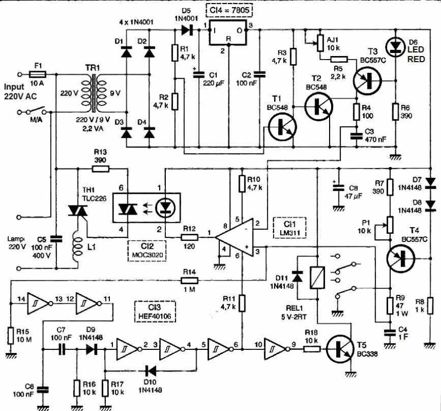
The diagram below presents the schematic diagram. The light dimming is achieved through a 100 Hz ramp generator synchronized with the mains frequency.

The slow discharge of a high-value capacitor allows for a gradual dimming of the light over an adjustable duration, covering a wide range of several hours.
A low-power transformer reduces the mains voltage and provides galvanic isolation between the power grid and the low-voltage power supply of the circuit.
The secondary winding produces an AC voltage of 50 Hz/9Vrms, which is rectified by a full-wave bridge rectifier composed of four diodes, D1 to D4, of type 1N400x (if your transformer has two secondary windings, only two diodes are sufficient for full-wave rectification).
Initially, this bridge is charged by the voltage divider R1/R2. Additionally, diode D5 charges the smoothing capacitor C1. The resulting DC voltage is then regulated by a classic 7805 voltage regulator stabilized by the decoupling capacitor C2. Light dimming
The resistor bridge R1/R2 biases transistor T1, with its collector loaded by resistor R3. This transistor conducts for most of an AC half-cycle, blocking the base-emitter junction of T2, which remains off.
However, on each transition of the AC half-cycle, the rectified voltage passes through what is commonly referred to as the zero-crossing point.
At this instant, the base of transistor T1 is at 0V, effectively blocking it. The base of T2 is then released, and resistor R3 saturates transistor T2, making it conductive.
During the duration of the zero-crossing period, the saturation of transistor T2 leads to the discharge of capacitor C3 through resistor R4.
The time constant of R4/C3 is significantly smaller than one AC half-cycle, resulting in nearly instantaneous discharge of capacitor C3.
This phase corresponds to the steep falling edge of a sawtooth waveform.
However, as soon as transistor T2 is blocked, capacitor C3 starts to charge at a constant current because transistor T3 is then biased as a current generator. The voltage across capacitor C3 evolves linearly.
Indeed, the potential of the base of transistor T3 is fixed by the forward voltage of LED D6. With the voltage across resistor R5 + Aj1 being constant, the collector current of transistor T3 remains constant (Ic ≈ IE).
The sawtooth signal resulting from the constant current charging of capacitor C3 is compared to a threshold, which depends on the level of charge of capacitor C4.
This high-value capacitor (1 Farad, equivalent to 1000 capacitors of 1000 uF) is also charged at an adjustable constant current using potentiometer P1.
The sawtooth signal is then compared by IC2 to a slowly increasing voltage threshold. The comparator IC2 is an LM311, and its output stage consists of an open-collector power transistor.
As long as the sawtooth waveform applied to pin 3 of IC2 has not reached the threshold determined by the charge level of capacitor C4, the triac Q1 remains non-conductive, and no voltage is applied to the lamp.
However, as soon as the sawtooth waveform exceeds the threshold set by C4, the triac is triggered and remains conductive for the remaining duration of the AC half-cycle.
The more capacitor C4 charges, the later the triac is triggered compared to the beginning of an AC half-cycle. As a result, the lamp becomes less and less bright.
IC8 is an optotriac that ensures the triggering of the triac and provides galvanic isolation between the 220V mains and the low-voltage control circuit.
The lamp's Shut Down
The end of capacitor C4's charging, which corresponds to the complete extinguishing of the lamp, is detected by a Schmitt trigger inverter. During the charging of capacitor C4, the output 11 of IC3 is in a logic state 0.
When the switching threshold of the Schmitt trigger at input 14 of IC3 is reached, output 11 changes to 1, and a positive pulse appears at the input of the memory consisting of diode D9, resistor R16, and the 1/2 and 3/4 inverters of IC3.
Capacitor C6 prevents the memory from being triggered during power-up. From now on, a low state is present at output 6 of IC3, which blocks the comparator IC2, preventing any triac switching.
At the same time, the base current of transistor T5 is removed, causing it to block. The relay is no longer powered, and capacitor C4 discharges through resistor R9, which is connected to ground by the relay's normally closed contact.
The same discharge process will occur if you disconnect the power to the circuit while the lamp is still on. In that case, you'll need to wait for a minute between turning the night light on and off to ensure that capacitor C4 is fully discharged.
Construction
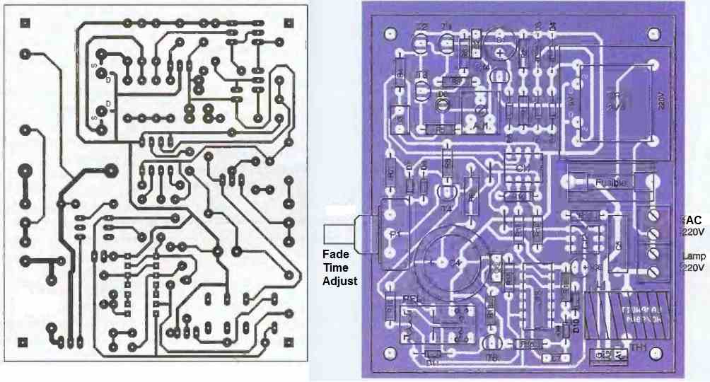
The layout of the tracks has been designed for the use of a 2.2VA transformer, both with a single and a double winding.

With a double winding transformer, only two diodes are sufficient for rectification, while a four-diode bridge rectifier (Graetz bridge) is necessary if the secondary winding is single.
The selection between the two models is made by appropriate solder bridges on the printed circuit board, at the level of the two central pads intended for the transformer's secondary winding.
For a double winding transformer, you will solder the tracks marked with a "D" to the secondary winding pins. In the case of a single winding, the tracks marked with an "S" will be soldered to the transformer pins.
The component placement above shows the two unnecessary diodes in the case of a double secondary winding.
The triac should be a model with a very low holding current because the bedside lamp is typically equipped with a low-power bulb, generally around 40W.
Generally, sensitive models with low current ratings (2 to 4A) are preferred. Also, choose an isolated model and provide a plastic protective cover for the fuse holder.
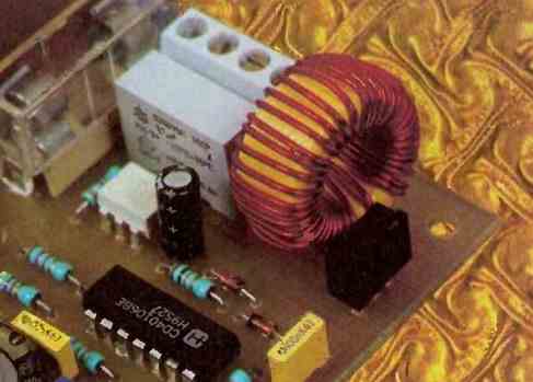
The self suppressor L1 inductor can be any 10 amp suppressor coil, as shown in the image below:

How to Setup
Set the slider of the adjustable resistor Aj1 to the middle position. As soon as the power is turned on, the lamp should light up. The only adjustment required is to control the slope of the sawtooth waveform, either using a multimeter or an oscilloscope.
With a digital multimeter on a 20VDC range, adjust Aj1 to read a voltage of 1.8V. With an oscilloscope, adjust Aj1 so that the peak of the sawtooth waveform is just slightly clipped.
The amplitude of the ramps will then be close to 3.5V. The potentiometer P1 is turned to the left to decrease the time required for lamp shut down and to the right to achieve the slowest progression.
Depending on the manufacturing of the 40106 IC, its switching threshold can vary from 2 to 3.6V. If you find that the maximum duration obtained with your prototype is insufficient, decrease the value of resistor R15.
The accompanying photograph shows the use of a 40106 IC from TEXAS Instruments, with its switching threshold raised by decreasing the value of R15 to 5.6 MΩ. The lamp's shut down then occurs after more than 7 hours!