The following article provides a simple yet very decent solution for driving powerful LEDs rated at 3 watt or 5 watt.
Circuit Objective
These 3 watt 5 watt and similar high watt LEDs are able to produce highly intense and powerful light outputs, however these are extremely vulnerable too with their operating parameter. I have explained more how to operate these devices very safely using a simple power supply.
We have seen quite many power supply and driver circuits in this blog using the IC LM338, that's because this particular device is so versatile with power regulation and control functions.
The same IC yet again takes the center stage in this application too. Here the IC LM338 has been configured in its standard mode and it perfectly executes the expected current as well as voltage regulations for driving a 3 watt or a 5 watt LED.
Circuit Operation
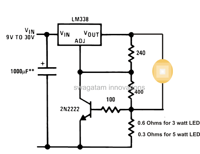
As shown in the circuit diagram below, in its standard mode the resistor 240 ohms is a regular placement, and the next resistor connected to it is the one which decides the voltage at the output of the IC. Here it has been calculated and set for producing around 3.3V at the output, which is the optimal voltage value for driving all types of white LEDs.
However the IC itself cannot control the current and normally would allow about 5 amp at the output.
We can see that the IC is associated with an additional active component which is the transistor connected to its ADJ pin.
The transistor here is employed solely for controlling the current at the output to the specified limits.
The resistor across ground and base decides how much current would be allowed to the output.
As indicated in the diagram, 0.6 ohms will pass about 1 amp maximum current which becomes suitable for driving a 3 watt led safely, and if a 5 watt LED needs to be driven safely, this resistor must be replaced with a 0.3 Ohms, which will allow a maximum of 2 amps of current.
The input to the IC can be derived from a standard transformer bridge capacitor power supply or from a suitably rated battery supply.

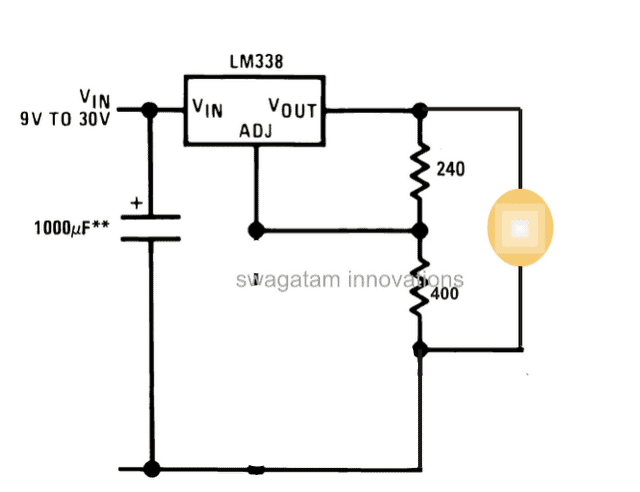
In fact, the transistor and the associated base/emitter resistors are absolutely not required, because once the voltage is set to precise 3.3V, the current would automatically get adjusted as per the LEDs specs.
So the correct circuit should be as given below:

Update:
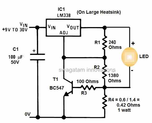
The above suggestion is not recommended if the ambient temperature is above 25 degrees Celsius. Therefore users are requested to go with the first universal design using the BC547 as the current limiter stage, for enabling the intended current control function.
LED Driver Request
The following request for a customized 9 watt LED driver with constant current was requested by one of the avid readers of this blog
We need constant current LED driver. Supply in put is 11.0 vTO 15.0 vdcOut put required is constant current 1400 mA, 8.4VDC. The Load is 3 White Power LEDs, having Vf - 2..7 to 2.8V. This cluster will operate in flashing (Blinking mode). The circuit should have utmost high reliability, minimal number of components. We were using ONSEMI Linear LED Driver NSI 50350AST3G, (qty. 4 nos. connected in parallel)which is now not available Can you please suggest us some suitable Part or Circuit?
The following circuit diagram was suggested for the above application:
