In this article I have explained a 32V, 3 amp SMPS circuit which may be specifically used as an SMPS 100 watt LED driver, rated with the same specs.
The circuit of the proposed 32 V, 3 amp smps led driver may be understood with the the help of the following points:
Circuit Operation
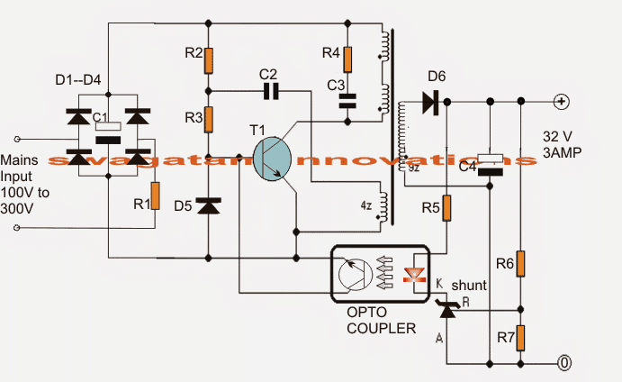
The mains voltage is rectified and filtered by the bridge network and the associated filter capacitor C1. This rectified 310 V DC passes through R1, R2 and triggers T1 into conduction.
T1 switches ON and pulls this DC to ground through the 30 + 30 primary winding inducing a steep pulse through this winding and also across the lower auxiliary winding.
This pulse across the auxiliary winding enables a negative pulse to be generated at the junction of R1/R2 which momentarily sinks the base drive to ground such that T1 now shuts off.
In the meantime C2 charges up drying up the auxiliary winding impact, and allows T1 with a fresh triggering potential at its base.
T1 conducts yet again and the cycle keeps repeating at a frequency determined by the value of R2/R3/C2 which could be around 60 kHz here.
This rapid switching induces a corresponding voltage and current across the secondary winding which may be well over 32 V, 3amps AC as per the given winding details.
The above voltage is appropriately filtered by C4 and applied across R6, R7 for feeding the shunt regulator and the opto coupler stage.
R6 is appropriately adjusted such that the output voltage settles to about 32 V.
The Shunt Regulator
The shunt regulator instantly activates the opto in case the voltage tends to rise above the set value.
The opto in turn "kills" the base drive of T1 temporarily disabling the primary operations until the output potential is restored to the correct value, the opto now releases T1 and allows the operations to work normally, only until the output rises again to initiate the opto yet again, the process keeps repeating ensuring a constant 32 V at the output, for driving the 100 watt LED module safely
Circuit Diagram of 32V 3A LED Driver for 100 Watt LED

The transformer is wound over a standard EE ferrite core having a central cross sectional area of at least 7 square mm.
Referring to the figure, the upper two primary winding are made up 30 turns of 0.3 mm diameter super enameled copper wire.
How to Wind the Ferrite Transformer
The lower primary auxiliary primary winding consists of 4 turns of the same wire as above.
The secondary is wound with 22 turns of 0.6mm super enameled copper wire.
The procedures are as follows:
- First begin winding the upper 30 turns, secure its ends on the bobbin leads by soldering, and put a thick layer of insulation tape over these turns.
- Next, wind the secondary 22 turns and solder its end terminals on the other side of the bobbin leads, put a layer of thick insulation tape.
- Over the above layer start winding the auxiliary 4 turns and as above secure the ends appropriately on the primary side leads of the bobbin, again put some layers of insulation over this,
- Finally, wind the second 30 primary turns starting from the previous 30 turn end, and secure the end over one of the leads of the bobbin on the primary side.
- Cover the finished winding with additional layers of insulation tapes.
- Make sure you remember the terminated leads properly so that you don't make incorrect connections with the circuit and cause a possible fire hazard.
Parts List
All 1 watt, CFR
- R1 = 10E
- R2 = 1M
- R3 = 470E
- R4 = 100E
All 1/4 watt MFR 5%
- R5 = 470E
- R6 = preset 22k
- R7 = 2k2
- C1 = 10uF/400V
- C2 = 2.2nF/250V
- C3 = 220pF/1kV
- C4 = 2200uF/50V
- D1---D4 = 1N4007
- D5, D6 = BA159
- shunt regulator = TL431
- opto = 4n35
- T1 = MJE13005
sir, do you have any youtube account about your project?? if you have, please share the link of your channel.
Hello Shamim, I do not have a youtube video for the above concept.
What must be modified,if you want a voltage output of 50 volt and a current of 6 Ampere.
Tank you.
For the voltage adjustment, first disconnect the collector of the opto-coupler transistor from the base of the T1, and check the output voltage. If it is above 50V then no need to change anything in the secondary winding. Now reconnect the collector of the opto transistor with the base of T1 and adjust the values of the R6 and R7 until you get a fixed 50V.
If it is less than 50V, then you have to increase the secondary winding and repeat the above procedures.
For increasing current, you may have to increase the wire thickness of both the sides windings.
at the output 3 amp how can we use BA159 its 1amp diode
Yes that’s right, please change it to a 5 amp schottky diode.
sir you have not defined the primary inductance of transformer
Hello Sanjay,
Inductance value is not known to me, and I think it is not required since the winding specifications are given in details.
Hello swagatam pls help me .I built this smps circuit but it doesn’t work am not getting any voltage at the output of the transformer and secondly I used 13003 transistor instead of 13005 due to unavailability but it didn’t work so I now changed the 13003 to 13001 transistor which it blew up again i don’t no why but pls help me asap……..
Hello Okongwu,
the person who contributed me this article has tested this design successfully.
However, please remember that the heart of any SMPS is its transformer. If you make even a smallest of mistakes in the transformer winding then it may have serious consequences or it may simply not work.
I would suggest that initially you keep the opto feedback cut off or removed from the circuit and test just the basic response.
Make sure to provide a paper gap between the E core legs where the two e cores join with each other.
Always use a 40 or 60 watt bulb in series with the 220V mains while testing an smps circuit.
Dear swagatam I used an EE16 FERRITE core transformer with no air gap ,and what is the importance of an air gap in a FERRITE transformer. And pls can I have your WhatsApp number I wish to learn more from you
Thank you…….
Hi Miracle,
Air gap or paper gap prevent the transformer core from getting saturated which can otherwise result in short circuiting of the switching transistor.
You can communicate with me through this blog comment platform since I am mostly online with my blog. You can ask as many questions as you want, I will try to help.
Hello swagatam how can I reduce the voltage of this circuit to 4.2v in order for me to charge a lithuim ion battery???
Hello Okongwu,
For 4.2V you can try the concept explained in the following article:
https://www.homemade-circuits.com/220v-smps-cell-phone-charger-circuit/
Swagatam, good afternoon.
I am an industrial automation engineer.
I am doing such a project, it is for people with low incomes.
https://www.facebook.com/dan.saudabaev/posts/pfbid02nT1yLhhQ4kspxVPupVZtntpHeiCMfnLPmBa5KoxWeu2QJ6gn8Gmk7bqbDXFtiFkjl
I bought samples of lamps on Sanan & Seuol diodes, spectrum 5000k+660nm (for leafy greens) – lamps 24V/40W (1.66A).
We sell regular switching power supplies
POWER SUPPLY 24V 20A 480W ($16).
There is no 36V.
I want to connect DC-DC converters (XL4016) to it.
It has two resistors for voltage and current.
– stabilization in both current and voltage (right?)!!!
Set the output to 24V, reduce the current for the lamps by 5% (1.58A).
And connect the lamps in parallel.
Sir, reducing the current by 5% will give me a guarantee that all the lamps will work without any problem?
In the description –
10. For example: input 12V * 5A = 60W, input 24V * 5A = 120W
Input 36V * 5A = 180W, input 48V * 5A = 240W
Sir, approximately how many watts can this DC-DC converter produce?
Efficiency, if 4-5A will be higher than 90%?
Another option is a DC-DC converter:
I asked them questions in the morning, they promised to answer, but there is still no answer. There are few specialists there… – they can’t even answer basic questions!
Thank you Dan,
If the current limiting is set to provide 1.58A then the LED lamps cannot get more than this value. So if the requirement for your parallel LED lamps is more than 1.58A then their light intensity will become reduced and they will look dim.
Swagatam, hi.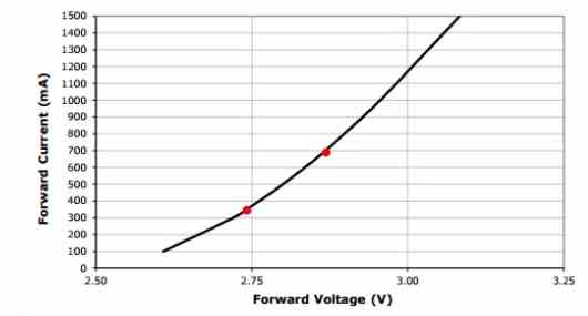
You’re right –
" rel="ugc">
You can see this clearly from the electrical characteristics of the Cree XP-G2 below in Figure 1. When the LED is turned on, even the smallest 5% change in voltage (2.74V to 2.87V) can create a 100% increase in current driven to the XP-G2 as you can see at the red marks current went from 350mA to 700mA.
– I’m very surprised that a minor change can have such an impact!!!
Thank you)))
Thanks Dan,
Yes i agree.
As the voltage nears the LED’s maximum forward drop level, the current tends to increase drasitically. That is why it is crucial to have a constant voltage supply which can never exceed the forward drop level of the LED.
– constant voltage driver?
Sorry to interrupt you…
But if the external voltage jumps, and the driver output has a stabilized voltage
– then the current will change, which will have a very negative impact on the diodes!!!
I chose the fixed current driver DL-400W-V260X-PLS
Input voltage 120-277V.
They told me that they could use a programmer to fix the current I needed (1.66A).
And I want to connect 8 lamps in series (24VDC, 40W, 1.66A).
– Am I doing it wrong!???
Dan,
With a consant voltage regulator the voltage to the LED can never jump, unless the input AC becomes exceedingly high, which would anyway destroy all forms of stabiliziing elements.
If the DC voltage is fixed or constant then current becomes immaterial, meaning larger current will have no impact on the LED. For example if you supply a 3.3 V to a 3.3 V LED, with a current of a million amps, the LED would still illumnate safely and draw only the amount of current it needs optimally at 3.3V.
Conversely, if you have a fixed or a constant current then the voltage becomes immaterial, meaning suppose if you have a current limit applied to a 3.3V LED, then even if the volatge increases to 100V or 1000V it would drop down to 3.3V without harming the LED.
If you are too much concerned then you can have both constant current and constant voltage supply for your LEDs.
Sir, excuse me, one more question.
Where I ordered samples of lamps, a girl works there as an engineer.
They agree to check the connection of 8 lamps to this driver.
But she claims that they have constant voltage lamps (24VDC, 40W) and this driver will not work.
I explained to her that there is no such thing as constant voltage or constant current lamps.
I asked for a wiring diagram for the diodes, but for the second day it was silent.
I gave them a diagram of how to check –
https://photos.google.com/photo/AF1QipNMR479Lv7Msybv3Nj5RwHU9G9kY520JSYeVax5
Using Variac Auto Transformer we change the input alternating voltage 150-250V, using multimeter 2 we look at the variable voltage, using multimeter 1 we look at the fixed current (1.66A).
I don’t know how else to explain to them))))
Maybe you can help?
Dan, You can show me the picture link of the lamp, I will try to figure out its specifications.
The link of your google photos is not opening in my computer.
Sir, sorry, I’ve been working all day.
I made the link wrong.
https://photos.app.goo.gl/ChLTCjH344kk6yzM8
Hi Dan, THe voltmeter and the ammmeter connections are correcty wired. No problems.
Good morning sir.
https://photos.app.goo.gl/KsTvj643rAYi2K1s9
– this is the programmer they have.
That link is not working.
Sorry, I did not understand what you mean by programmer? I actually asked about the LED specification which you are having problem with.
Programmer – I’m talking about the capabilities of this company that produces drivers.
https://drive.google.com/file/d/1s5KFJelMUinbIDeyOztnIIc3_tKuxfMO/view?usp=drive_link – just received.
– diode connection diagram.
They made me two samples using diodes:
– SANAN MH-S3030E23C50HE " rel="ugc">
– SEOUL 3030C.
They claim that voltage drivers are needed for these lamps.
Are there diode circuits for voltage or current?
Your first googlr dive link needs to be in the shared mode otherwise it won’t open for me.
You can see in the second link, all the specifications of the LEDs are given.
You simply need a constant voltage and a constant current LED circuit adjusted to the above specifications, that’s all, and the LED will be safely driven. Ofcourse if the LED heat up a bit then you might require a heatsink also.
Good afternoon sir.
Sorry, I’ll repeat it again.
The company that produces the lamps claims that their lamps are for voltage drivers.
I sent you their lamp wiring diagram, there are 276 diodes.
They have 10 sections (each with 27 diodes), I think there is such a connection – https://drive.google.com/file/d/1N1w1mSncy970dPmukWq9ivNcBqu1UG08/view
Swagatam, these lamps, if you connect them 8 in series – https://photos.app.goo.gl/ChLTCjH344kk6yzM8
– will they work under a current driver?
I have no doubt that these lamps will work under both a current driver and a voltage driver – there is no difference there!!
Hi Dan, Your Google drive link is not opening because you have not sent it in shared mode.
Yes, LEDs in series will work with constant current driver circuit.
Using a constant voltage and a constant current driver is the best option.
https://photos.app.goo.gl/WXpbqmcuN3fisnFt7
– opens?
They have 276 diodes on the lamp.
I took one sector (there are 10 in total).
There are 27 diodes in this sector.
If we take an operating current of 65 mA, then the result is a current of 195 mA in three parallel circuits.
If there are 10 sectors, then the total is 1.95A.
However, they state that the lamp is 24V and 1.66A.
Are they wrong or am I wrong?
Yes the image opens now.
Your calculations are perfectly correct.
Did you ask them the reason why they state it should be 1.66 amps?
It maybe because they want to reduce stress on the LEDs to enhance their life.
By the way if 65 mA is the maximum breakdown current of these LEDs then it may be recommended to use a current that’s below 65 mA
Thank you sir ))))
As an LED lighting specialist, you helped me a lot!!!
You are most welcome Dan, Glad I could help!
Hi, have you got PCB project for this power supply?
Hi, sorry, a PCB is not available for this project!
Sorry Swagatam, I forgot to ask
– what is the efficiency of these SMPS drivers?
Efficiency could be around 80 to 90%
I need some advice.
Sir, please help.
alibaba.com/product-detail/Exclusive-Design-Against-Moisture-And-Dust_1600724917607.html?spm=a2700.details.0.0.52ac6e5b3ohgnl
– it says here – 100W 200W 300W 400W Smps Dc12v 24V Constant Voltage LED Pulse.
Does this LED driver have stable constant current?
I’m a little confused by what it says – constant tension!
Thank you very much sir!
Hi Dan, if the unit is specified for operating power LEDs then it should be current controlled, however since no specific mentions are made it is always better to inquire about the same from the manufacturer before purchasing it.
Thank you very much, sir)))
You are welcome Dan!
I have made this circuit but it is giving 24v in open circuit condition and 11v when load is connected. As it crosses 11v, MJE13005 is getting short circuit and R1 is getting burnt. Can anyone help me?
Adjust the R6 R7 resistors to increase or decrease the output voltage. If the transformer is not built correctly then the transistor will burn. Make sure to add a paper gap between the E core legs.
All SMPS circuits published in this blog are strictly recommended only for the experts who are well versed with electronic switching circuits.
Few observations:
1) 7mm^2 looks like suspiciously small value for 100W something. Especially flyback.
2) Its much better to use versions of RCC flybacks that employ current-sense resistor and transistor that closes main switch upon reaching current limit. Without current sense this thing would blow up badly upon e.g. short circuit in secondary due to lack of protections limiting outup power. Current sense resistor hooked to small BJT closing main one – and once voltage exceeding about 0.6V it would initiate shutdown of main transistor. Net result is that current in primary winding limited to whatever value causing 0.6V drop on resistor (so value of current sense resistor sets available output power) and wouldnt exceed that, not even on output short circuit – actually that’s what makes flybacks quite robust things.
How to calculate RC time constant ?
Auxiliary winding has 4 turns , how much voltage will be induced to secondary winding ?
You can search it online, you will get the formula from wikipedia.
Auxiliary winding is only for switching the transistor base….the actual voltage induction happens across the upper primary winding and the secondary winding…the secondary winding will produce over 50 V.
Sir, What is the role of Diode D5 ??
R2 = 1M, R3 ~= 0.5K (suppose voltage Across C1 is 315 V).
Using these values
Total Voltage across (R3+ D5) : = 0.857 (0.157 Volt Across R3 + 0.7 Across D5 )
To conduct the Transistor ?
Sanjay, D5 is for neutralizing any residual negative spikes that may arise from the high frequency oscillation.
Total voltage across D5 will 315 V but due to extremely low current it will drop to the transistor’s base/emitter forward voltage 0.7 V enabling a forward bias for the transistor base.
Hello sir what would be the typical value of transformer in order to purchase it.
Hello Rohit, the transformer shown in the above diagram is not available ready made….you can either build it at home, or get it made-to-order from a professional coil manufacturer
Swagatam sir,
What changes are needed in design for 12V 3A and how much the new circuit may cost approx.
Thanks in advance.
Shivraj, for 12V 3 amp you can use the following circuit:
https://www.homemade-circuits.com/12v-5-amp-transformerless-battery/
I am not sure about the cost of the circuit.
Thank you sir.
Please explain how can I increase or decrease the frequency. Is there any Calculation ??
I have a EE ferrite core of approx 50watts transformer. I just need 12V 3Amp output can I use 26 or 27 or 28 any of the AWG wire in primary of about 30+30 turns ??
Also suggest can I use D4903 Transistors in primary side for switching ??
You should do exactly as suggested in the diagram, no other changes is recommended.
Pl explain about windings which is counter colck wise?
There are no counter clockwise winding, all winding are in the same direction.
So much thanx ,sir.
You are welcome!
Using the above circuit diagram and assume a constant input voltage of 230 Vrms. Please could you tell us how to calculate the switching frequency using R2 as 1 Meg ohm , R3 =470 ohms and C=2.2nf. Thank you beforehand.
bobinlerin kaç tur sarılacağını devre şeması üzerinde gösterebilirmisiniz.teşekkür ederim
for 42v and 5A I would like to know what changes I have to make.
You can adjust the values of R6, R7 suitably to get 42 V at the output
Hello Please specify how many turns the transformer will draw and determine the wire cross section by drawing the shape and schematic.
Please sir I really need to know fully about the transistor switching off process. What process is involved in the transistor switching off?
When AC is switched ON, the transistor conducts through R2, R3, and pulls the upper winding to ground. This induces a negative pulse on the lower auxiliary winding. This negative pulses passes through C2 and cancels the base bias of the transistor and switches it OFF. When transistor switches OFF, the upper winding is restored to its original situation, and cycle continues rapidly.
Ok thanks.
That’s you mean, the voltage induced in the feedback winding is in opposite polarity, and that reverse bias the base to emitter junction…
Is this situation different from some circuit that implies that the transistor has to be saturated at some point, because of the positive regenerative feedback from the auxiliary winding?
And also, please can you explain further how the RC circuit helps in setting the switching frequency?
The RC components at the transistor base decides how fast the transistor is switched OFF or how long the transistor remains switched ON. This determines the frequency.
How RC Circuits Work
Ok thanks a lot.
But what about the first question, still about how the transistor switching off.
[That’s you mean, the voltage induced in the feedback winding is in opposite polarity, and that reverse bias the base to emitter junction…
Is this situation different from some circuit that implies that the] transistor has to be saturated at some point, because of the positive regenerative feedback from the auxiliary winding?
It will be difficult for me to comment on other explanations until I see the schematic. But for the above concept it seems the auxiliary winding is responsible for the switching off job of the transistor base.
Dear Swagatam
I made the circuit as per schematic with the components listed along. Tested it on 230v-50Hz with a 100w bulb in series to limit over current draw due to any fault in the circuit. Results are as below:
1. 100w series bulb didn’t glow , got 15v out put with a load of output indicating LED. (3mm LED with 3k series resistor.
2. Output voltage can be adjusted with R6 (pre-set) from 10v – 22v.
3. Adjusted the voltage at 12v and connected an auto lamp of 12v-21w.
4. As soon as above lamp was connected, indicating LED went off and after disconnecting the lamp LED came on.
5. The SMPS is designed 100w output but it shuts at 21w.
6. I am unable to diagnose the fault and need your guidance.
Thanks dear A.M., appreciate your efforts and experiments with the above project.
I think you should check the wattage with a 33 V load, that will give you a better idea regarding the wattage rating of the circuit.
You can try increasing the value of C2 slightly and check if that helps to increase the current output of the smps.
You can also try experimenting with R3, and see how the output responds.
I also tried this but on very low load tere is no problem but as soon as I increase the load it seems everything gets off and as soon as load is removed everything again starts working
Hello again,
Is it possible to reach the amperage of this circuit to 10A or more just by increasing secondary wire diameter? Or need to replace other components too?
Hi, yes that may be possible by using many thin wires in parallel instead of a single thick wire. Only the MOSFET will need to be considered and matched with the specified current output
Thanks and how can I turn -50,0,50 to 0,100v?
you can remove the center tap wire from the secondary….
Sorry to ask too many questionz today.
Can i use IRFP460(500V,20A) or IRFP450(500V,14A) instead of MJE13005?
I have also MJE13007, is it working instead?
A MOSFeT might work, but since a MOSFET requires around 10V to work optimally while a BJT requires just around 1 V so the R2, R3, C2 might need some change accordingly
Hello Swagatam,
I hope you are well.
There are alot of circuits or designs which give us 12 to 50 vdc without transformers.
What are the reliable solutions for above 100v and less than 200v dc? I mean high amperage current without transformer.
Clearly recently i have alot of issues to reach 100vdc that can bear more than 10Amp.
Thanks
Would you please guide me?
Hello Mah, the only recommended way of achieving your requirement is through an SMPS circuit, any other method can be either dangerous or highly inefficient.
So then it is normal to get 100vdc, 10Amp through SMPS.
Can you refer me to a circuit or one that could be modified to achieve 100vdc, 10Amp or higher?
Is it attainable from the subject circuit(32v,3A) by some components replacement?
Thanks
yes any desired output can b achieved using an smps within a valid workable range, the following is an example which could be perhaps modified appropriately for getting 100 V 10 amps
https://www.homemade-circuits.com/smps-2-x-50v-350w-circuit-for-audio/
Hi Swagatam
This circuit is practically capable of handling load up to 100w right??
And when the circuit is not loaded it will function ok right??
Hi Shuvam, yes it will do the mentioned tasks.
Hi Swagatam
Can I use 10n60c instead of mje13005???
Hi Shuvam, is the transistor rated at 400 V, 3 amp? If yes then you can use it….
Hi Swagatam
I have made the circuit but this is the 2nd time when the MJE13005 transistor got fried without any load what could be the reason ??
Hi Shuvam, it is a tested design, so it can be difficult for me to judge your circuit problem…the transformer is the key here, a slightest bit of inaccuracy in the winding or core assembly can create short circuit and burn the transistor.
Hi Swagatam
the octocupler is of 6 pins so what should i do
Should keep the Base and NC pin open
Hi Shuvam, please check the datasheet of the opto coupler, you will understand how the pins need to be connected.
Hi Swagatam
Instead of 32v 3amp if I need 20v 5 amp then what are the changes I need to make??
Hi Shuvam, you can adjust the output voltage by appropriately adjusting the values of R6, R7.
R2=1M
That is 1ohm right??
It’s 1 Meg Ohm
Hi Swagatam
Can you give me the ferriet core geometry information like what is it’s size vertically horizontally
Hi Shuvam, it is a normal EE core transformer, the dimension is given in the article.
Why C2 not charged through R2 with 310 VDC?
Hello Sir,
I would like to attend 50-100 khz circuits, I want to know should I remove D6 diode?
I need this generator for making Plasma devices which work in RF frequency.
Out put information:
30v- 60 Khz- 1 A
I am looking forward to hearing your comments.
Hello Shayan, D6 can remain as it is, but you must remove C4 for getting a the required frequency output
Thank you Swagatam,
I want to add another ferrit transformer that produce 5kv (1:15) and connect out put with ressitor for producing Plasma discharge! Do you think this circuit can sustain this pressure? probably it needs 4 amper currency!
Hi Shayan, this circuit cannot sustain 5kv load, unless the 5kv transformer is switched through a separate high power IGBTs
Transformer 7 square mm for 100W?It is i think small for this power.Can we use ferrite ring instead EE core?Witch square area off this ring?
Sorry, no ideas about it, I do not have the necessary details about ferrite ring core calculations.
D6 BA 159 for 3A?
It can withstand 20 A in pulsed form, but if you are not sure, please change it to a higher rated Schottky diode
Good Morning sir.. the transformer used on this has a gap or not?? Or there is a specific inductance value ???
Good Morning Hui, yes gap will be there! use paper or cello tape for the gap!
i already made this circuit and it works..i used the trafo with spec : np bout 600uH -700uH , the turns about 60Turns (just my , and ns about 242uH (22Turns).. for aux nAux 4Turns , the output voltage came out about 32VDC .. but the input from main still serial with lamp to avoid short circuit if my circuit did wrong.. what the little problem of my circuit is .. the Transistor came hot even no load on the output.. i already checked the input from main within serial with lamp just 1.5W only.. but why my Transistor become hot.. ??? thx before…
Hello, are you sure it’s only 1.5 watt at the input? At 1.5 watt the transistor should not become hot.
Please measure the frequency at the collector of the transistor…if it’s above 20 kHz then your is working OK, otherwise there may be some fault.
Yes.. i measure through watt meter .. but that is serial lamp as a fuse to avoid problem when my circuit did wrong.. so i serial the input to main with lamp.. the voltage is about 32vdc at the output of transformer.. i also check the freq with oscilloscope on the output.. measured the wave is like a block of wave and next block of wave has delay.. one block of wave contain many wave ..the freq i ve measured is about 275kHz …
When i add the component R 100 and C 331 on the primer transformer. The freq decrease to 250KHz .. but still high.. and wave is not block again..but contiNuos .. how to lower the freq , sir???
Hui, 250kHz looks very high. The frequency is decided by R2/C2. Please try increasing the value of C2 to 10nF an check the response!
when i directly give the input to the main.. the Transistor got destructed and little sound cracked of it.. o my God .. haha.. did i do something wrong..?? thats conditions was the capacitor 2.2nF/250V i have changed to 10nF/400V … might be my transformer went wrong of its np side .. on the input , i didnt use the R 10Ohm …
Yes the transformer is the main element here, and a wrongly optimized transformer may cause a lot of problems. Did you follow the winding procedure as explained in the article??
Hi Swagatam,
I came across your website by accident and all the DIY Circuits you put out to help Electronic’s Enthusiasts. Sadly I have to tell you that in two of your circuits which are Flyback derived, What you call the Transformer is not the correct approach. The Flyback, you could say is a Coupled Choke/Transformer.
In a Flyback, Energy is stored in the Primary Choke during the ON Cycle and then dumped in the Scondary in the Flyback mode in the next half cycle. However, Energy can only be stored in a GAP !!! Your transformer and design do not mention a Gap and that is where the design falls down.
The Output Power of a Flyback is given by the expression— Pout = 1 / 2.L I.pk^2.Fswitching, For L then and it’s inductance value , you have to define a Core with an Al with the relevant Air Gap value and reduced u. This would normally be in a Torriod ( Micrometals / Arnold / Magnetics ) or , any other Core Shape which is matched with a Gap Pre-Ground in the Centre Leg. After a design, there are some test Equations and results which have to be applied to see if the Gap and Core chosen is the correct one or if it should be changed.
If you would send me your Email address or any Email address then I will write up a Transformer design for a Flyback Transformer / Choke. Or also to design any Choke. I am happy to help but you must make it easy for me to do so.
I am 81yrs old, I have only worked in the Military Field on all sorts of Weapon Systems , Power Supplies and Hi Voltage Power Supplies for Travelling Wave tubes for Jammers and Radars. I had my own R&D Group and have taught many Engineers and Technicians in Magnetics which is regarded as a BLACK ART an d is not well understood and applied. I have also designed Pulse Transformers for a 5MW Peak Pulse Transmitter Mgnetron Driven. Also the present Saab Gripen Fighter has Two Power Supplies of mine.
Anyway I am prepared to help, you must provide the avenue to do so because I cannot copy and paste to this comment block.
Cheers, hoping to hear from you.
Regards
Dave Rundlett
Thank you Dave, I am glad to have you in my website and I am thankful to you for your valuable suggestions.
Yes I am aware how a flyback circuit is supposed to work, however most of the SMPS designs presented in this blog were not designed by me, rather referred from other sites. But strangely those sites have actually proved through images and videos that their circuits were actually tested.
Can you please tell me which are those two circuits which you think are not correctly optimized to function?
It will be an honor for us to learn from you, therefore I would request to please help my site to get better with your expert insights.
My email ID is homemadecircuits @ gmail.com
Saab Gripen is a single engine Swedish fighter plane which India wanted to acquire from Sweden but later on the deal was cancelled because we found a more comprehensive fighter plane in the form of Rafale, which is a more powerful twin engine jet.
I am amazed to know that you have worked with such a modern and magnificent aircraft, and you have your circuits running in this type of advanced fighter planes. It requires a huge amount expertise to get a unit approved for such state-of-the-art machines, we appreciate and congratulate you for this.
Hoping to hear more from you and learn more about the so called “BLACK ART” because I am sure there’s something too good hidden within these concepts that our governments want to be secretive about.
See you soon, and wish you all the best!
sir i want 14 volt output can u tell me modification need in the circuit
the easiest way is to reduce the secondary turn number until the 14V is achieved…
Sir,
I also assembled the circuit well but the 10ohm resistor bevome hot a d seriel bulb is lighting showing clear short
Please help
Sisin, the transformer winding is the crucial part, a slightest mistake will burn the circuit, so make sure it is done correctly along with the other connections….
thank you sir
i have the components ready and going to try this project
big fan
thanks
sure Hari, I hope you will be able to implement the design successfully, wish you all the best.
Realicé su circuito, tripliqué la cantidad de espiras al secundario porque necesito 90Vdc (1A). Así que alimenté con 220Vac, pero luego de la R1 cae a 56Vac por lo que la quité y decidí alimentar con 110Vac sin R1. Obtuve 165Vdc luego del filtrado principal, pero a la salida de la fuente no hay tensión, tampoco en el Vref del TL431, que puede estar mal?
Gracias
sir can you please explain the operating frequency design
Hi Hari, I do not have the calculation details for this design because it is a feedback based design and the frequency will basically depend on the values of R1/R2/C2 and the auxiliary winding specifications along with the input voltage value…the above design is a tested one so you just have to build it exactly as advised in the article for getting the results.
19V can be achieved by tweaking the secondary side parameters, and the current can bereduced by using a proportionately reduced wire thickness on the secondary winding
sorry it's R2/R3, and not R1/R2 as wrongly mentioned above…
sir
can i use this circuit for monitor power supply 19v 1.5 amps .
Is the transformer wound based on ordinary transformer coil equation??
sir i need to contact you as soon as possible … i have some doubts can u reply with u r gmail account I'll msg u over there
Vinay, you can feel free to express your thoughts here through your comments, I'll try to help
When I am trying the above circuit I am not getting any output voltage and instead 10 ohm resister (1W) which is burning in seconds and when I am using 2.2K ohm resister (2W) instead of 10ohm it is holding for 5 to 10 seconds and burning. What ever circuit I connect Resistor is burning out and no out put is coming and I tested the circuit with out connecting transformer to make sure mistake not in transformer even though resister is burning. Where is mistake, I need circuit up to 15W and not up to 96W so can you help me?
I cannot troubleshot your circuit from here.
If your input resistor is burning that clearly indicates that you have something seriously wrong in your circuit….the input 10 ohms will burn only when if the transformer and the transistor fails to oscillate and results in a short circuit.
and without the transformer how can the 10 ohm get the current to burn???…the circuit can never complete without the transformer.
Please check everything again, and do it only if you are sure regarding the working of the circuit.
read all the comments above for the hints.
How to reduce the voltage or current of the circuit to work it out more like 10 or 20 watt LEDs.
Can we do by reducing winding count in secondary or any capacitor capacitance.
I have explained the process in these articles, you may implement the same for the above idea too:
https://www.homemade-circuits.com/2015/04/how-to-make-variable-smps-driver-circuit.html
https://www.homemade-circuits.com/2012/11/how-to-modify-smps-circuit.html
….and this one too
https://www.homemade-circuits.com/2015/04/how-to-make-variable-current-smps.html
HEllo dear,
is it possible to get 12v output from the above circuit. just by reducing the number of turns in secondary winding.
or any more modification is required for the component values ?
hello chandan, yes that's possible by modifying the secondary winding, you can also try adjusting R6/R7 additionally for adjusting the required output….
Update. Tried the circuit and after some effort managed to get it to work. Worked on breadboard and the circuit seems stable and no transistors fried but i used BUT11 which is a workhorse transistor that can stand 1000V. Does not show signs of instability even with no load. For more protection for possible voltage spikes i used a 400v TVS transient supressor diode Between the two primary windings.
I measuered 150khz frequency on transistor base that seems a lot more than the frequency you mentione on but i suppose that multimeters measurument is not accurate and i dont have an oscilloscope to see the exact base drive.
You were correct about the ferrite crack issue. Didnt manage to get more 24watts from it, but i manage to get a stable 0.8A 24V output. Just 20-30 higher than 0,8A caused the output voltage to sink to 18V and more.
Anyway the circuit is usefull if you try to study flyback topologies. Using a But11 transistor will be an improvement and give you the confidence to try to alter the frequency till you get the maximum efficiency/output from your core especially since the cores we hobbyists use, are pulled ones and have no markings so we cant find a datasheet for them nor do we know what material they are made from.
Mr swagatam i want to make you a question. From my experience on the secondary output regulating topologies when using zeners and optocoupler there are two different topologies. The first uses the zener directly on + output after schotkey diode, a resistor 100-470ohms in series connecting it to the positive leg of the optocoupler and the second leg of the optocoypler is grounded. But there is another topology that between the positive leg of the optocoupler is just the 100-470ohm resistor and the zener connects between the negative optocoupler leg and ground. Which of the two is the best and what are their main differences?
Thank you
Thanks very much S3NSIT for the update, this will be extremely useful for all the readers intersted in building this project.
both the opto topologies are good and is meant for creating a regulating feedback from secondary to the primary, the only crucial thing is the resistors and the zeners which must be correctly calculated in both the types for ensuring a proper and safe regulation of the output voltage
in this circuit we get ac output 32 volt or
DC? sir
It is DC, after the diode D6
Sir thank you for this smps. I have a soldering iron 24V 60W and i would like to use your design to power it. I could buy an 220/24dc easily but for the joy of DIY i would like to make my power supply (soldering iron heat control is DIY by me with arduino).
Except adjusting the TL431 shunt regulator to 24V what transformation should be done to secondary winding to receive 24V dC output? Maby using 16 turns instead of 22?
i also want to ask your opinion about my ferrite which is an E one salvage from a VIDEO SMPS supply. I heat with a heat gun but when trying to disassemble one of the two ''Es'' cracked but i managed to fix it with super glue perfectly and now you cant even see the gap. Will this work or shall i search for another ferrite?
Instead of 13003 Npn can i use BUT11A (switching transistor) or shall i order some 13003' of ebay?
Thank you!
Thank you S3N, the above design is not mine, but it is surely tested one….before attempting make sure you are well versed with everything about SMPS circuits and how to troubleshoot them if required. This circuit is not for the newcomers
varying the TL431 should be enough to produce 24V, if not then you can try increasing a few number of turns of the secondary winding.
Broken ferrite will not work, it must replaced with a new one.
yes BUT11 can be used.
sorry, ye you will need to decrease the secondary turns for getting 24V, if required
Hi!
I'm beginer electronic can you help me.
R1=10E= ?Ohm
Thanks very much
E signifies Ohms…so 10E means 10 ohms
yes Thanks! sir
can i use a transformer from generic mobile charger. and assemle it as you shown in the circuit. ??
No that won't work, the transformer has to be precisely calculated and designed as suggested in the diagram.
thanks for ur reply sir.
can u please upload a basic video of covering the elements of making this transformer.
i can buy a ready made power supply, but im not interested to buy. i want to make it myself .
sorry, I don't have a video for this!!
Hi Swagatam, Thanks for the schematic and the detailed instructions. By any chance do you have transformer winding instructions for Dummies ? 🙂 I've built electronic circuits in the past but never wound a transformer so not sure how to do it. I would really appreciate your guidance on this matter.
Hi Cesar, I am too not so good with transformer winding, I always leave it to the professional winder whenever I require one.
Hello, first thank you for the schematic circuit, I have a doubt, the ferrite core, the center must have 7 square mm (2.65 mm x 2.65 mm) or have to have 7 x 7 mm? I can use one of a generic ATX, or is bigger or smaller? Thank you very much, Nelson.
Hello, the rule of the thumb to find a core and bobbin which will comfortably accommodate all the winding and the specified number of turns….not too loose not too tight, smaller assemblies will make the winding crammed and prone to ferrite breakage while bigger assemblies will produce poor core response and conversions….
Hello please answer the question to understand please give a sample core number to understand thank you
Hi Swagatam, Ajay Here. First of all, I want to appreciate for great work done by you. Very clear and descriptive design presented.
The circuit above given by you is for up-to 100W. I want to make such circuit for up-to 20W by keeping output Voltage 12 and 24V. Can you please make such circuit.
Thank you Ajay, you can easily tweak the output voltage by adjusting the value of R7, the current is not important as it will automatically settle down to the load's requirement once the voltage is matched with the load's specs
Hello,
Well, I tried experimenting with transformer, and doing so, I found quite a few things about the circuit:
First of all (unfortunately), this circuit is inappropriate as power source for the power supply, because the transistor blows, when circuit is not loaded (or is loaded too little). It works well only with the load (such as 100W LED) connected to it all the time. Learned it the hard way – blew three transistors. I think that TL 431 is the culprit here. It is rated only 37V Cathode to Anode voltage. When circuit is unloaded, it struggles to regulate the voltage at 32V (very near its own brake down voltage) and after 30 seconds or so it stops regulating (maybe because of the sporadical pulse larger than 37V) and the voltage goes up through the roof, taking down the transistor (I think through the feedback coil, because of the sharp voltage increase in it).
Secondly, I think that there are too many turns in secondary coil. 22 turns can give more than 70V unloaded (saw this number after loss of regulation, just before transistors blew) 🙁 I think, that 15 or even 10 turns would be enough for 32V at the output (winding 2 or more wires in parallel).
By the way, increasing C2 capacitor value to 10 nF or more, decreases the frequency of the oscillation to human audible range (~14 kHz, checked on oscilloscope and also faintly herd it). So, I guess, its not such a good thing after all ;).
Thanks, I appreciate your efforts and the information that you have provided so far, all these will certainly help the viewers.
yes it makes sense, without load this circuit might have the tendency to go unstable and blow the transistor…because the mosfet oscillation is heavily relying on the primary coil loading which in turn is directly dependent on the secondary coil loading, so unless the secondary is loaded the primary side can get "rattled"
anyway thanks a lot for the info, if you happen to get a remedy for keeping the circuit stable without a load, do let us know:)
Hello,
The ferrite core, that I got, came from a very old ATX so I'm not sure that it is "standard" 🙂
I found another bigger transformer. I'm going to disassemble it and try to use it in this power supply 🙂 I'll certainly try parallel strand "tactics".
Besides that, I'm going to buy some parts (including 220 pF capacitor and 4n35 opto), because, interestingly, I "fried" R5 resistor by accidently shorting the output of the power supply (while trying to connect the small light bulb :). The lead welded itself to the light bulb and in 1 or 2 seconds (that's how long it took to disconnect it) R5 went up in smoke.
I guess that's one of the disadvantages of this power supply – you cannot short it under any circumstances. I imagine what it would be like if it was not 4 W (in my case) but fully functional power supply at 100 W.
Before I "fried" R5 resistor I tried this power supply with 120V AC input (I have DIY 100W 220V/220v/110V isolation transformer) and it gave less voltage and power than with 220V. Is that normal (is this power supply calculated only for 220V mains)?
Hello, if it's from an ATX then it should be extremely standard.
R5 can never fry under any circumstances, because the entire configuration across the output winding it specifically positioned for tackling overload and short circuit conditions.
It might burn only if the opto fails to short the T1 base to ground…recheck and confirm the opto connections properly.
the circuit is designed to work right from 85V to 285V…so 120V can never be an issue.
I'm almost at the point of giving up 🙁
I bought and replaced the parts (220 pF capacitor and 4n35 opto). With the first transformer it worked the same as before (again only 4 W).
Triple checked the schematics –> it's good. I also made breadboard version of it for easy component replacement (it worked the same as the one on prototyping board).
Dismantled SMPS transformer from 250W computer power supply (E+E type with spacious bobbin) and wound quite few combinations of turns from 2×25 turns (when it stops working at all) to 2×50 turns of primary winding (using the same 0.4 mm wire). Although I kept the ratio of secondary/feedback/primary the same. Also I tried to use parallel winding for secondary (used 4x 0.4 mm wires), with no success (again the same 4W).
May be, the output of this power supply is very sensitive to transformer winding ratio or transformer construction specifics (gap between core parts, wire diameter and so on, for example, dismantling the 250W transformer, I saw that manufacturer used copper plates as high amperage winding).
the above circuit was actually tested and confirmed by the original creator of the circuit as per its mentioned ratings, so as far as the design is concerned, it's perfect.
You might feel that you have done everything right in your prototype but still there could be something missing or hidden which might be preventing the circuit from functioning optimally.
Please note that the only the black dots indicate the joints, while the lines which cross each other without the dots are not connected.
yes the primary oscillation is strictly depended on the primary winding specs, so the the winding of the trafo is critical.
you can try this:
isolate the secondary winding completely from the associated circuitry and first confirm with a voltage and the amp levels from the trafo directly.
put the meter in the DC range and check the voltage, the reading would indicate approx 50% of the actual value present, next you can connect the meter (in the DC Amp range) and check the max amp that's being put out from the winding directly…these will confirm the actual status of the circuit.
Hello,
Disconnected the secondary from the circuit and, when I powered my power supply on, the circuit (or rather, the transistor in it) was shorted immediately.
Then I repaired the circuit, connected the secondary winding back to the rest of the circuit and took out the opto. The schematic started working, giving about 38V (with 120 ohm, 5W load –> didn't want to damage 50V electrolytic), but no power again (this time it was ~5 or 6W).
Does shorting out (with disconnected secondary) mean something is wrong with my power supply???
according to me disconnecting the secondary shouldn't have affected the primary, unless the leads were shorted, so I think it indicates some thing may be unbalanced.
By the way you can switch to the following circuit if you are having difficulty with this one…the following circuit is an IC based so the winding data is not too critical here:
https://www.homemade-circuits.com/2014/06/smps-2-x-50v-350w-circuit-for-audio.html
Hello,
I was thinking about something like that, but it's not regulated and, from the looks of it, also would need specially wound transformer (especially, because of the lack of voltage control on the output) :(.
The thing is, that I want to use it as power source (instead of heavy mains transformer) for my adjustable linear power supply (which I already constructed and don't want to burn in case of overvoltage coming from the SMPS).
This very simple power source, with voltage control (if I somehow managed to make it work) was just the thing.
I was also looking at circuits based on TL494 but they are quite complex (and most of them are built for a specific purpose and doesn't fit my requirements).
Hello,
voltage control is not an issue, the entire opto-coupler stage as given in the above design can be integrated in this design also…the opto transistor can be attached with the pin3 and ground of the IC for the required actions,
and the transformer is nothing special, it just needs to be wound as per the given data.
you need a simple power source at 3 amp current or at any lower level? I thought you are making it specifically for driving a 100 watt LED lamp which requires a 3 amp current input
Hello,
I am constructing 30V 3A linear adjustable power supply (that's why I was interested in this circuit). This circuit would be very compact, easy to construct ;), gives needed power 32V (additional 2 V are needed for the drop at the power transistor) at 3A and, also, cheap.
Well…I will try building power source based on IR2153 and cross my fingers for it to work (because, this time, it won't be easy to build :).
Yes the above circuit is good but since you are having difficulties optimizing it I referred you the other one, where the frequency is not transformer dependent.
since in the referred circuit an IC based oscillator is used, this will be easier than the above as far as controlling its specification is concerned.
Hello,
I didn't give up on this circuit, and it paid off 🙂
I replaced the shunt regulator – the circuit worked a little bit better (gave a bit more power). But the most important change occurred, when I decided to change C2 capacitor (its value in my prototype circuit was a bit off ~1.99 nF). When I put 2.2 nF capacitor in, the power output grew a bit more. Then I decided to increase it again and when I reached 10 nF the output was reaching ~40W (20V at ~2A and that's with my very first small transformer). The second thing that happened (after I increased C2 value) was, that transistor started heating up quite rapidly (in my prototype board I didn't attach the heat sink to it yet, I just switch it on for a short periods of time).
I think, that this shows, that there is something wrong with the parameters of the transformer itself (maybe, that's why adapting the circuit to the transformer helped?)
I don't really know, if it's the right way to go though.
oh that's great, I am sure this info will help the other readers too, when they try this circuit.
Increasing the 2.2nF cap to 10nF has simply allowed the mosfet to conduct optimally or allowed it to reach the saturation point, which in turn has allowed sufficient current to pass through the winding.
yes it could be right, now the mosfet could be responding as per the winding of the trafo, but anyway now it looks better and should work as per the expectations.
Heatsink is a must and applying an heatsink won't be unnatural, so may go ahead and fit a good large finned type heatsink to safeguard the device…
Hello sir,
I have build this circuit using quite a few different components (because I didn't have needed ones at hand). First of all, the ferrite transformer core was "E" (dimensions of the central area (where the bobbin goes) were 9.8 mm x13 mm, I don't know if it is adequate for 100W) and "I" type with plastic sheet in 0.3mm gap (I took it from ATX power supply). Windings were as follows: 30 turns of 0.4 mm diameter wire, 20 turns of 0.65 mm diameter wire (couldn't fit more in one layer), 4 turns of 0.4 mm diameter wire (spaced to cover all of the aria of the bobbin) and 30 turns of 0.4 mm diameter wire (connected to the first 30 turns). The components that I changed in the schematic are: TLP371 optocoupler (instead of 4n35), BYV29-500 diode (instead of BA159 (D6)) and C3 was 280 pF 1kV (I had 2 470pF 1kV capacitors, connected them in series –> somehow got 280 instead of 235 pF???).
In this configuration, power supply gives ~20V (with 120 ohm 5W load resistor connected to it). The problem is, that I can't get any significant current out of it (I connected 2 20W halogen lamps (connected in series) to it and the voltage dropped to 2.5 V).
Can You tell me, where the problem with my power supply is?
Hello kanicaras,
the ferrite inductor should be compact, meaning there should not be a too much free space between the coil and the side E cores.
I would like to know how much voltage you are getting at the output without connecting any load?
for increasing current use parallel strands of wires for winding the secondary, instead of using a single thick wire, more number of strands will ensure more proportionate amount of current.
R6 can be tweaked for adjusting the output current as per the load preference.
Hello,
After winding the transformer it is quite compact (I tried to make it as compact and neat as I could), there is not much space left for additional windings (maybe for 1 layer of 0.65 mm wire with the layer of insulation –> there is only ~1.5mm gap (from each side) between the outside of the core and existing windings).
I also mentioned, that my transformer core consists of "E" and "I" parts (not two "E" parts). Could it be the cause of the problem?
I measured the voltage without the load – it was 27.9V and it could be adjusted with R6 potentiometer (it is interesting, that, with the load connected, R6 does nothing).
By connecting different loads I calculated the power coming out of my supply and it was only ~4W (in regular 50Hz transformer 0.65 mm wire should at least give 0.7A at ~ 28 V = ~20W, in SMPS it should be capable of much more than that) :).
I looked at the output (before rectifying diode D6) on the oscilloscope –> without the load there is big oscillation in output signal (looks like some odd combination of square and sine wave). However, when the load (5W 120 ohm resistor) is connected, the signal resembles square wave, but there is a huge (-100V) negative spike before each cycle of oscillation. I don't know, if it normal or not.
electrically and magnetically E/I and EE are identical with their strengths, so according to me that cannot be the issue. the winding have polarity, so you could check that….check without connecting anything across the secondary of the trafo with an ammeter in the AC range, connect the prods directly across the secondary winding and see how much current it reads
by the way I hope you've followed the exact instructions that's been furnished in the above article.
Hello,
I read somewhere, that the low output power issue could be associated with ferrite core permeability (which, namely for my core, I don't know). It is possible, that I will have to rewind the transformer several times before I find the right winding ratio for this power supply "driver".
Of course, first I will triple check if my schematic is correct and all of the components are funcional (I'm not particularly happy with that negative spike at the output of the transformer).
For the direct measurement of the output current, I cannot do it for now, because, currently, I haven't got the multimeter that could measure current higher than 400 mA.
it could be, but today all ferrite cores are made with standard features and characteristics, so it cannot be so crucial.
I hope you have used many strands of wire together in parallel in the secondary winding for optimizing current rating
i tried but i didn't find that… can u give me the link
you can try the following design:
https://www.homemade-circuits.com/how-to-design-simple-led-driver-circuits/
Hi Swagatam
What are the changes I need to make to get the output of 32 v -5amp
Hi Shuvam, you will have to increase the wire thickness proportionately to get 5 amp
Hi Swagatam
By wire thickness you mean transformer wire right???
And how much should I increase I mean what is the formula for that???
thank you sir
one more question sir,
if i am using simple capacitive power supply, how to calculate resistor value (formula) that should be connected in parallel to capacitor with same set of leds.
Thank you
Hi Shekhar, the parallel resistor is only for discharging the cap while the circuit is being unplugged, so the value is not crucial, you can use any value between 330k to 1M
Hello Sir,
can you design a driver circuit to operate a spare lcd of a laptop… so that it can be connected to a db 15 pin connector.
Thank you
hello Shekhar, the driver circuit may be already there in this blog, but I am not sure about the 15 pin connector and its wiring details,
Thank you sir
i am using 500 leds of 3.2v 20m
if your LEDs are 20mA type then I thing you can try a simple capacitive power supply,
if you are interested to operate them with the above circuit then you can do it by making 50 strings of LEDs with each string consisting of 10 Leds, now connect all these strings in parallel, next connect the positive common end of the assembly to the positive of the supply and negative to the negative of the supply.
who to modify this circuit to drive 32 watt led
what is the voltage and current rating of the LED??
dear, is there any substitute to e-core, such as ferrite rod or nut bolt type
dear dinesh, an Ecore is the most efficient option, any other substitute will make the design bulky and inefficient.
sir have you the PCB design
I don't have it, a PCB maker will design it for you
Sir i built this project. but i have a problem with T1 it's generate over heat although i but heat think but it's still over heating
Mahmoud, did you wind the transformer correctly? Make sure to add a paper gap between the surfaces where the two Ecores touch each other.
also the winding should be tight and cleanly wound
you may also try increasing the number of turns to 50 instead of 30.
hey Swagatam, you sure you got the resistors right in the explanation of the circuit? I think you wanted to mention R2&R3 whereas R1 is gotten into mix ?
thanks Bart for pointing it out, I'll correct it soon…
Sir i don't understand assemble transformer! if there is youtube video? or can get this in shop transformer. please guide me regarding this assmbly.
Ashok, take a suitable E core bobbin and start winding as per the given instructions in the article, it's not so difficult,
if possible I'll try to update the steps through diagrams soon.
Sir i made a charger using smps i modified it to get voltage arround 42v for my 36v ebike having 3 pcs of ups batteries in series like 3*12=36v and current limit is not implemented yet i get 3amps from smps i just added my omni van resistor in series to lower the amp it’s works but batteries takes too much time to get full charge can you please tell me how to implement cc/cv feature to get better battery charging timing like 4-5 hrs now it’s taking 9-10 hrs thanx
Happie, you can attach the following circuit at the output of the SMPS to get a constant voltage and constant current output
For T1 you can use TIP142 transistor, for T2 2N2222
D1 = 6 V zener
VR1 = 10k pot
R1 = 1K 1/4 watt
R2 = 0.6 / Max output current
" rel="ugc">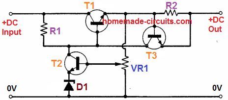
Thanks brother can you guide me to add autocut too in this circuit i searched alot but not found any circuit for autocut for 42v fully charged batteries and how much time batteries will take after adding this circuit I’ll set current limit to 700ma for 7ah batteries and 42v for 36v batteries..
You are welcome Happie,
You can apply the concept discussed in the following article for your 42 V battery. It will take at least 12 hours for the battery to get fully charged.
https://www.homemade-circuits.com/make-this-48v-automatic-battery-charger/
Any other solution ? 12hrs is too much ????
i seen your privious circuit having 3 transistors T1 is 142 T2 is 2n2222 i don’t know T3 value or I don’t need t3 in my circuit ?
Will this circuit helps to charge my batteries in less time..
12 hours is actually the standard time for any lead acid battery. This much time is required to ensure longer life for the battery. However there is a way to implement fast charging by initially applying high current and then reduce the current gradually as the battery gets charged.
You can try the following design for fast charging your battery.
https://www.homemade-circuits.com/fast-battery-charger-circuit/
The IC LM324 can handle only 32 V max, so you may have to connect a zener/resistor regulator to ensure that the IC does not burn at 42 V.
Sir your every circuit is really good easily understandable suggest me which one should i use autocut is not necessary as you said batteries took too much time to charge so I’ll remove charger manually when current goes 0 on amp meter so suggest me.. best one and i made one circuit if you take look into it or guide me it’ll be helpful me ???? will mine circuit work too ?
https://drive.google.com/file/d/1aWl7lz1n5Ua-GVHz1XzKuVm3Z9F3dYvI/view?usp=drivesdk
Thank you Happie, the circuit looks OK to me, however I have a few better and easier designs similar to your design. You can check out the circuits under the heading: [New Update] Current Dependent Battery Auto Cut OFF” from the following article:
https://www.homemade-circuits.com/high-current-10-to-20-amp-automatic/