
In this post I have explained how to build a simple yet powerful 32 watt amplifier circuit using a single chip TDA2050 and with a handful of resistors and capacitors.
By: Dhrubajyoti Biswas
Working Principle of TDA2050V
This article will detail building a stereo amplifier along with an output for a headphone jack. It is built by using the IC TDA2050V integrated circuit. According to the data sheet that comes along with the IC, TDA2050V is ideal for Class-AB based audio hi-fi amplifier.
The required operating supply voltage for TDA2050V should be in the range of +/-4.5V to +/-25V.
Using 25 watts of power you can achieve at least 65% efficiency. However, it is important to note that to maintain stability on the system the circuit gain should be managed with a gain of around 24dB.
We built the amplifier with an intent to use it with RB-51 bookshelf speakers. They are 8 ohms possessing a sensitivity of 92dB @ 2.83V / 1m.
Since this amplifier utilizes less power, therefore using TDA2050V is quite a right choice.
Moreover, the amplifier will also work with other audio devices, such as, tuner, mp3 player etc. It may be interesting to note that, the smaller TDA2050V chip produces a better quality sound than the bigger version.
Constructing the Amplifier
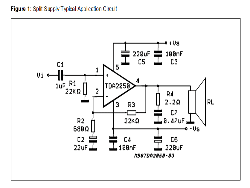
The above diagram is of an application that uses split-supply. The diagram is taken from the datasheet for ease of understanding. Also it is advisable to read the datasheet that comes along with TDA2050V chip. This will help to understand setting up the stereo in different ways.
The datasheet specified for the IC also details a recommended PCB design, which we have used as a reference for this experiment. The figure above, taken from the datasheet shows the basic PCB layout:
The amplifier that we have built in this experiment, its schematic design is presented below
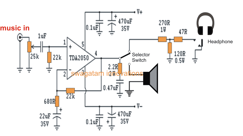
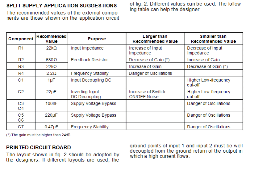
Schematic of hi-fi amplifier using TDA2050
To build the circuit, here we have followed the PCB design as shown in the above figure. Also, the circuit could be simply assembled on a perfboard.
In order to block DC current flow, we used a capacitor of 1uF MKT type. However, there is no such restriction and you are free to go for any other relevant capacitor as per your choice.
Constructing a circuit is not at complex. However, there are certain vital factors that should be kept in mind during design, as stated below:
- Grounding or earthing is very important to maintain low noise and an hum-free response from the system. This is why star grounding process is probably the best suited in this case. The system employs two ground points, use one for signal and the other for power, further connecting both of them via singular connection.
- For each channel use individual power supply.
- Keep signal wiring short and ensure the wires are twisted tightly. Maintain a distance with the AC power sources. Also it would be better if you can keep the wiring close to the chassis.
Power Supply
In this amplifier design the power supply adheres to the standard power supply regulations and employs snubbers for better safety.
Besides, we used torroidal transformer of 120VA and 18 Volt dual secondaries. Also we used 35A rectifier bridges, however, you can also use 15A – 25A bridge.
As per the design of specs, it uses MUR860 ultra-fast recovery diodes. You can also try other discreet diodes that are ultra-fast, but as per this experiment we figured out that it can be ignored and normal rectifier diodes can be used.
You can find 10,000uF capacitor for each power supply. The hum suppressed by the supply is quite inaudible albeit we could hear some on a microphone, when it has max volume and has no signal connection.
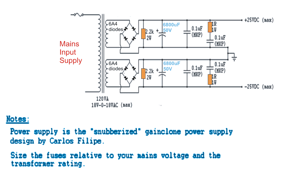
TDA2050 Power Supply Design
Cabinet
For the enclosure, here we used Hammond’s chassis [Model ID: 1441-24]– 12” x 8” x 3”, steel built and satin black in color.
The circuit board and transformer was carefully placed above just on the top of the enclosure. The volume control, headphone input and power button was placed at the front for ease of use.
We used gold-plated RCA standard jackets for the input. For output we used standard output plugs of three-way binding posts, which accepts bare wire, 4mm banana plugs or spade connector. However, please note that the binding posts of the speaker and the input jackets have their insulation from the chassis made by nylon spacers.
Heat Sink
As a standard procedure we have placed the heat-sink on the rear of the chassis, which is measured 50mm x 88mm with 35mm fins @ 2.9 C/W. Also we need to make a hole on the chassis so as to mount TDA2050 directly. As a note, please ensure TDA2050 is kept separate from the chassis because of the potential issue on TO-220 package. If this is not taken care of, then there is high chance of the chip to get destroyed once the system receives power.
In regard to isolation, you can use mica or silicon pads. Also please keep in mind to add a spacer for mountain crew to save the chip. Upon setting up the system, do finally check all the components and their placements. For instance, ensure a check to avoid continuity between heat-sink / ground / chassis and the chip.
As a conclusion, do maintain good thermal contact. Here we used thermal grease before mounting the system.
Another TDA2050 Amplifier Circuit with PCB Designs
The circuit diagram as shown below corresponds to an application note from the manufacturer. The TDA2050 is a power operational amplifier capable of delivering up to 32 W at 8 Ω and 35 W at 4 Ω.
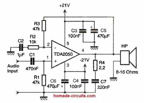
For our application, it is wired as a non-inverting amplifier with a gain of Av = 1 + R3/R2 = 5.7.
If we want to increase the gain, it is necessary to decrease the value of R2 while keeping the product of R2 and C2 constant. In fact, R2 and C2 define a low-frequency cutoff.
With the chosen values, we obtain F1 = 1/(2πR2C2) = 15.9 Hz. The low frequencies are also limited by the combination of R1 and C1 with a frequency F2 = 1/(2πR1C1) = 15.9 Hz.
Since F1 = F2, we have an overall second-order high-pass filter. The components R4 and C7 prevent the amplifier from entering an oscillatory regime. As for capacitors C3 to C6, they perform power supply filtering.
Power Supply
We opted for a regulated power supply at ±21V, which allows us to obtain the 30W from the operational amplifier.
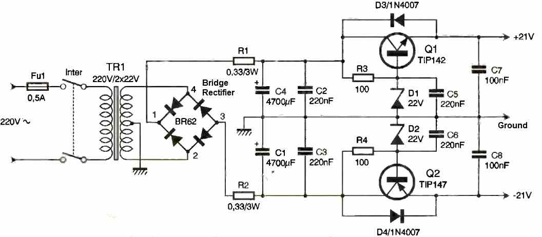
Its operation is fairly simple: a transformer provides two alternating voltages of 20V, which are rectified by a diode bridge.
Resistors R1 and R2 limit the current (I) during the initial charging of the capacitors (during power-up). This results in two DC voltages of ±26V, which we will then lower to ±21V.
To do this, we bias two transistors (Q1 and Q2) at fixed voltages, the values of which depend on the zener diodes D1 and D2 (22V). As for diodes D3 and D4, they protect the transistors from reverse voltage (when powered off).
Construction
The printed circuit board is relatively easy to make, whether using a direct etching method or a photographic method.
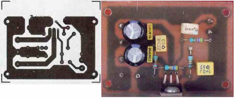
After verifying the continuity of the tracks with an ohmmeter and ensuring there are no short circuits, the components can be soldered in increasing order of size.
For both the amplifier and the power supply (Figures 4 and 6), radiators should be chosen with a thermal resistance lower than 2°C/W.
The comb-like profile is ideal, but other suitable formats can also be used depending on the board that will receive our assembly.
The power supply transistors must be isolated from the heat sink, but the amplifier circuit may not need isolation.
However, be cautious as the heat sink will be at a potential of -21V, and if you use a metal enclosure, beware of potential short circuits!
Finally, remember to attach the heat sinks to the printed circuits, as the heat generated by the amplifier and transistors can cause damage in a short period of time.
Testing
Before powering on the amplifier, it is important to verify that the diodes and capacitors are correctly installed.
No adjustments are necessary, and the amplifier is ready to operate. With 8Ω speakers, we obtain a sound of very good quality.
The power is sufficient for listening in a room of approximately 75m3, but it may not be suitable for sound reinforcement in a noisy party.
We have measured the following technical specifications:
- Output Power: 29W / 8Ω
- Frequency Range: 19Hz to over 40kHz
- Distortion: 0.5% at 25W across the entire frequency range
- Input Sensitivity: 2.7Vrms for maximum power (Pmax)
- Input Impedance: 47kΩ


With over 50,000 comments answered so far, this is the only electronics website dedicated to solving all your circuit-related problems. If you’re stuck on a circuit, please leave your question in the comment box, and I will try to solve it ASAP!