In this post I have explained how to build a homemade LED driver with dimmer and charger circuit for illuminating a 3D moon from a 5V USB source.
The idea was requested by Mr. John Sweden.

Circuit Objectives and Requirements
- I've been a visitor to your website for many years and wonder if I may ask your advice please.
- My friend in the US has an almost 2-year-old grandson who loves the moon! I hope it shines in his life as it has in mine. I'm a little older than he is (75) and have recently started to explore 3D printing on an Ultimaker 2+ printer.
- I would like to print him a 3D moon-sphere bedside lamp, maybe 12 to 15cm in diameter. It will be hollow and will use a model created by NASA with a hi-res representation of the moon with its craters and surface features.
- The white PLA (polylactic acid) filament I'll use is translucent and will allow a small LED to light it from the inside.
- The light I was hoping to use is a small-footprint, rechargable battery-powered PCB module made in Malaysia but no longer manufactured. The module slides in through a hole in the bottom of the moon and the whole thing sits on a base.
- The Malaysian module is described as:
Micromake 3D Moon light touch circuit board 200 mAh yellow dual color touch infinite dimming. - An example from AliExpress descibes it as: 240mAh Lipo rechargable battery, 0.5 watts, USB DC 5v, charging time 6 - 8hrs, stepless adjust touch switch and on/off.
- Do you know of a DIY circuit or module in your library that might be suitable for this project?
- I very much appreciate your help Swagatam!
Designing the DC LED Driver
As per the request, for illuminating the 3D moon with a natural feel, we would require a bi-color power LED, 5V LED driver circuit, a current controlled Li-Ion Charger, a touch operated switch and a Li-ion Cell.
I have selected higher specs for all the parameters for the present design, however for lower specs, the materials can be scaled down appropriately as per user preference.
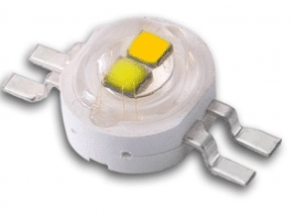
LED Specs:
- Bi-Color, Warm White, Cool Blue.
- 3.3V
- 0.9 amp current
- 3 watt, SMD
Battery Specs:
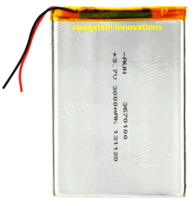
The battery can be a standard Li-ion or Lipo Cell rated at 3.7V, 3000mAh.
The Circuit schematic:
Circuit Operation
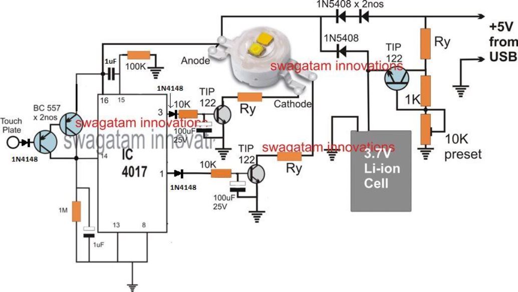
Referring to the above shown touch operated 3 D moon LED driver with charger dimer circuit, the supply input is obtained from a 5V source such as a USB, which can be assumed to be a constant voltage input.
The TIP122 along with Ry and the associated resistor, preset forms a simple current controlled charger circuit for the attached Li-Ion. The preset is adjusted to fix an approximately 4V across the Li-ion cell terminals.
Ry is appropriately calculated to make sure that the current to the battery never exceeds the 0.5C rate, which may be around 1.5 amps for the proposed 3000mAH battery. This TIP122 must be mounted over a suitable heatsink.
Ry may be calculated a follows:
R = V/I = (5 - 4) / 1.5 = 1/1.5 = 0.66 ohms,
wattage = 1 x 1.5 = 1.5 watts, or 2 watts
The DC to DC UPS Stage:
In the adjoining stage, we can see a few 1N5408 diodes positioned for creating a DC to DC UPS feature, which ensures that the LED inside the 3D moon continues to remain illuminated without an interruption even while the 5V USB source is removed or during a power failure, with the help of an automatic back up from the Li-ion cell.
The Touch Operated LED Dimmer Stage:
The next stage which is built around the IC 4017 forms a simple LED dimmer circuit. The pinout functioning of the IC 4017 can be learned with the following points:
Pin#3 which is the start pin of the IC and is supposed to be activated during power switch ON, is connected with one of the LED cathode pins through a TIP122 driver stage and a current limiter resistor Ry.
Let's assume this LED pin to be associated with the warm yellow color section of the LED, and will be responsible for generating a warm yellowish effect on the 3D moon illumination.
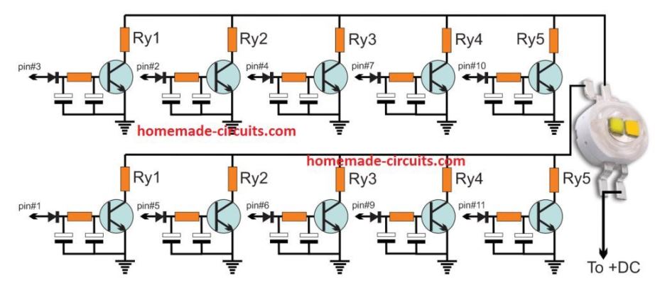
The next subsequent pins of the IC 4017, namely pin#2,4,7,10 are all supposed to incorporate identical TIP122 stages with varying Ry values connected and associated with the warm yellow pin of the LED.
The pinout details are not shown in the diagram due to lack of space, and since it is identical to the TIP122 stage attached with pin#3 of the IC and just needs to be replicated. The only difference being the value of the Ry which needs to be incremented suitably through calculation.
This implies that when these pins are sequentially toggled will enable a sequential dimming on the 3D moon LED brightness for the warm yellow section off the LED.
In exactly similar fashion pin#1 which initiates next to pin#10 can be seen associated with the other cathode pin of the LED through an identical TIP122 driver stage and a Ry current limiting resistor. The "cool blue LED" is supposed to get illuminated at this pin when the sequential toggling activates this pinout of the IC.
The following subsequent pinouts of the IC are supposed to have identical TIP122 stages for the cool blue LED side, as done in our above explanation with incrementing Ry values, connected with the cool blue pin of the LED.
When sequentially toggled pin#1 will illuminate the 3D moon with a cool blue bright light effect, and the next subsequent pins can be sequentially toggled for dimming this cool blue illumination to the desired lower levels.
As soon as the sequence reaches the last pinout of the IC 4017, which is pin#10, the sequence is designed to flip back to pin#3 and illuminate the warm yellow LED. In this way the 3D moon can be illuminated in two color with a sequential dimming effect.
The LED dimmer Switch.
The two BC557 attached to pin#14 of the IC 4017 are used for creating logic signals for the IC 4017 through finger touches, at the base of the BJT pair. Each touch results in a single sequential shift across the pinouts of the IC from pin#3 to pin#10 and back to pin#3 for the repetition.
Calculating the Dimming Resistor Ry
The Ry current limiter resistor and the dimmer resistor for the yellow and the blue sections of the LEDs may be calculated with the help of the following formula:
Ry = 4 - 3.3 / LED current
Here 4 is the input supply to the LED, 3.3 is the LED standard operating voltage, and the LED current is the amps which is responsible for implementing the dimming effect on the relevant sections of the bi-color LED. Therefore this current value needs to be calculated appropriately for enabling a sequentially decreasing current across the driver stages associated with the relevant pinouts of the IC 4017. Lower current selection will result in higher values resistors generating higher dimming effect on the 3 D moon illumination.
This concludes the making of the proposed 3D moon LED driver circuit with sequential dimming effect, if you have any doubts you may feel free to express them through comments...
Transistor Stage Configuration
The following diagram shows how the TIP122 stage needs to be repeated for all the 10 outputs of the IC 4017:
