

In this post I have explained a 48V solar battery charger circuit with high, low cut-off feature. The thresholds are adjustable through individual presets. The idea was requested by Mr. Deepak.
Technical Specifications
Hi Swagatam,
Thank you for UPS relay circuit.
I am trying to build it very soon. I will update you the result once i am done with that.
Next, i am very keen to build a Solar charge controller circuit for following requirement.
1. Battery shall be of 48 V (lead acid or maintenance free) with capacity go up to 48V X 600 AH.
2. Load to battery may be up to 1500 W (30 Amp at 48V)
3. Solar PV cell in series/parallel configuration producing voltage up to 60V and 40 Amps
The controller circuit is expected to perform as follows.
1. Cut off solar supply to battery when its voltage reaches approx 56V and maintain appropriate hysteresis to avoid frequent switching of power MOSFET. So the solar supply to battery would resume again only when the battery voltage reaches approx 48 V.
2. Low voltage disconnect of load from batter supply when battery reaches around 45 V and maintain appropriate hysteresis to avoid frequent power ON/OFF of load.
I will be grateful if you could help me building this circuit.
Thanking you.
Best regards,
Deepak
Circuit Operation
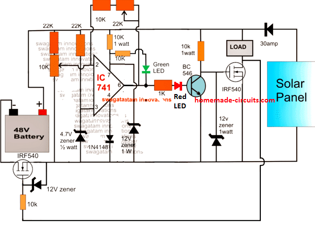
The proposed 48V solar battery charger circuit with high/low cut off feature can be witnessed in the following diagram.
The functioning of the circuit may be understood with the following points:
The IC 741 is configured as a comparator and is appropriately stabilized from the high 48V input using zener diodes and potential divider networks across its supply and input pins.
As requested, the input voltage which may be in excess of 50v is acquired from a solar panel and applied to the circuit.
The 10k preset is adjusted such that the power mosfet cuts off when the connected battery reaches the full charge level.
The 22k preset is the hysteresis control for the circuit and also serves as the lower threshold adjustment preset.
It should adjusted such the the MOSFET just initiates and switches ON at the preferred low battery voltage threshold.
Once the discussed set up is implemented and power switched ON, the discharge level of the battery drags the supply to around 48V forcing pin2 of the IC to go below pin3 potential.
This prompts the IC output pin6 to go high initiating the MOSFET connected in series with the ground rail so that the battery becomes integrated with the solar panel supply.
The above also switches ON the BJT BC546 which in turn makes sure that the associated MOSFET and the load remains switched OFF.
As soon as the battery attains the full charge level, pin2 is pulled higher than pin3 rendering the output to a logic low.
This instantly switches OFF the ground rail MOSFET and the BJT enforcing two things: cutting off supply to the battery and switching ON the load MOSFET such that the load now gets access to the supply voltages from the panel as well as the battery.
The feedback hysteresis network formed by the 22k preset and the series 10k resistors ensures that the above action locks ON until the battery voltage reaches below the predetermined lower threshold.
Circuit Diagram

Diagram
Feedback from Mr. Deepak
Hi Swagatam,
Thanks for Solar charge controller circuit.
The circuit appears to be little different than what i had requested. Let me reiterate the requirement again.
1. Solar panel should continue charging battery not beyond 56 V.
2. In the event of battery discharge, the charging process should resume again only when it reaches 48V. In other words hysteresis should be maintained.
3. Battery should continue supplying power to load when battery voltage remains in between 42 - 56V.
When battery voltage reaches 42V (due to battery discharge) the load should be disconnected from battery supply.
Once the load is disconnected, it should remain disconnected till the battery voltage reaches minimum 48 V during charging process.
Please confirm if the circuit works as above.
Implementing Window Comparator
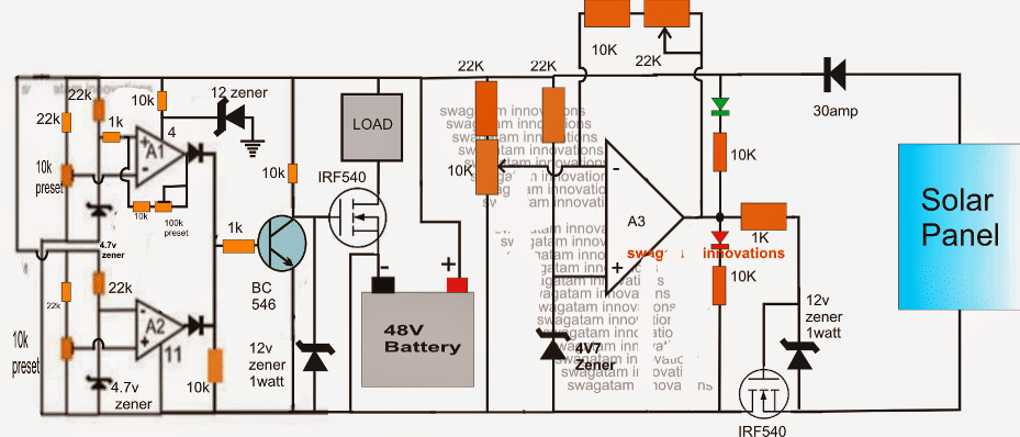
The above 48V solar battery charger circuit with high, low cut-off may be modified with these specifications by introducing a window comparator stage, as shown at the extreme left of the circuit below.
Here the opamps are replaced by three op amps from the IC LM324.
The window comparator is made by two of the 4 opamps inside the LM324.
A1 preset is set such that its output becomes high at the lower threshold level of 42V.
The 100k preset is for adjusting the hysteresis level so that the situation gets latched until 48V is reached.
Similarly A2 preset is set to make the relevant output go high at the higher threshold of 56V.
At voltages between these "windows", the BC546 remains shut off allowing the associated mosfet to conduct and feed the load with the required supply from the battery.
Once the thresholds are crossed, the BC546 is forced to conduct by the relevant opamp shutting down the mosfet and the load.
The A3 stage could also be replaced with an identical window comparator as discussed above for controlling the charging of the battery by setting up the presets appropriately, this would allow using all the four opamps from the IC LM324 and also make the operations much accurate and sophisticated.

Adding a Buzzer Indicator Stage
Another version of a 48V automatic battery charger cricuit using a buzzer indicator can be studied below:
The idea was requested by Nadia, please refer to the discussion between Nadia and me in the comment section for more info regarding the design
The transistor are incorrectly shown as BC547, which must be replaced with BC546 for preventing circuit malfunction and damage
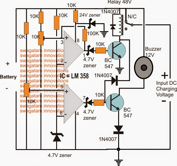
How to Set up the above 48V Battery charger circuit with buzzer
Do not connect the charging voltage from the right side.
Keep the 10k preset slider arm towards ground initially.
Connect a DC input using a DC variable power supply from the Battery side on the LEFT of the circuit.
Adjust this voltage to the required potential at which the buzzer needs to get activated....as per the request it should be at around 46V
Now adjust the lower 10k preset very slowly and carefully until the buzzer just activates and starts buzzing.
Seal this preset with glue.
Now increase the input voltage to the desired high cut off level.... which is 48V as per the request here.
Next, adjust the upper 10k preset very slowly and carefully until the relay just clicks. When this happens the buzzer should shut off.
The 48V solar battery charger circuit with high, low cut-off is now set, however the value of the 100k resistor which can be seen connected between the input/output pins of the upper opamp actually decides at what lower threshold the relay must deactivate again, and switch ON the buzzer.
It's been arbitrarily fixed, you may have to adjust the 100k value so that the relay toggles only at around 46V...it may be confirmed with some trial and error
48V automatic solar battery charger using relay

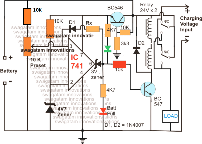
The operations involved with the first diagram above gets much simplified if a relay stage used instead of BJTs, and mosfets.
As can be seen in the above updated diagram, the relay stage is in the form of two 24V relays in series, wherein the coils are joined in series while the contacts are joined in parallel.
The sensing circuit is applied with a proportionately scaled down voltage through an emitter follower voltage divider circuit using the indicated BC546 stage for the intended battery level detection and cut-offs
The following diagram shows an extremely simple 48 V solar charger system which allows the load to access the solar panel power during day time when there's optimal sunshine, and features an automatic switch over to battery mode during night when the solar voltage is unavailable:
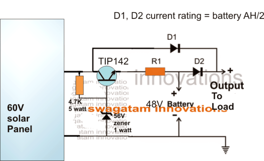
The emitter follower TIP142 ensures that the battery is never allowed to get overcharged above 55V.