The UPS detailed in this article can provide a power output of 50 watts consistently, at 110 volts with a frequency of 60 Hz. The output is fundamentally a sine wave that behaves exactly like standard mains home AC power for the load.
An integrated power supply works like a battery charger. Even though the UPS could be implemented for numerous different applications, it is mainly designed to power a small computer system and important peripheral, like a disk drive, to ensure that a power outages never causes deletion of data or interruption of the program that may be running at the instant.
This implies that this lead acid powered 50 watt UPS circuit is not going to handle bigger PCs, that usually work with over 60 watts of actual power.
One important feature of this UPS circuit is that it outputs a "clean" sinewave AC power: and flaws like noise, spikes, or low voltage within the grid AC line will never have an affect on the computer's (loads's) functioning.
Power Supply Relay Changeover Stage
The power supply stage is quite distinctive because it takes in power through a remote 12 volt lead acid or SMF battery and also from your AC power line, the battery here becomes the most crucial element for the UPS functioning.
As revealed in Fig. 1 below, when CHARGE-OFF-OPERATE switch S1 is positioned to either the CHARGE or OPERATE setting, relay RY2 is activated and its contacts provide AC power to the primary windings of the power transformers T1 and T2.
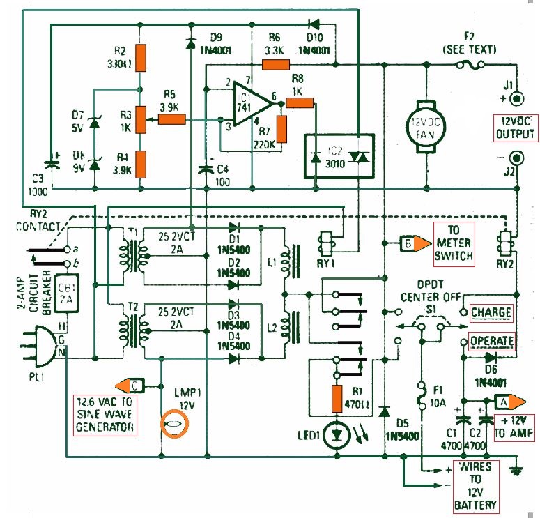
The current through the secondary windings is rectified through diodes D1, D2, D3, and D4.
Chokes L1 and L2 restrict the charging current for the battery as well as prohibit the passage of the ripple current.
Diode D5 delivers "crowbar" overload protection; its function is to safeguard the many vulnerable components by triggering fuse F1 to burn out in case the battery is accidentally hooked up with an incorrect polarity.
Op amp IC1 is connected in the form of an inverting voltage comparator whose reference voltage could be adjusted across a range of 11 to 14 volts through potentiometer R3.
Once the battery voltage falls beneath the reference, opto coupler IC2 is activated, that powers relay RY1. Current passing through RY1's contacts begins charging the battery when the load is not too heavy.
On other hand if the UPS is working at or close to its 100 % potential, an external battery charger may be needed to provide adequate current supply, to prevent the battery from getting discharged.
A 10 ampere battery charger is advisable. Given that the majority of battery chargers don’t have a filtration system, a high value filter capacitor must be included between the charger output and the battery to minimize ripple current.
In order to prevent battery overcharging, the supply from the charger must be switched on only when the UPS is being loaded at its 100 % capacity.
Fuse F2 must be less than 10 amps in order that the primary fuse, F1, may not whack when the 12 volt output is unintentionally shorted.
The Transistor Amplifier Stage
As presented in Fig. 2 below, the UPS AC output is generated from a transformer-coupled Class B amplifier circuit.
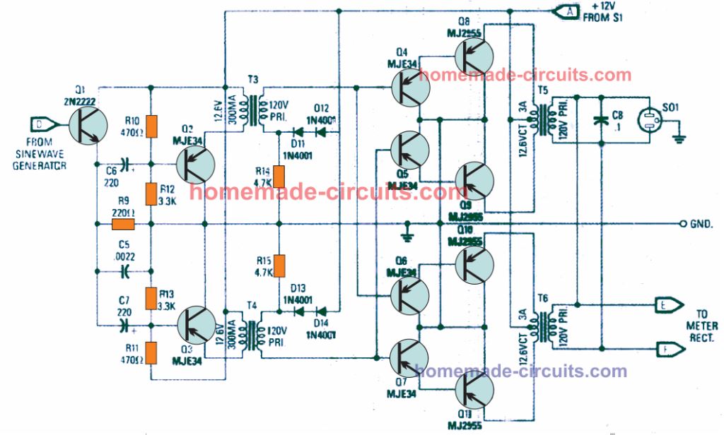
The 4 sets of Darlington transistors (Q4-Q8, Q5-Q9, Q6-Q10 and Q7-Q11) work llike emitter-follower networks to deliver voltage to the power transformers T5 and T6 primary windings.
Capacitor C8 cancels out any high frequency ingredients which originate due to high voltage crossover distortion or clipping, and in addition inhibits high frequency self oscillation.
Two of the Darlington sets are powered in parallel through transformer T3; another couple are pushed in parallel by means of T4.
Diodes D11, D12, D13, and D14 produce a constant DC base voltage which biases the output transistors at around the cutoff region.
The Class A driver network formed by the transistors Q2 and Q3, are similarly fully made up of emitter followers. The essential voltage step-up is implemented by the transformers T5 and T6, which are also typical power transformers configured in the reverse order.
Transistor Q1 drives transistors Q2 and Q3 in parallel. The Q1 base is directly connected to the IC5-d output (see Fig. 3), which is at 4.5 volts DC.
Reversal of Phase for push-pull drive of the output stage is achieved by appropriately wiring the secondaries of transformer T3 and T4 transformers.
The Sinewave Generator
As revealed in Fig. 3 below, the oscillator stage is configured using IC4, which is a 567 tone detector.
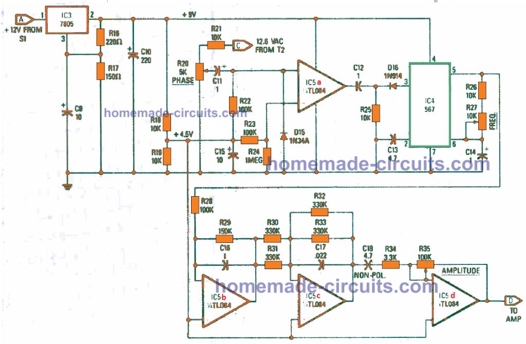
The IC's frequency is set up by resistors R26 and R27, and capacitor C14, and is fixed to a precise 60 Hz. IC4's square wave output is transformed to a triangle wave by IC5-b, which is further on converted to a sinewave by IC5-c.
Op amp IC5-d's gain is set by potentiometer R35, that is fixed at the AC output voltage.
Op amp IC5-a converts the sinewave from the T2 output to a 60 Hz frequency.
D15 safeguards against damage that may take place in case the op amp inverting input happens to turn negative with reference to ground; the diode is generally reverse biased.
The 60 Hz pulses, that are connected to IC4 via C12 and D16, trigger the oscillator to lock to the grid AC frequency. Some extent of control on the precise phase synchronization is achievable by fine-tuning potentiometer R20.
Once correctly tweaked, the AC output is going to lock in-phase with the input AC grid line, and this locking/unlocking process during the input power failure and restoration would be soft and favorable, producing almost no interference.
The sine wave generator comes with smooth, ripple-free 9 volt power through IC3, a 7805 IC, 5 V regulator. Pin 3 of the regulator is kept at 4 volts above ground line with the help of resistive divider R16 and R17 to get a precise 9 volts output.
The Meter Circuit
It may be possible to monitor either the battery voltage or the AC output voltage through a meter circuit as exhibited in Fig. 4 below.
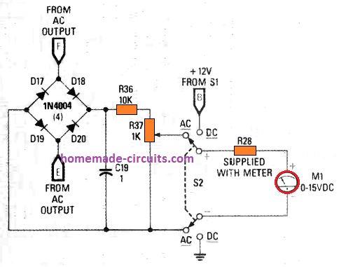
A bridge rectifier consisting of four rectifier diodes converts the AC to DC, while the capacitor C19 smooths to a pure DC.
A DPDT switch hooks up a 15 V DC voltmeter with the 12 V supply or the voltage divider built using resistive divider of R36 and R37.
How to Test the Power Supply Changeover
It may be important to test the power supply section before the amplifier is wired up. This can be carried out before even the amplifier stage is assembled.
For this you can adjust the R3's slider arm towards the end which is linked to R4.
Do not connect the mains-cord into an electrical outlet yet. Attach a 12 V lead acid battery to the supply and position S1 to either CHARGE or OPERATE.
Now, the relay RY2 could be seen activated and LED1 illuminated. At this point you may find around 12 V at pins 2 and 7 of IC1.
Pin 6 should show logic low. Next, connect the mains cord into an AC outlet. Lamp LMP1 will now light up. Relay RY1 should continue to be switched OFF and you would test approximately 14 V at its normally open contacts.
Pin 7 of IC1 should indicate around 14 V and pin 3 around 11 volts. Pin 6 should indicate a logic low.
Turn R3 to its reverse end to get 14 V at pin 3; RY1 at this moment must activate with LED1 shutting OFF.
The voltage across the battery points should now read 13 V. Adjust R3 just around the level at which relay RY1 deactivates.
The charger stage must keep switching off and on as the battery voltage goes up and reduces. The accurate setting of R3 may be at the point, where the charger output switches quite rapidly, and switches off practically the moment it switches on.
The battery voltage should be around at 12.5 V mark in the absence of a charging supply. When the battery voltage drops, the charger output must begin switching repeatedly unless of course the battery is so terribly discharged that the full current of the charger is not able to restore the voltage back up to 12.5.
Testing the Sine wave Generator
The testing of the sine wave generator stage can be executed separately. In case you assemble it on the shown PCB without the 9 V regulator IC, then you can use a 9 V PP3 battery or an external equivalent power source for the testing procedure.
Begin by positioning preset R20's slider arm to its ground side. Using an oscilloscope scope should display a square wave signal at pin 5 of IC4.
By supplying a 60 Hz sinewave frequency to the scope's horizontal sweep, adjust resistor R27 to get a frequency of 60 Hz that will generate a rectangular Lissajous waveform.
The frequency does not have to be precisely accurate. A gradually altering waveform pattern can be quite satisfactory. Having the scope set for a standard 60 Hz sweep, make sure the scope indicates a triangle wave on the output of IC5-b and a sinewave at the output of IC5-c.
A sine wave must also be available at the IC5-d output. And its amplitude should vary in response to the adjustment of R35. In case any of these checks tend to be incorrect, examine the presence of a 4.5 volts DC across all the input and output pins.
Next, connect a 12.6 V AC source to R21, and adjust the R20 until the you find the scope showing the output pulses from IC5-a: The oscillator freqeuncy must lock to the input line frequency. Now set the scope to display a Lissajous curve as done previously and monitor the IC5-d output.
You must see an oval pattern which is almost closed. You must be able to possibly fine-tune R20 such that the scope display is almost a sloping straight line, showing that the output signal is in-phase with the grid-line.
Now, if you disconnect the input AC signal by unplugging the mains-cord, the scope pattern must start producing a gradual change to an oval shape display which opens and closes.
Re-allign the potentiometer R27 to reduce the above rate of change. As soon as the input AC frequency is reconnected back, the scope display must instantly come back to the sloping line pattern.
Testing the Meter Circuit
The testing and calibration of the meter circuit could be implemented by attaching the rectifier to the grid AC line.
Pushing S2 in the AC position, fine-tune R37 to get a meter reading that may be 1/10th of the AC input voltage as measured separately through an standard meter reading.
If you find no measurement appearing, look for around 130 volts DC around C19 to ensure that the rectifier is correctly joined. A scope here should display a big ripple element due to the low uF value of the C19 capacitor.
Testing the Amplifier
Begin the test by integrating the power transistor amplifier stage with the 12 V power source and the input sinewave waveform generator.
Adjust the R35 center arm towards end associated with the output side of IC5-d, which decides the setting for a zero output signal.
Now shift the S1 to the "OPERATE" position. You should see a meter reading of 12.5 V at the emitters of Q2, Q3, Q8, Q9, Q10, and Q11.
You may also find these transistors getting a bit warmer, although not hot.
You should be able to see a meter reading of around 11 V at the bases of Q4, Q5, Q6, and Q7, and around 4 V at the Q1 emitter.
While conducting the following testing procedures, be careful while working with the output, since this would be at a lethal mains 117 V level.
Hook up one wire of each of the 120 V windings of the transformer T5 and T6 with each other, leaving the others remain unconnected.
Connect an AC voltmeter with one of the transformer windings and set the meter to a range greater than 110 volts.
After this, little by little turn R35 preset center arm until you see a measurable output voltage. If you don't find this happening, ensure that phase drive into the output stages are reversed.
The AC voltage from the Q4 or Q6 base to the Q5 or Q7 base must be double the reading to ground. If you don't see this, try swapping the winding connections of either transformer T3 or T4, but not both.
Next, ensure that the 120 V windings of transformer T5 and T6 are perfectly in-phase and thus connected in the appropriate manner. Attach the voltmeter across the leads which were left unconnected.
If you find the voltage is two times more than the earlier reading, then the windings are surely connected in series. Quickly reverse the connection of one of the windings.
If you fail to see any voltage reading on the meter, connect the other two leads with each other. Link up a 15 W lamp at the output, and set up preset R35 to get a full output. The lamp must illuminate with optimum brightness and the meter should indicate around 125 volts AC.
How to Use the UPS
While implementing the proposed 50 watt UPS circuit, make sure to set S1 at "OPERATE" before switching ON the load.
Verify the AC output from the UPS to make certain that it is producing a minimum of 120 volts. This 120 V voltage might decrease a bit as soon as the output is loaded.
If you find the voltage is unstable, it would mean that the oscillator hasn't locked and synchronized with the mains grid power line. To correct this try readjusting the presets R27 and R20 after sometime, once the circuit has warmed up a bit.
When you tweak the R27/R20 presets appropriately, you will find the oscillator locking with the AC mains frequency during each switch ON periods.
Now, switch ON the system and reconfirm the output voltage conditions. The output voltage may drop to 110 volts while it is being operated in discontinuous load, say for example a disk drive or a printer, and this may be acceptable.
The back up time from the UPS during a mains outage would depend on the Ah rating of the battery. When a motorcycle battery is used, it should provide approximately 15 minutes of back up operational time.
Pars List
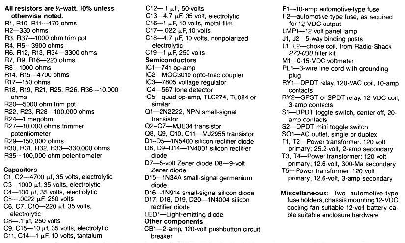
The complete parts ;list for the above explained 50 watt sinewave UPS circuit is presented in the following image:
How to Construct the L1, L2 filter chokes
If you are unable to obtain the suggested L1, L2 chokes from your part dealer, you can construct the same using the following configuration
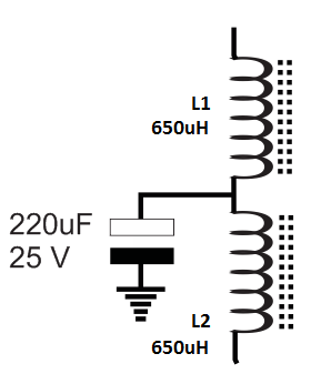
Use 1 mm super enameled wire for the coils