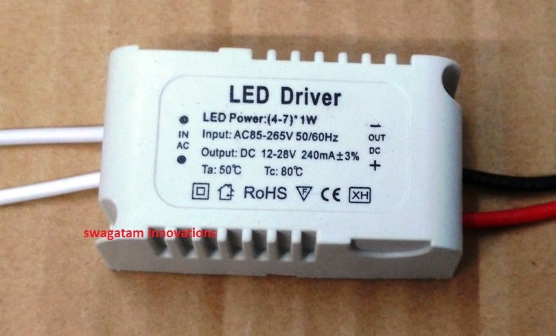
The presented 7 watt LED driver circuit is an SMPS based non-isolated, transformerless circuit which ensures a safe current controlled output for the attached LED, it is very affordable to build without involving complex transformer winding.
Constant Current and Load Regulation Objective
The aim behind the design of the IC TPS92310 (from TEXAS INSTRUMENTS) is to offer a constant current line and load regulation to the load through a primary side sensing flyback inductor, which operates in the critical conduction mode, and eliminates the need of the traditional opto coupler based secondary side feedback control.

The proposed design employs a non-isolated single inductor smps design and thus removes the obligatory transformers, making the design much compact and involving less BOM, yet meets the standard performance criteria of an LED driver specifications.
The design also includes a PFC stage for ensuring a cleaner output and satisfy the modern PFC IEC 61000-3-2 rules
The following explanation provides us with the operating principle of the proposed 7 watt LED driver SMPS circuit:
Circuit Diagram and Functioning
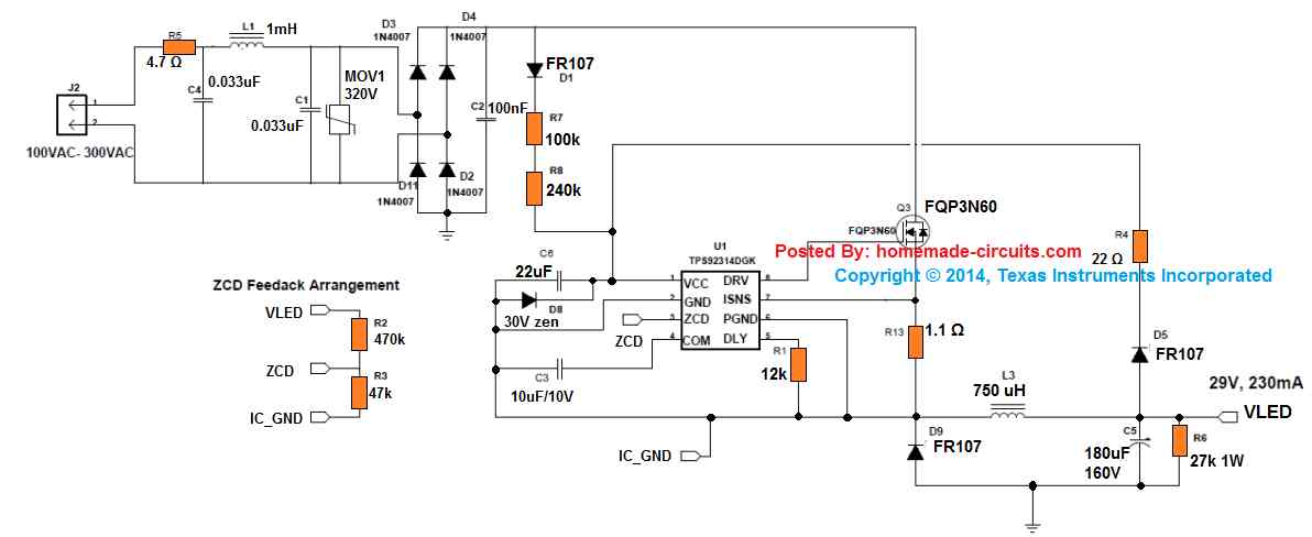
1) The LED controller chip TPS92314A includes an advanced constant ON-time control feature for ensuring a high power factor at the input, and quasi-resonant switching for guarantying greater efficiency and minimum EMI emission.
2) The design facilitates load power regulation through the stored energy of an inductor configured in the form of a high-side buck converter .
3) The inclusion of a diode/capacitor at the output additionally regulates the DC content, without depending on any extra auxiliary winding which is commonly seen in traditional isolated forms of SMPS designs...here this is eliminated causing the unit to become very compact, highly efficient and cost effective.
4) The figure shows a standard full bridge rectifier network at the input for converting the alternating input current into a single positive AC bus.
The pulsating sine voltage here faithfully follows the pulsating sine current. due to the presence of a 100nF capacitor immediately after the bridge rectifier, and this helps in maintaining a high power factor response.
5) The above processed supply is fed to the drain of a mosfet which is configured as a high side switching device, having its source hooked up with D8 freewheeling diode along with inductor L3 and output capacitor C5.
6) In the figure the IC input side of the IC could be seen referenced to a switching junction SW, which makes sure that the IC does not switch ON until the processed AC has a potential higher than the connected LED's forward voltage value, and also for so along as the input is not drawing any current. This parameter causes a delay factor during power switch, and can be calculated through the following expression:
Δ T = Sine (inverse)VLED / √2 xVac
During the critical conduction mode periods of the IC TPS92314, the peak current from the inductor becomes two times more than the input peak current.
The inductor value for this 7 watt LED driver SMPS circuit can be calculated using the following formula:
L = [1.41 x Vac - VLED] x Ton / ΔIpeak
Due to the fact that this IC involves a critical conduction mode operation implies that the every subsequent ON periods is initiated only once the current within the inductor has ramped down to almost zero.
A feedback voltage in the form of VLED is applied back to the IC which acts like a supply voltage for the IC, because VLED can be seen linked with the input side bridge network ground. This particular implementation allows the design to comfortably work with only a single non-isolated inductor and gets rid of the complex extra biasing winding.
This makes this 7 watt non isolated SMPS LED driver circuit extremely compact, durable, efficient and very long lasting and also compliant with the present SMPS laws.
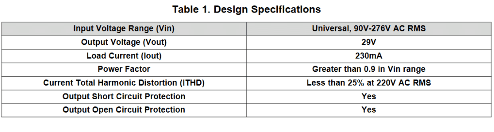
Design Specifications
The design can be adapted for all power LEDs ranging from 1 watt to 7 watt.
The main specifications of the driver circuit can be witnessed in the following table:
Complete Datasheet Here
Dear Mr Swagatam
thanks for the support, As discussed I would like to serve the city colonies with LED Lamps with 1year guarantee for free replacement immediately in case the bulb fails.
For this purpose, I may have to maintain a bank of different bulbs at my office. The cost of maintaining the bank and the cost of replacement has to be included in the selling price, against stiff competition. In view of the above, I would request you to kindly suggest me the landed price of each bulb mostly with B22 base. pl also suggest if I assemble the lamps myself whether it would provide me with a cushon in making a profit and maintaining commitment, Further you have not given the prices of electronic components for repair and services please add them and oblige. the
Dear PK Maitra, I can only provide information about the technical aspects of an electronic circuit, for learning and personal use, I cannot help with the business related aspects of the unit.
Hi there,
I’m was designing a prototype model of Low cost 5 Watt LED Driver, it is based on switched mode power supply which can be fixed in LED bulb housing.
I need assistance that what type of smps either buck or boost should I use while considering the cost and size.
Also should I use a transformer in it or not?
Looking forward for assistance !
Regards,
Asim
Hi, if the driver is intended for 220V or 120V operation then obviously the circuit will be a buck converter, isolated or non-isolated. Transformer will not be required if a non-isolated type SMPS is used
Gear Swagatam,
My name is Pravin, I have been using your wonderful circuits when I was working as Physics technician at Upton Court Grammar school. I have recently retired and like to do things that I never had time when I was working.
I would greatly appreciate if you can help me in making a simple circuit for LED driving red, green and blue. This will be lighting up my water fountain. I would like each colour in the rainbow. In other words, After red colour it gradually through yellow to green to cyan to blue to magenta and back to red and so on. Each colour taking minimum
10 seconds before moving on. If this can be adjustable that will be brilliant.
Your help would be greatly appreciated.
Regards,
Pravin
Thank you dear Pravin, I think you can give the following design a try, it should solve your requirement:
Thank you very much for your quick response. Yes I will try it and hope it will give the effect I am looking for. When I am done I will send you a photo of the finished water fountain.
Regards,
Pravin
No problem, let me know if you any problems!
hai sir,
please help me to make own metal(al/cubase) clad pcb. i could not found how to print the board.
i am waiting for your replay
thanking you
Mkumaran
Hi Kumaran, I am sorry I do not have any information about aluminum base PCB construction, you may have to consult a professional PCB designer for this.
good after noon sir how use in 18watt led light of bit type capectar value in pcb
nikhil, the above circuit cannot be used for driving 18 watt LED
Respected Sir,
Good Morning, this is Vijay from Bangalore nice to u meet Sir. I have an inquiry regarding 500 LUX LED Tube Light with 18W. Sir is that any possible to make it on this kind of lights.
Kindly please help me with this inquiry.
Hi Vijay, yes you can but an 18 watt will not work on a 7 watt driver, because the light will get affected.
can you specify the voltage rating of the LED, then I may suggest an alternative driver circuit accordingly
Dear sir,
can you please provide LED driver circuit use LIS8411 ic
Sir,
In your below circuit, the value of one resistance( series to LED line) not mentioned. pl help. https://www.homemade-circuits.com/2016/07/scr-shunt-for-protecting-capacitive-led.html
Thank you sir.
KR, you will have to calculate it with the following formula:
(zener V – Total LED FWD V) / LED Current
Thank you for kind information. Sir one more request Can you give me low cost circuit using voltage dropping capacitor ?
You are welcome KR, you can apply the following concept for your requirement
https://www.homemade-circuits.com/2016/07/scr-shunt-for-protecting-capacitive-led.html
you will have to put all the LEDs in series and use a zener value that may be slightly higher than the total LED FWD Voltage value, that is 7 x 3.3 = 23.1 V or a 24V zener
Sir,
Please post a 1w x 7nos white led circuit for panel light
KR, you can try the above explained design, you can put all the 7 LeDs in series without any resistors.
or you may also try the following design
https://www.homemade-circuits.com/2014/02/simple-1-watt-to-12-watt-smps-led.html
Sir can u please help me to make circuit, when i switch on my bullet with key i want to hear a beep tone 3 or 4 second then stop. Same as when i switch on our computer ups as we hear beep tone. Sir one thing i want to tell u that their on ignition their is a also a dc +12 volt. Sir please send me soon a circuit diagram as per my request.
Taslim, you can do it in this way….buy a ready made 12V piezo buzzer, connect it with the ignition +12V through a 10uF/25V series capacitor, and also connect a 220K resistor parallel with the capacitor.
this capacitor could be in series with the positive of the buzzer or the negative, but make sure the relevant terminal of the capacitor goes to the matching polarity of the supply.
sir,
take your time to create circuit….i just reminded you only
NVD, I have updated the design in the above linked article, you can check it out
sir
i earlier made a request to u.
can you provide a simple candle circuit with ldr and puff off feature.candle should lit when matchstick is brought near it.it should off when we blow..waiting for ur reply
NvD, I'll try to do it soon, actually the same circuit which is I have explained below can be transformed as per your requirement
https://www.homemade-circuits.com/2011/12/make-electronic-candle-at-home.html