In this post I have explained how to build a simple 70 + 70 watt stereo power amplifier circuit using transistors. The entire design along with power supply and PCB layouts are provided in the following article.
Circuit Description
The working of the proposed 70 watt stereo amplifier circuit can be understood from the following explanation:
Only one channel is shown in the following diagram, two such identical channels will be required for getting the left, right stereo effect.

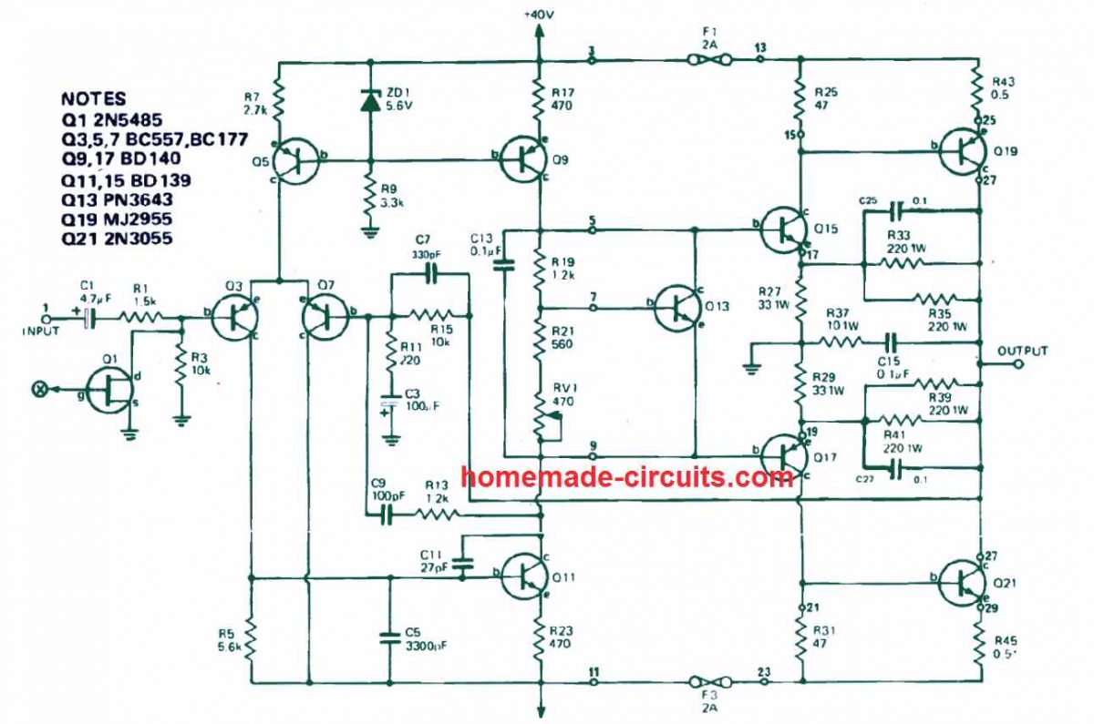
Referring to the circuit diagram above, the music input signal is applied through C1 and R1 to the Q3 base. Transistor Q3 along with transistor Q7, works like a a differential pair. Transistor Q5 is configured like a constant current source wherein the current is determined using the formula is 15.6 V (ZD1) - 0.6 (Q5)/2700 (R7), which is approximately equal to 2 mA. This current is uniformly used among the transistors Q3 and Q7.
Transistor Q9 also serves like a constant current source delivering around 10 mA which, under the absence of an input signal, in driven by means of Q13 and Q11. The differential transistor pair regulates Q11 which in turn controls the voltage at its collector.
The R19 and R21 resistor along with the potentiometer RV1, regulate the voltage across Q13 to approximately 1.9 volts.
However since Q13 is attached to the heatsink, this voltage might fluctuate as the heatsink temperature changes.
Supposing that the voltage on the indicated points 5 and 9 is spread uniformly to around zero volts (ie ± 0.95 volts), the current is going to be fixed at approximately 12 mA by means of transistors Q15 and Q17.
The 47 ohm resistors which are R25 and R31, create a voltage drop which becomes sufficient to slightly switch ON the output transistors so that it produces around 100 mA quiescent current. This quiescent current can be, adjusted and set through the potentiometer RV1.
The resistor R33, R35, R39, R41 are configured and used for applying the local feedback to the output stage. This provides the output stage with a voltage gain of about four.
The general feedback achieved through the resistor R15, helps the amplifier to get the necessary gain control. The fuses ensure that the amplifier remain protected from output short circuits and overload conditions.
To achieve good temperature stability Q13 must be attached to a suitably rated heatsink. Q13 can as a result automatically adapt and regulate bias voltage.
The parts C9/R13, CS, C7, C11, C25 and C27 are used to include sufficient frequency stability for the amplifier.
Prevent Thump Sound
Even though this 70 watt stereo power amplifier on its own is not going to cause a power switch ON "thump" sound through the loudspeakers, a preamplifier circuit if used might cause this issue.
In order to minimize any kind of thump sound on the speakers, Q1 is incorporated to enable short circuiting of the input stage for approximately 2 seconds on every power switch-on and instantly during the power switch-off.
Power Supply

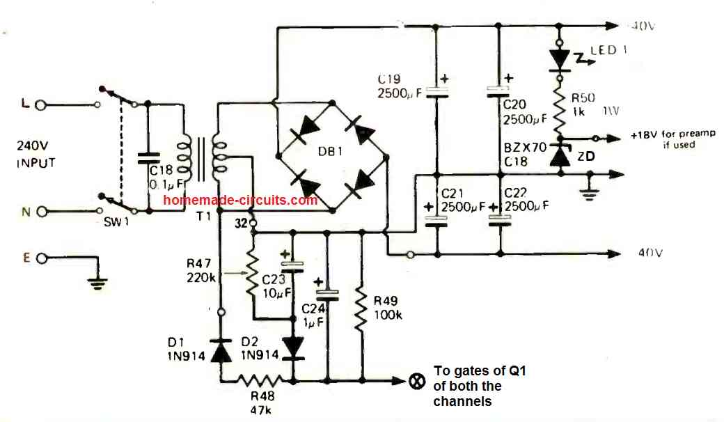
The power supply is actually a standard full-wave bridge having a center tap, which generates a dual supply of + 40 volts and -40 volts and ground voltage for operating the 70 watt stereo amplifier.
Diode D1 does the rectification of a second negative supply which is employed for controlling the Q1 FET for both the channels. Because of the inclusion of a series resistance with the diode, the capacitor C24 is charged slowly. Furthermore, while C23 is charged it also adds a slight delay to the power switch ON and switch off.
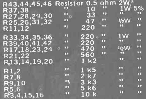
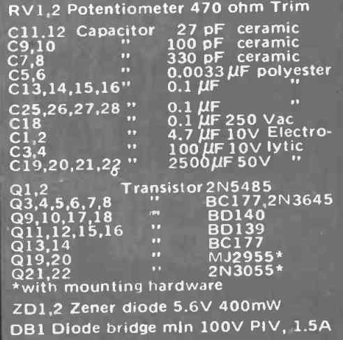
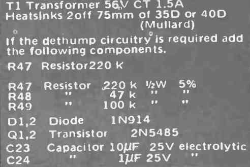
Parts List


How to Set Up
The only setting up procedure this 70 watt stereo amplifier circuit needs is for the bias current. This setting up can be ordinarily completed with an ammeter connected in series with the power-supply at the output stage. While doing this procedure make sure that the speaker is unconnected with the amplifier output and the input is short circuited to ground.
After this, preset RV1 is tweaked to secure a current of approximately 20 milliamps.
But remember, in case a significant error is present, or happens, implementing this procedure will cause the ammeter and also the output transistors to be destroyed.
In order to prevent this we propose an alternative setting up procedure which is as follows.
Remove the fuses and momentarily attach 220 ohm half-watt resistors right over the fuse holders. Now start adjusting RV1 until around, 4 volts is achieved across these 220 ohm resistors.
In the event that a serious fault is present the 220 ohm resistors will begin sizzling and may just burn up.
But any other kind of serious harm will never happen to the amplifier since the resistors would restrict the absolute maximum current to the amplifier circuit.
Once the above explained bias set up is completed you can remove the 220 ohm resistors and replace the fuse holders with actual fuses.
During the above set up process you may see that the voltage across the 220 ohm connected at the positive side fuse holder is a little bit different from that of the resistor attached in the negative lead. It is because a minor offset that may exist within the output voltages. However as long as the typical value of around 4 volts is achieved, that would be just enough.
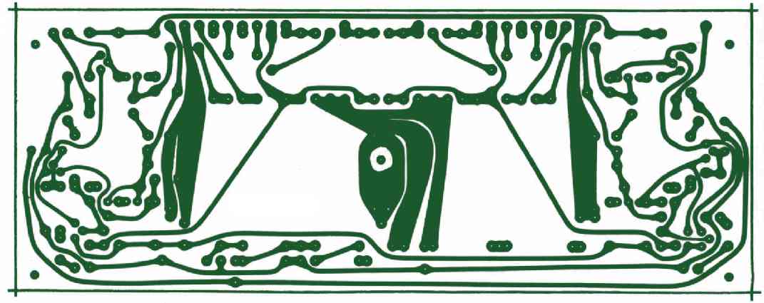
PCB Design