The following article discusses a few very simple intrusion detector circuits, or ant-theft alarms. The presented designs are easy to build yet extremely effective with the functions.
How the Circuits Works
An intruder alarm basically consists of a sensor and a trigger stages, which work together to produce the required detection.
The sensor detects the presence of an intruder while the triggering stage responds to the sensor detection by instantly raising the alarm.
The triggering stage may consist of a voltage/current amplifier stage rigged with a relay driver stage along with a timer stage for keeping the triggering switched ON even after the threat is eliminated, for increased safety.
The sensor pat is generally more sophisticated because it's the main section responsible for detecting the threat.
Generally infrared sensors which work by detecting body warmth are incorporated in most hi-end types of anti-theft alarms, however here we'll try to implement reasonably similar results yet use ordinary arrangements for the sensor stage in the proposed circuits.
You may also want to build this PIR burglar Alarm Circuit
Intruder Alarm Using an Ordinary Conductor as the Sensor
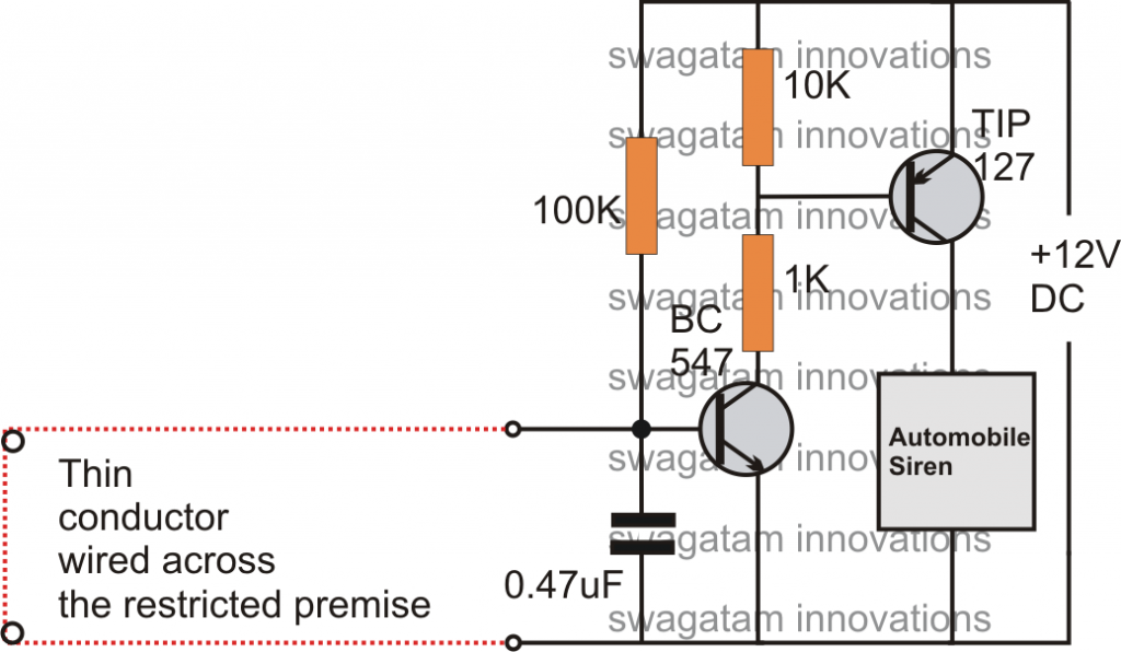
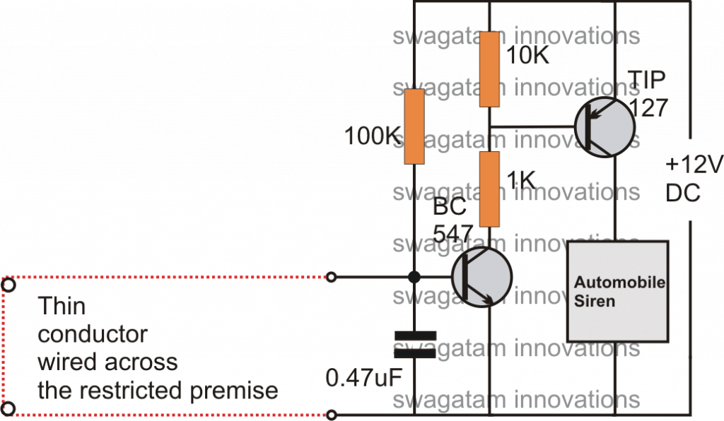
This is probably the simplest one among all. As shown in the circuit diagram, the sensor is an ordinary thin wire conductor which is laid across the restricted area in such a way that anybody intruding the place gets caught up against the conductor and in the course breaks it up.
Once the wire breaks, the transistor is allowed to receive the required base drive, ringing the attached alarm.
Intruder Alarm Using a Piezo Electric Sound Sensor
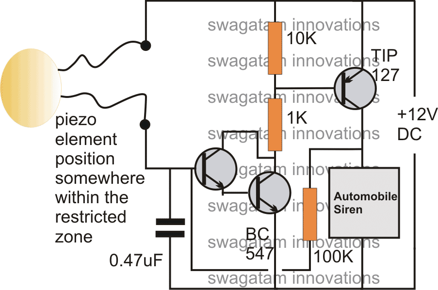
This circuit is based on a sound detection through an inexpensive piezo element.
The entire system may be fixed over the door or the restricted entrance. If an intruder tries to break in, the door would be disturbed instantly activating the connected piezo sensor, and the preceding alarm circuit.
Intruder Alarm Using a Laser Beam.
Today toy laser beam generator devices are pretty popular, and can be easily procured ready made from the market.
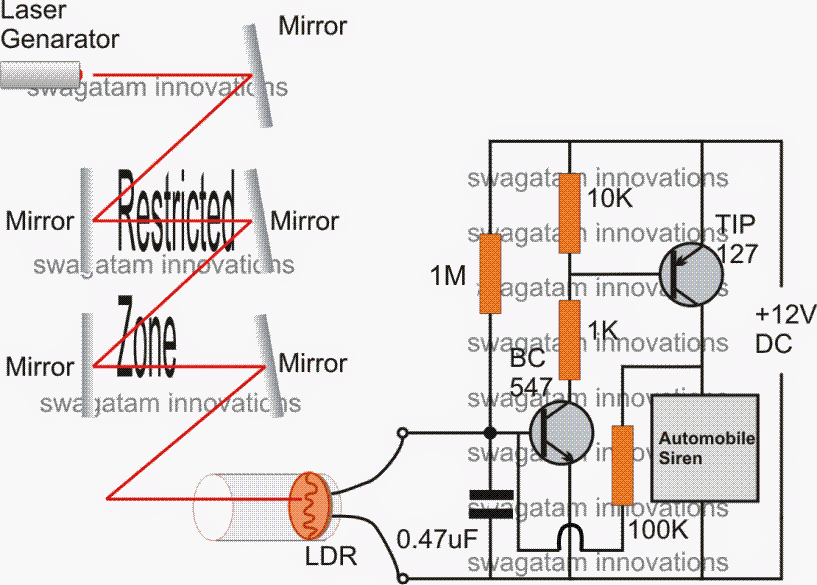
This toy laser beam can be effectively implemented as an alarm sensor. As shown in the figure, the restricted area may be swarmed by laser beams reflected across the area via accurately angled mirrors.
The final reflection gets directed toward an LDR trigger circuit. In case an intruder tries to trespass the premise, the person would block at least one of the reflections, interrupting the laser passage over the LDR.
This would result in an instant triggering of the connected driver circuits.
Intruder Alarm with Push Button OFF Feature
The above design of a latching laser activated alarm can be modified with a push button OFF feature.
The following diagram shows how it's implemented using a single SCR, while the LDR, and the laser set up remains the same.
The idea was requested by Mr. Kuldeep
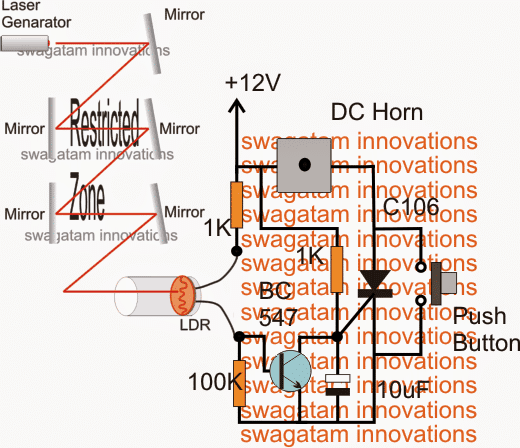
The 12V input power should be switched ON only after the laser point is set on the LDR.


With over 50,000 comments answered so far, this is the only electronics website dedicated to solving all your circuit-related problems. If you’re stuck on a circuit, please leave your question in the comment box, and I will try to solve it ASAP!