The electric fence charger circuit presented here is basically a high voltage pulse generator. The super high voltage is derived from a commonly used automobile ignition coil.
An astable multivibrator is used to generate the required frequency to drive the ignition coil. Another astable is used to control the pulses supplied to the fence.

Protecting Crops with Fence Charger
If you have large agricultural fields and desperately need to protect the crops from uninvited guests like animals and possibly humans, then this electric fence charger device is just what you are looking for. Build and install it yourself.
An electric fence is an electrified high voltage barrier which produces painful shocks if physically touched or manipulated.
Thus such fencing basically function as deterrents for animals as well as human intruders and stop them from crossing the restricted boundary.
The present circuit of an electric fence charger is designed and tested by me and has proved sufficiently powerful for the application.
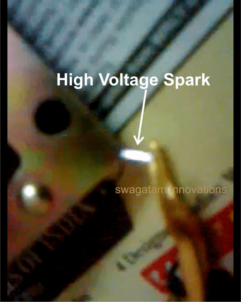
20 kV from the Sparks
The fence charger circuit is able to produce voltage pulses up to 20,000 volts, needless to say about the fatality rate involved with it.
However the pulses being intermittent, provides the subject with enough time to realize, recover and eject.
The generated pulse is so powerful that it can easily arc and fly-off between short distances of around a cm. so the fencing conductor needs to be separated adequately to avoid leakages through arcing and sparking. If not tackled, may drastically reduce the effectiveness of the unit.
Here the generation of high voltage is primarily carried out by an automobile ignition coil.
The winding ratios of an ignition coil are specifically designed and intended for creating high voltage arc between a two closely spaced conductors inside the ignition chamber to initiate the ignition process in vehicles.
Basically it’s just a step-up transformer, which is able to step-up an input applied voltage at its primary winding to monstrous levels at its output or the secondary winding.
WARNING: SOME POINTS OF THE CIRCUIT AND THE IGNITION COIL IS VERY DANGEROUS TO TOUCH WHEN POWERED. ESPECIALLY THE IGNITION COIL OUTPUT IS TOO LETHAL AND MAY EVEN CAUSE PARALYSIS. APPROPRIATE CAUTION IS STRICTLY RECOMMENDED. THE AUTHOR CANNOT BE HELD RESPONSIBLE FOR ANY MISHAP.
Let’s diagnose the proposed electric fence charger circuit more deeply.
Circuit Operation
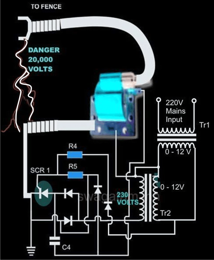
In the CIRCUIT DIAGRAM we see that the entire circuit is basically comprised of four stages.
A DC oscillator stage,
An intermediate 12 to 230 volts step-up stage,
The voltage collector and firing stage and the super high voltage-booster stage.
TR1 and TR2 are two normal step-down transformers whose secondary windings are connected through SCR2. TR1 input primary winding may be selected as per the country specification.
However, TR2 primary should be rated at 230 volts.
IC 555 along with the associated components forms a normal astable multivibrator stage. The supply voltage to the circuit is derived from the secondary of TR1 itself.
The output from the astable is used to trigger the triac BT136 and the whole system, at a particular fixed intermittent rate as per the settings of P1.
During the ON periods, the triac connects the 12 volt AC from TR1 to the secondary of TR2 so that a 230 volt potential instantly becomes available at the other end of TR2.
This voltage is fed to the voltage-firing stage consisting of the SCR1 as the main active component along with a few diodes, resistor and the capacitor C4.
The fired voltage from SCR1 is dumped into the primary winding of the ignition coil, where it is instantly pulled to a massive 20,000 volts at its secondary winding. This voltage may be suitably terminated into the fencing.
The high voltage generated by this electric fence charger will need to be carefully applied across the whole length of the fence.
The two poles from the ignition coil connected to the fence wiring should be kept at least 2 inches apart.
The pillars of the fence should be ideally made of plastic or similar non conducting material, never use metal and not even wood (wood tend to absorb moisture and may give path to leakages).
Parts List for the explained electric fence charger circuit using SCR
- R4 = 1K, 1WATT = 1
- R5 = 100 OHMS, 1WATT = 1
- P1 = 27K PRESET = 1
- C4 = 105/400V PPC = 1
- ALL DIODES ARE 1N4007
- IC = 555 = 1
- TR1 = 0-12V/3Amp (120 or 230V) = 1
- TR2 = 0-12V/1Amp (120 or 230V) = 1
- THE SCR IS BT151 = 1
- THE TRIAC COULD BE ANY 1AMP/400V SUCH AS BT136 = 1
- TWO WHEELER IGNITION COIL SHOWN IN BLUE/RED COLOR = 1
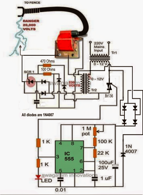
The above concept can be also implemented using a BJT for the generating the triggering pulses for the transformer, as shown below
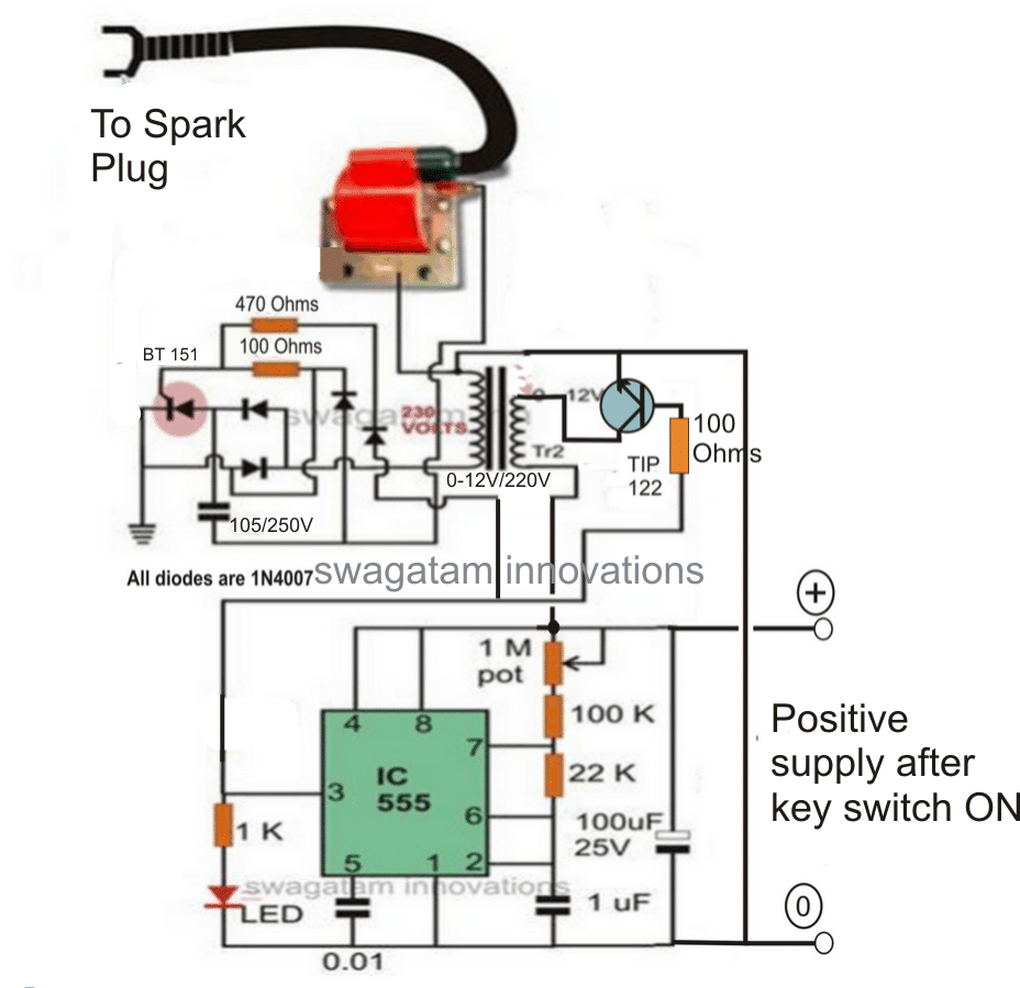
Please increase the TIP122 base resistor value to 10K for reducing increased dissipation from the transistor.
Adjust the 1M pot such the ON time of the IC 555 is much shorter than the OFF time, for reducing current consumption.
Video showing how an Ignition Coil could be applied for producing high voltage
Mini Fence Charger Circuit
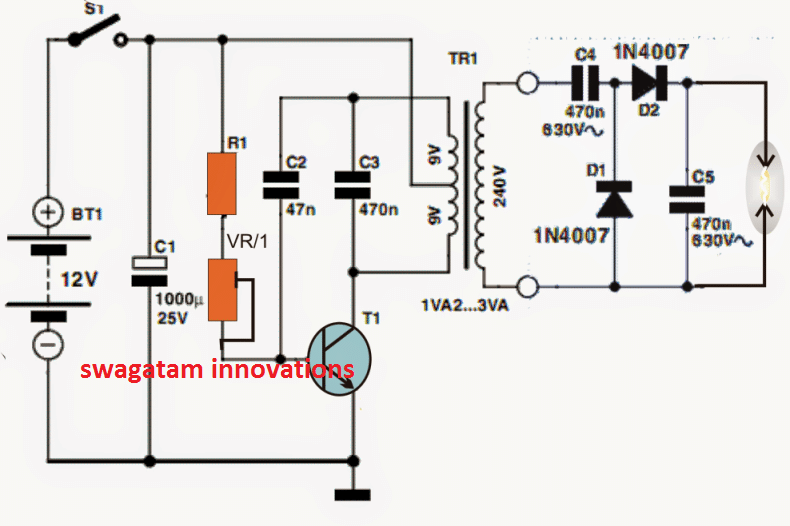
The discussed fence charge above is relatively lager and stronger with its specifications. If you need something smaller, then the following mini fence charger circuit can be quite handy.
This may be used for driving away pests like cockroaches, slugs, worms, snails from any desired small premise such a terrace garden, balcony pot plants or simply for guarding food stuffs etc.
Circuit Operation
The referred circuit for the mini fence charger is shown below, it may be understood with the help of the following points:
The top part of the transformer winding basically delivers a reinforcement to the base of the transistor by means of C2 the T1 keeps being confined on to the conduction status until C2 charges completely, ending the latch and compelling the transistor to commence the conduction sequence afresh.
R1 that may be a 1K resistor is installed to restrict the base gain for T1 to secure inhibits whereas VR1 that could be a 22k preset could very well be tweaked for acquiring an effectively pulsating T1 rate.
C2 could be additionally fine tuned by attempting supplementary values until the maximum output is accomplished at the trafo output
Transformer Specs
The transformer could possibly be any iron-cored step down transformer (500mA) commonly employed in transformer version AC/DC power supply devices.
The output immediately across the transformer output may be at the evaluated secondary level, for instance whether it is a 220V secondary, in that case the output could possibly be anticipated to be with this levels.
The above degree could possibly be even more heightened or stepped up by means of the connected diode, capacitor charge pump set-up corresponding to cockroft-walton power generator system.
The set-up boosts the 220V level to scores of volts that could be compelled to spark across an accordingly deployed finish terminals of the charge pump circuit.
The above end high tension end terminals could be appropriately wired up across the whole length of the area which needs to be guarded from the bugs and for implementing the intended fencing charging operations.
The fence charger wires must be separated by some minimum distance so that the sparks do no keep flying of even in the absence of any external intrusion from the insects.
The explained mini fence charger circuit concept could be furthermore utilized in mosquito swatter bat purpose by swapping the iron cored transformer with a ferrite core counterpart.
Circuit Diagram
Using 4049 IC
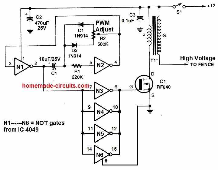
Since the above fence charger can operate with a 12V battery, it is a suitable option for remote locations which may lack an access to AC power.
An oscillator circuit is constructed using two NOT gates N1 and N2 from a 4049 hex-inverting integrated circuit.
It has a PWM control feature using the pot R2. This can be used to fine-tune the output PWM to optimize output voltage and performance of the fence charging.
The MOSFET switches to ground whenever the positive pulse of the input at Q1's gate is available, connecting the primary winding of T1 across the 12 volt source.
When the MOSFET gate signal turns logic low, the current between Q1 and the transformer's primary is inhibited. This causes a high voltage pulse to be produced through T1's secondary winding.
This causes a high voltage in the order of around 20 kv to be generated at the output of T1. This output can be linked with the fence for the intended electrification.
Remember, T1 can be any automobile ignition coil. We recommend using a two-wheeler ignition coil.
How to Setup
- Setting potentiometer R2 to its half way is the easiest technique to optimize output arc and circuit performance.
- Next, hook up a DC current meter in series with the circuit and power supply positive.
- T1's output is then positioned approximately half an inch above the ground line of the circuit.
- Finally, R2 is adjusted for getting optimum output voltage spark and lowest current consumption by the circuit.
Fence charger circuit using SCR and Ignition Coil
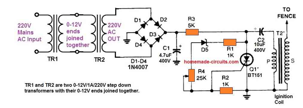
Another simple design of a fence charger circuit is shown in the above figure. This circuit is designed to work with a 220V or a 120V AC input. So, this circuit can be used only in places where an AC outlet is available.
The SCR along with the capacitor C2 forms a capacitive discharge circuit, which works with a 310V DC input.
The 310 V from a 220 V RMS input or a 170 V from a 120 V RMS peak voltage inputs is achieved through two step down transformers connected back to back.
TR1 and TR2 transformers are two 0-12V/1A/220V/120V transformers configured with their 0-12V ends attached together.
This allows the circuit to get a high voltage low current peak DC supply input for the intended capacitive discharge operations.
When AC power is switched ON, the 220V or 120V from TR2 is converted into the required high voltage peak supply via the bridge rectifier and the capacitor C1.
The peak DC passes through R2 and the primary side of the ignition coil until C2 is fully charged. When charged fully it develops sufficient voltage to switch ON the zener diode D5.
D5 now conducts and fires the SCR. The SCR triggers ON and discharges C2 through it. This instantly causes the stored peak DC inside C2 to suddenly pass through the ignition coil primary.
This in turn causes an equivalent high voltage in the order 20 kV to be induced on the secondary side of the ignition coil. This 20 kV generated output is used for electrifying or charging the intended fences.
Simplest Fence Charge using Just a Couple of Transformers
If you have an access to a 220V AC or 120V AC mains input within reach, then perhaps the following simple transformer based AC fence energizer circuit could be used for the purpose, without incorporating any kind of complex circuitry.
The low current 220V side can be used to energize the fence.
To increase the output voltage to 500V AC you can use a 0-6V / 220 V transformer for the right hand side transformer.
Also if you wish to increase the current capacity of the output you can appropriately increase the Ampere rating of the two transformers.

The capacitor may be selected depending on the level of electric shock needed for the application.
Note: Although transformers are used for dropping the input current to significantly lower levels, still the output from this system may be large enough to kill any living thing if it happens to get stuck or entangled in the fence and is subjected to the current for a longer duration of time. Please build it AT YOUR OWN RISK.
Another simple Fence Charger Circuit using Transistors
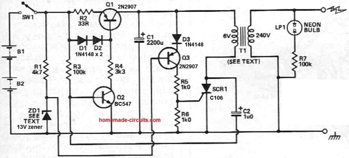
Capacitor C1 undergoes charging via a constant current facilitated by transistor Q1.
Zener diode ZD1 maintains the base of Q3 at 13V, enabling conduction through D3 as the capacitor's charge reaches approximately 14.3V.
The conduction in Q3 delivers the gate trigger to SCR1. Subsequently, C1 discharges through the modified 6V winding in the transformer's primary.
This action generates a high-voltage pulse at the circuit's output, which is linked to the fence.
The discharge of C1 eliminates the gate drive to SCR1, allowing it to turn off as soon as the current reaches zero.
Diode D3 prevents excessive current flow through the base-emitter junction of Q3, safeguarding against reverse breakdown.
The current is limited to the diode's reverse leakage current, ensuring the safety of the transistor.
Under open circuit circumstances, SCR1 turns off independently as the transformer experiences slight ringing, diverting current from Q1 away from SCR1 and towards C1.
However, this automatic turn-off isn't assured when the circuit is loaded. To guarantee reliable turn-off of SCR1, C2 and Q2 temporarily interrupt the current from Q1, providing time for SCR1 to recover.
A resistor and neon bulb combination provides a visual confirmation of the fence charger circuit's operation, eliminating the necessity of touching the output terminals.
The lamp flashes with each pulse of the fence charger, indicating its functioning.
The T1 transformer can be any ordinary step-down transformer, connected in a reverse fashion, so that it steps-up the 6V to a 240V output.
With over 50,000 comments answered so far, this is the only electronics website dedicated to solving all your circuit-related problems. If you’re stuck on a circuit, please leave your question in the comment box, and I will try to solve it ASAP!
In the “Fence charger circuit using SCR and Ignition Coil” .
Is there any reason why TR1 and TR2 can not be removed and just put a 1000-ohm resistor in series leading to the bridge rectifier ??
–
An additional option is a 1000-ohm resistor on the top line and a 1000-ohm resistor on the bottom line before going into the bridge rectifier ??
–
If you use resistors they will heat up a lot and also the current will not be sufficient causing very weak sparks at the output…
I am really struggling with creating a reflectometry design project to be used as Fault location for a farm.
But I want to do a prototype, can anyone please help out or referee to previously done projects.
Thank you.
Hi, I have not studied this concept yet, but if you can explain more on this regarding how it is supposed to work then perhaps I can help to design a suitable circuit…
Hi Swagatam,
many thanks for your response. I built the suggested configuration, using the already existing 9-0-9V transformer, with a supply voltage reduced to 9V. The circuit worked for a few seconds then it gave up. Apparently the transistor burned out. I have used a 2N2222 – is it too weak? Which type should I use?
Greetings from Germany
Ulrico
Thanks Ulrico,
Glad the circuit worked.
The transistor type will depend on the current rating of the transformer 9-0-9V winding. If it’s around 1 or 2 amps then you can use transistors such as TIP31, TIP122, TIP41 etc
If the winding current is above 2 amps you can consider using 2N3055 or TIP35 transistor.
Dear Sir,
I recreated the Mini Fence Charger Circuit, unfortunately without the expected success. Now I’m sitting in front of the device and have no idea where to look for the source of the error. Could you possibly give me a tip?
Thanks in advance,
Ulrico
Dear Ulrico,
 ?auto=webp&frame=1&width=1024&height=1024&fit=bounds&md=aa8aa47fc5ff5764c92a4ae01f459878
Troubleshooting your circuit may not be possible for me because I cannot check the parts and connections practically.
Instead I will suggest you a simpler design. please check this circuit and build it, it uses a similar configuration but is much simpler:
Please Build and check it, if you succeed, i will tell how to further step up the voltage
I have an electric fence but I would like to monitor the voltage through to an Ardino and either display on an LCD or use an ESP32 to send the voltage webpage or SMS on mobile phone network to alert if fence voltage is too low or if there is a fault.
What is the best way to measure high voltage around 5.5kV? Could I use a voltage divider cirucuit or use an opamp circuit?
Thank you
According to me a voltage divider is the best way to go.
Thanks for your reply. How do I ensure the current won’t damage arduino circuit?
You can use high value proportionate resistors, which could be in 100s of kohms or Mega ohms, this would drastically reduce the current. Just make sure to rectify the AC to DC appropriately using diodes.
Thank you. I worked out my voltage divider. Do the resitors need to be rated to a high wattage. Say my electric fence unit is a 2W or 5W system do the resitors need to be rated?
If I have a solar battery electric fence unit do I still need a rectify cirucuit to correctly rectify the AC to DC?
Since the resistors have very high ohm value they do not need to be high wattage type, they can be simply 1/4 watt rated. If your 5.5kv is a DC then no need to rectify the output from the voltage divider…
I am excited to find this site & page of fence charger builds. Owning a farm, fence control is a necessity.
I am interested in building the SCR design. Looks simple and straightforward.
I have 120vAC for input. Will it be at least 20kv output?
For comparison: I was using a commercial charger rated at 6.3+ joules, 13-15k no load output, and 50 mile range.
Would the SCR design build be as powerful or could you suggest a more powerful ignition coil that would beef it up?
Also can a potentiometer be installed somewhere inline to adjust the pulse interval?
TY for any help you can share on this?
I am glad you are enjoying the articles from this website.
Yes, the SCR circuit can be used with a 120V AC supply also.
The maximum voltage output from the above fence chargers is determined by the power rating of the ignition coil. A car iginition cpil can probably be rated to generate a very high volatge output.
A potentiometer might not work in the SCR circuit, you can tweak the C2 value to adjust the pulse timing of the output voltage.
Thank you for all the interesting circuits. I have a couple of questions about the SCR ignition coil circuit.
What is a 0-12 volt transformer? When I see this I logically think it means a 0 to12 volt variable transformer although the circuit diagram doesn’t show it to be variable. Also, can you tell me why you used two transformers when one isolation transformer would perhaps work?
Thanks
0-12V indicates that one of the wires of the secondary is 0V while the other wire is 12V, meaning the secondary side is basically a 12V winding and will generate 12V when the primary side is applied with a 220 V AC. Two transformers are used to generate a 220V AC at a very low current from the two transformers….a direct mains 220V AC could perhaps burn the circuit.
Hi. I built the “Fence charger circuit using SCR and Ignition Coil” The output is quite uncomfortable to touch but is not strong enough to produce an arc of more than a couple of mm. The input to the coil is a 20hz sawtooth of 50 volts p-to-p. Any suggestions?
Hi, If the sparks are a couple of mm long that means the voltage is around 2 kV or more, which is strong enough to work as a fence charger for many meters long fence wires. Make sure TR1 and TR2 are rated at at least 1 amp or more.
How can I use a 12v car coil with a flasher unit to stop dogs from going into my vegetable garden. Any ideasdor diagrams will help.
Instead of making a high voltage generator you can use a PIR sensor and a loud alarm to drive away the dogs.
PIR Burglar Alarm Circuit
Fence charger circuit using SCR and Ignition Coil, i want to know for D5 zener diode value? TQ for the answer.
It can be a 24V zener diode.
සිංහලෙන් කිව්වොත්, සුපිරි ????
Hi, I’m looking for a device that can be used against rats and snakes. Especially against snakes, the device should be strong enough. Electric shock and heat from sparks would be ideal. The conductors should be able to be glued to an elastic strip of approx. 10 – 15 cm, so that everything can be attached flexibly. Total length should be up to a km or more.
I would be very interested if you could build and sell me such a device, because I can’t find anything like that in Thailand. It could very well be that I will then order more devices, since there is a demand for such protection.
Thank you very much
George
Hi, I understand your requirement, but unfortunately it won’t be possible for me to build the units for you. You will have get it manufactured from an experienced electronics engineer. You can try any one of the 555 based circuits for your mentioned application.
Thank you for taking the time to address each & everyone’s concerns with their project. Not many people are willing to do this. I have a not-so-unique problem, unless you consider dealing with moose getting into your garden unique. Looking for a fence charger to output some substantial voltage 10k – 20k but powered with a lead-acid battery and have an integrated solar panel to provide a charging circuit for the battery. The battery size I have in mind are the 12vdc batteries found in most large trucks & heavy equipment. While there is substantial daylight during the summer months in Alaska, I would rather rely upon the lead acid battery to operate the fence charge. As for length of the fence wire, is it possible for the output of the charge to be sized to deliver enough power to a mile of wire?
Thank you, I am always glad to help!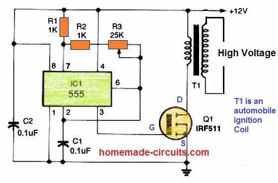
To generate high voltages above 20KV you can try the 555 based circuit explained in the above article.
For generating voltage in the range of 5KV you can try the following circuit
Yes you can use a 12V battery for th both the recommended circuits.
The output high voltage can be controlled to any desired lower levels by reducing the battery voltage proportionately.
I did review this project from earlier but the only question I have about it is the primary voltage supply. The circuit shows an AC voltage supply & AC transformer which cannot be used with the primary voltage being a 12vdc battery. I’m assuming an inverter of some particular size would have to be incorporated into this somehow and then there is the issue of adding in the solar panel to charge the battery.
Yes that’s right, since the CDI coil primary is designed to work with 100V to 220V AC inputs, an inverter will be necessary for 12V operation. You can try the first circuit from this article for the inverter design. Since current is low for your application, the transformer in the inverter can be replaced with a 1 amp transformer.
7 Simple Inverter Circuits you can Build at Home
The battery can be a simple 12V 7 Ah which can be charged with any 16V, 2 amp solar panel.
So I injected 1Vrms in the circuit. At 50Hz, I got 25V DC, wich seems like the right thing. At 5 Hz, it drops to 12.5 V DC. What could be going wrong? I put the diode in series with the capacitor and measured the Voltage on the capacitor.
Also, I’m worried that the transformer will saturate when working at the full 12V-5Hz, since the frequency is way lower than the transformer spec. Could that be the case? Thanks again for your support.
Yes it will saturate at higher voltage. Actually if the input pulses are sharp and short then the transformer won’t saturate. For example if you manually connect/disconnect the transformer winding rapidly with a DC source, how would the transformer react? It won’t saturate I guess.
Hi Swag,
So I breadboarded the whole circuit. Don’t have a 2 wheeler coil yet, so I put a 200k ohm load instead. Just to get it going.
It works. But, I get a very low voltage reading on my load on my oscilloscope, like 10V. Wich doesn’t make any sense.
I’m using a MKP capacitor instead of an MKT, because it was really easier to source where I am. Could it be a cause of problem? Since then, I’ve found a nearby supplier of MKT capacitor. Should I switch?
For now, I’ve set the pulse at 0.3 seconds and the down time at 0,7 seconds (with a diode parallel to R2). The transformer gets warm after 5-10 minutes of on time. Should I be worried about letting it run for many days?
Thanks for your support.
Hi Jean, the capacitor should be PPC or MKT type as shown in the following image. Did you confirm the output voltage from the transformer secondary? Unless you have the transformer, the CDI circuit and the ignition coil correctly configured, judging the final results can be difficult. So I would suggest you to get all the components and then check the final results.
If the transformer warms up slightly, it is quire normal, but this should happen only once the ignition coil starts arcing.
Thanks for your answer. I’m on my first year of my bachelor in Electrical Engineering and I love coming here to learn new things. Your blog is really an inspiration for me.
When I insert 1Vrms at 50 Hz in the transformer, it output (on my amprobe multimeter) 19V, wich seem normal. When I lower the frequency to 25 Hz, I get 15 V for the same input voltage. Then when I lower again the frequency to 5 Hz, I get a 6V reading on my multimeter.
Is it because the multimeter isn’t made to measure such low frequencies?
You are welcome! I am glad you liked this site!
Can you please confirm the peak voltage output. You can connect a 1N4148 or 1N4007 diode and a 100uF filter capacitor with the transformer output and check the output through a DC voltmeter. I guess the peak voltage will be the same for all the frequencies, it s only the RMS voltage that may be changing with frequency.
Hi Swagatam,
I found a 12-220V 50Hz transformer on Ebay for the project (SCR circuit). Then I realized the transformer frequency is way too high compared to the frequency of the circuit (1 to 5 Hz).
Will it still work with the transformer I found? (I guess not), where can I find a transformer for such low frequencies?
Thanks for your support, you’re a machine! A new circuit to look at every 2 weeks is incredible!
Thank you Jean, the 50 Hz probably indicates its optimal frequency range, beyond this range the transformer may heat up, but it does not mean the transformer cannot handle a low frequency of 1 to 5 Hz. So you can definitely use the 50 Hz transformer for the above application. In fact the transformer that are shown in the diagrams are all 50 Hz iron core transformers.
Hello sir,
The last circuit “Simplest Fence Charge using Just a Couple of Capacitors”, can only one wire be connected to fence ? Single stranded.
Hello Ganpati, yes that’s possible…you can use the LIVE wire with a series 0.01uF/400V capacitor. Lower capacitor values will ensure that the animal is never killed due to severe shock. Also make sure that the fence is not grounded, otherwise the current will become ineffective.
Hello Sir,
which circuit diagram should works?? confusing please help.
Hi Shripad,
all the circuits will work….the last diagram is probably the easiest, which you can build quickly
Hello Swagatam! You have some nice solutions here, but the schematics could be a little more readable, especially when it comes to the high voltage section with diodes. It is very hard to see exactly what’s going on there. I basically have to re-draw it for myself in order to get a clear picture. The components are thrown around and then connected whichever way possible.
First rule that will help you is to abandon the curved line where conductors/lines intersect. That practice is outdated because it slows the drawing down and it is less clear what goes where. The new standard calls for straight lines at crossing points and dots where they connect. So, no dot – simple crossing without connection, dot – the crossing lines connect.
Second rule would be to keep the lines straight between endpoints, and avoid zig-zag or multiple bends between two points. You can achieve this by either moving a component until a line is straight instead of bent, or rearranging components so there is no need for “creative” re-routes.
Greetings from Bosnia!
Thank you Edin for your valuable suggestions, I agree with you and I am aware for these facts in my diagram. I have basically used the curves at the intersections just to make sure that the newcomers don’t get confused and get a clear idea regarding which lines are actually connected and which are not.
I would like to know if you can tell me how to build a DC electric fence energizer to protect my Bee Hive from bears? I have seen them using a car old style ignition coil, but do not know if they are powerful enough to discourage a bear. Thanks for any help.
You can try the concepts presented in the above article. All the concepts are built using an automobile ignition coil, which are extremely powerful and can deter even an elephant.
my zareba fence charger has a 50uF+/-5%,.420 volt capacitor
is this the same type of capacitor used in a well pump?
I am a lIttle concerned about killing someone with electric fence but have had it for 40 years.
Yes they can be the same capacitor, if the values printed are the same.
The last circuit in the article will not kill any animal. Still you can further reduce the capacitor values to 0.1uF/400V to make the shock milder.
Dear Swagatam,thank you for your wishes,i almost feel beter and i’m waiting to pass the quarantine period. By the way, if you know can you suggest me any open source drawing program for prinding on boards? This will very helpful for me. Regards John.
My wishes are always with you John, and we are glad to know about your speedy recovery.
I think if you Google the phrase “pcb drawing online”, you might come across a few good PCB design softwares
Good morning from Greece, ( is 7:30 p.m is here!!! )I must first of all to thank you for your quick response to my questions, i appreciate that.But my problem is now that i’m in covid-19 quarantine to my house and i can’t do nothing!!! It it pass by the good way i will check out your changes. Thank you once more,John.
You are most welcome, and wish you a happy and a quick recovery!!
O.k. i will see about that, and i think maybe the cdi transformer is more heavy from two wheelsand not from chainsaw this may cause the Tip122 heating. Finally the project i need it for an area about 120 square meters with 3 lines coil ( to keep safe my bees ) will it cover it? What do you think ? Regards John.
It will cover 120 sq meters if the CDI coil is a strong enough, you can try a car ignition coil and that should do the job…
The CDI coil and the transformer both will need to be heavy duty, and the TIP122 could be replaced with a TIP142.
Good afternoon from Greece, well as i say before the base resistor it is already 10k and the transformer specs is 220v/12v/1A 50/60 hz. Do i need to replace TIP122 with one other stronger one( more than 5A)? What do you think? Yours John.
Yes lower base resistance will allow higher current through the transformer and therefore brighter spark, but that will also cause the TIP122 to be hotter. If your DCc supply is 12V and the transformer is also 12V/1A then TIP122 should be OK with a large heatsink, however if you want to avoid the heatsink, then you can replace the TIP122 with TIP35 or TIP3055.
Dear Swagatam good afternoon from Greece, my name is John and i’d like please to ask you for the fence cirquit this: i made the project and works fine exept the TIP122 is getting hot at once.The bace ressistor is 10k and ic555 between 6-7 22kwith 1M pot above.Any idea why this hapent? And finally you don’t give any prindable board diagramm and was for me very dificult to righ placing and connecting the parts together. Thank you for your answer replay, yours John. P.S. I place and a heatsink on.
Dear John, try a 10k resistor at the base of TIP122, and you will have to put the transistor over a large heatsink.
By the way what is the transformer rating that you have used? If the transformer is big then the TIP122 will heat up more…try using a smaller transformer.
can reduce the frequency to 1Hz
yes you can.
Dear Sir
If the area of the farm is about 50000 sq. meter, can this fence circuit be built with the same components so it can produce enough shock to avoid wild animals from entering the farm. If you have alternative circuit would you mind send it to my email. mes.mhz@gmail.com.
thank you for kind help.
Mohammad
Hi Mohammad, I don’t think this can power the whole 5000 sq m area. However, you can install a single unit across every 200 sq meter distance to ensure the whole area is optimally secured.
how many meters of fence does it energize?
20 meters
Dear sir
Thank you for your kind response. Do you advice any product to protect the farm from wild pigs. Or if you have a certain circuit diagram so you can build it or I can build it to protect a fence of 800 meter. Please send me addresses if you have. Great thanks for you.
Best regards
Mohammad
Mohammad, you can try siren sound method which will activate when an animal nears the fence. You can put many such sirens across different corners of the fence for the operation. Each module could be operated with battery, charged from a small individual solar panel.
Hello sir …how can I reduce output current to 9mA or less?
Shubham, you can reduce the 105 capacitor to some lower value….
Hi, can TV flyback transformer be used instead of car ignitor for distance of 2 feets squared, and if it can work, do you have a circuit diagram for it ?. Can tv flyback tx kill small animal like squirrel?
Hi, it can be used and it will kill small animals so it’s not recommended. Even current from an ignition coil can kill small animals…I have this circuit in one of the electronic magazines that I will try to update it.
what is the best Jataka machine diagram can i get Gerber file on net
can you please tell me for what purpose you need it! It’s required to know the power specification of the circuit
Hello, I need your help
I have assembled an Electric fence energizer from a commercial kit and it works perfectly with an old car ignition coil.
https://www.pinterest.es/pin/311241024245287787/
https://www.pinterest.es/pin/311241024245287671/
The problem is that it ends with a 12V-7.2Ah / 20hr battery in less than 24 hours.
https://www.pinterest.es/pin/311241024245287726/
And it is the same battery that feeds another Electric fence energizer of industrial manufacture for 3 weeks.
Can any of you tell me how to reduce the consumption of this assembly?
Hi, you can try increasing R2, R4 to 470 ohms, or upto 1K.
and decrease the value of the 33uF to 22uF or 10uF.
Please check the results and let me know!
Hello, I appreciate your quick response.
Now I am traveling, when I return I will make the changes you recommend.
I will expose the results in this way
OK, great!
Hello again,
I have made the changes you suggested and the results have not been as expected.
When I decrease the value of 33uF, electric discharges are accelerated and consumption increases. I have tried to increase the capacity to 100uF and the electric shocks decelerate a bit, but the consumption does not decrease much.
With the resistors I have increased its value up to 1K and, contrary to expectations, the electrical impulses have increased a lot.
I do not understand the behavior of the circuit.
I do not know what else to do
Anticipated thanks
Hello,
referring to this diagram:
the circuit is a simple transistorized astable multivibrator where the two transistor sides oscillate alternately with a delay time determined by the values of R1/R3, and C1, C2, …or simply all the 4 components combined decide the ON/OFF intervals. Higher values will give higher pulse delays and vice versa.
To avoid confusion it is better either to change C1/C2 or R1/R3.
When the values of these components are equal on both sides then the pulse delay time is equal on both sides meaning we get 50% ON/OFF timing across the two transistor collectors.
But suppose if you increase or decrease either C1 or C2 will result in the pulse delay across the transistor collectors to change and become un-uniform.
In other words one of the transistors will produce narrow pulses while the other transistor will produce wider pulses.
Narrow pulse will allow short switching time of the transformer and therefore low battery consumption and also weaker sparks, while the wider pulses will cause higher consumption and stronger pulses.
So you have to identify with trial and error reducing which capacitor reduces the pulse intensity. Keep testing with reduced values until you identify the right consumption value.
And increasing R2/R4/R5 values will definitely help to reduce the overall consumption because in doing so the switching current through T1, T2, T3 will reduce proportionately.
Since T3 inverts T2 pulses, adjust one of the capacitors such that T2 gives wider pulses, this wll cause cause T3 to conduct more and reduce T4 conduction and help to reduce the battery consumption.
If someone had a circuit that does the same functions but with a reduced battery consumption, I would appreciate it very much.
Greetings and thanks again
Hallo sir, i want to make a flying insect killer from your mini fence charger circuit. so please suggest me which type /model/number ferrite core transformer should i use in that circuit ,instead of iron core transformer?? what are the values of c2,c3, c4 and c5 . does the c4 and c5 are ppc one ? thanks in advance
Bhanu, the concept presented in the following link will perhaps fulfil your specific need:
https://www.homemade-circuits.com/mosquito-swatter-bat-circuit/
thanks a lot for your quick response!
Sir, in above mentioned mini fence charger circuit, what is the value of the TRANSISTER “T1” ?
You can use 2N2222, 8050 or TIP31, or D1351
hi…
if i need to get 8kw from this ciruit, what kind of changes has to be done?
Thanks
8 kv
Hi, you will have to build a custom transformer, and use mosfets for triggering the primary of the trafo. It will be like a 8kW high frequency inverter circuit
I made a fish shocker using a ign coil which lead do I let grag the lake bottom
obviously it’s the high tension cable from the ign coil block which you should use for the shock.
Hello sir,
With the DC Circuit how much area of the farm can be covered? maximum?
Hello Bharghav, you will have to test it practically, it will be difficult to assume it..
Thank you for your advice.
Regards
Jan
Hi Swagatam,
In my country we have a huge problem with armed car hijackers. I want to know if I can install your unit in a car so that it can be activated when you are high jacked. I want to connect it to the chassis of the car so that when the hijackers touch the car they will be shocked by the high voltage. Hopefully this will deter them and they will seek easier targets.
Do you think this can work? I am especially concerned that high voltage can cause a spark in the fuel tank of the car.
Kind regards
Jan
Hi Jan,
I am afraid that may not be possible, because the car body is huge and this might make the impact very weak, and even if it was made strong it can't affect the intruder since the intruder would be wearing shoes, and without an earthing the shock would become ineffective, so the concept won't work as assumed by you.
and yes the fuel tank is another crucial thing which might need to be considered…
The charger design discussed here is not considered low-impedance output is it? If I understand correctly, a low impedance current would have a final transformer with a low ratio winding.
Hi, is there any place to buy this as a Electronic Kit? Thanks
Hello Swagatam,
The circuit works,But,
1)The output pulse length is short,if adjust the 1M pot.
2)Not work with 12v Dc Battery.
Pls help me.
Thanks.
Hello Thushara, the circuit will definitely work with a 12V battery but make sure it's rated at, at least 7 ah
for increasing the pulse length you can try increasing the 1uF capacitor to 10uF and see the difference…and also replace the 22K resistor with a 100K pot so that you get an additional option for optimizing the PWMs
Hello Swagatamsir
I want to add siren with this circuit for fencing use to protect my farm …. When wild animal touch wire I want to blow the siren ….plz help me
My mail id Sanjaybharvad138@gmail.com
Hello Sanjay, the siren will need to be configured separately by using some other concept such as through an IR based alarm system or a vibration detector etc…It cannot be done within the above explained circuit…
Ok, I will give I try. But beside this car bobbin everything seems to be clear to me .
Thank you!
sure! wish you all the best
Thanks Swagatam, one more question, the high voltage bobbin I have has primary with marks 15 and -. The secondary of Tr2 going to one primary of the bobbin I suppose to + (15). From SCR , end going to minus (-) and earth of fence. End of C4 going to bobbin secondary. The other end of secondary bobbin going to fence(high voltage). My bobbin is from a car, and has short with one end of primary and one end of secondary. Will this work in this way?
Sorry Bursach, I am not quite able to figure out your trafo specs from those markings.
I think a relatively easier schematic is discussed in the following article which you can try with less difficulty:
https://www.homemade-circuits.com/2013/01/make-this-enhanced-capacitive-discharge.html
you can try the first diagram
yes the SCR left pin will go to the ground
end of C4 is going to the primary pin of the ignition coil
If you are using a car ignition coil, then probably you could take the help of the diagram presented in the following article
https://www.homemade-circuits.com/2015/03/making-strong-rf-discharge-circuit.html
I think these are ordinary transformers but compact, check this link, what I mean :
http://www.kelco.rs/katalog/detalji.php?ID=6928
I think these Tr are not ferrite.
yes, these can be used!
Thanks Swagatam, I suppose 2×1.25A= 2.5A for Tr1 with 30VA and 2x12V will be enough ?
The specs for both the trafos could be approximately 0-12V/1Amp/220V
Ok, I will make my own. Can I use for example Myrra transformers to montage to pcb? The second Tr I have is 2×1.25A, is it sufficient or it has to be just 3A?
The transformers are ordinary step-down iron core type since these are supposed to be used with the 50/60Hz from the mains, ferrite versions will not work
Hi Swagatam, is there any PCB for both circuits?
Hi Bursach, sorry no ready PCB designs for the circuits
sir give ur number pls
Sir, since the output voltage we get is in pulse how can we measure output voltage?
Gom, 20kV can be difficult to measure with ordinary DMM….but it's not required…you can judge it visually…if the spark is able to fly across a 1cm gap or more then it's well over 20KV