In this post I have explained a simple IR based remote controlled night lamp timer circuit. The idea was requested by Mr. Raj Kumar Mukherji.
Technical Specifications
Please provide the component values and the modified circuit if:
a. the circuit is made to work from 4.5 volts or 5 volts
b. the relay is replaced with a 5mm LED
c. the circuit is triggered by TSOP1738
d the delay time is set for 2 mins max
This is for an old person in my locality. He wants a low cost portable light which he would turn on
remotely for a brief period at night and the light would get turned off automatically. He has to get up at night to drink water etc and he does not want a night lamp to be on the whole night or to operate one from the mains power. The best idea that came in my mind is to use the transistorized timer circuit in combination with a TSOP1738 and using 2 or 3 AA cells.
Thanks and regards,
Raj Kumar Mukherji

The Design
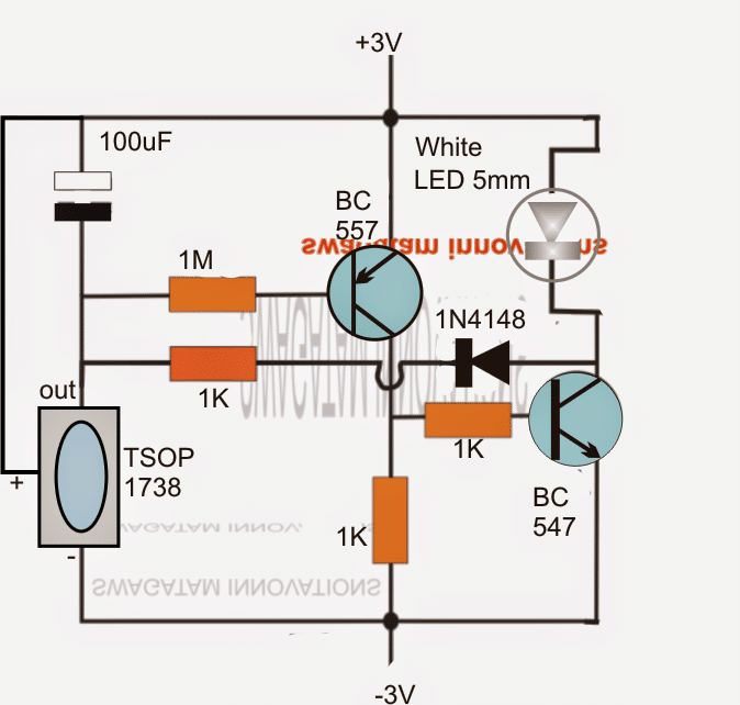
The proposed remote night lamp timer circuit can be visualized in the above diagram and understood with the following points:
The IR sensor TSOP1738 responds to an incoming IR signal from a suitable IR handset such as a TV remote or similar, and produces a logic low at its pin labelled as "out". The directed Tx signal could be momentary, probably for a fraction of a second for initiating the triggering response in the circuit.
The above action instantly charges the 100uF and also switches ON the BC557. This correspondingly turns on the BC547 and the LED.
The stored charge sustains the switched ON position for a certain time period determined via the selected values of the 100uF capacitor and the 1M resistor. These may be altered, experimented for acquiring any desired time delay for the LED illumination period.
The 100uF slowly starts discharging via the 1M resistor and the base/emitter of the BC557 until it becomes too low for the transistors to hold the conduction, the LED consequently is also switched OFF as soon the RC determined time is elapsed.
The 1K and the 1N4148 diode ensures a complete discharge of the timing capacitor 100uF each time the LED is switched OFF, so that the new cycle is able to begin with a correctly discharged capacitor, for executing consistent time delays, with minimum errors.
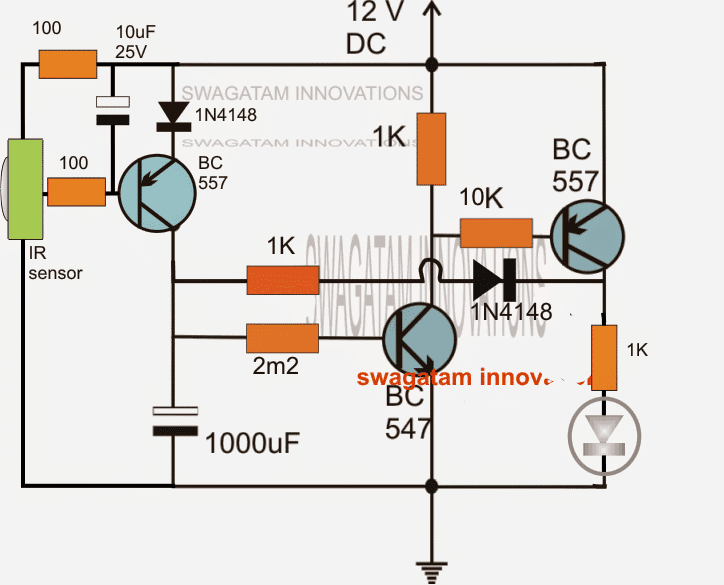
The above design can be upgraded as shown below for getting improved response:


With over 50,000 comments answered so far, this is the only electronics website dedicated to solving all your circuit-related problems. If you’re stuck on a circuit, please leave your question in the comment box, and I will try to solve it ASAP!