In this post I have explained a simple yet very useful 0 to 50V dual power supply circuit which will enable a full 0 to maximum dual voltage +/- control of the input power supply DC. It also includes a wide range current control feature right from 0 to 10 amps. The idea was requested by Mr. Tamam.
Technical Specifications
It was my long term dream to build a 2 channel power supply for personal use, I have seen a lot of circuits, but those does not fit my criteria.
However, please take a look at the following requirements and let me know if its possible or not, if possible I will be the happiest person in the world.
1. Output voltage range: -50V to 0V to +50V ( must be adjustable by individual channel )
2. Output Current range: 0A to 10A ( must be adjustable by individual channel )
3. Output would be Duel channel, means total 6 outputs,
Channel 1 (Positive, GND, Negative) Channel 2 (Positive, GND, Negative)
4. Power Supply Unit should contains 2 Voltmeters and 2 Ammeters (Analogue) for 2 individual channel.
5. Power Supply Unit must have short circuit protection and cooling fan featured and extreme heat protection.
6. I don't want to use any PIC or AVR, so please avoid those.
Money is not a matter here, I will spend continuously until above requirement meets.
Even If I need any custom transformer I will order and make it from our local area.
I have seen many ready made power supply in market but I want to make it by own hand. You just show me the way... please bro, I will be pleased to you for lifetime.
Thank you very much !!
Best Regards,
Tamam
For calculating the part values accurately, you can refer to this bench power supply article
Circuit Diagram

The Design
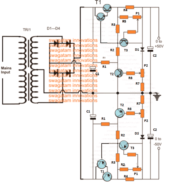
The basic design of the proposed 0 to 50V variable dual power supply circuit with 0 to 10 amp variable current facility is shown in the above figure.
The entire design is transistor (BJT) based and is virtually indestructible. Moreover it's equipped with an over load and over current protection features.
The two section included in the design are exactly similar with their configurations, the only difference being the use of PNP devices in the lower configuration while NPN in the upper configuration.
The upper NPN design is configured to produce a variable response right from 0.6V to 50V positive while the lower PNP section becomes responsible of producing an oppositely identical response from -0.6V to -50V output.
The Transformer Specs
The maximum limit could be suitably changed simply by changing the voltage rating of the transformer. However for higher voltages you may have to appropriately upgrade the BJT voltage ratings accordingly.
In both the designs, P2 executes the function of varying the voltage levels as desired by the user, while P1 functions as the current regulator and is used for adjusting or setting the output anywhere from 0 to 10 amp current. Here too the maximum rating depends on the selection of the transformer amp rating and may be changed as per individual preferences.
T1s in the both the sections become the fundamental part or the heart of the entire voltage control functioning in the circuit, which becomes possible due to the popular common collector configuration of the devices.
The other two active BJTs only help to implement the same just by controlling the base power of the T1s thus making it possible to adjust the thresholds to any desired user defined voltage and current levels, as per the ratings of the transformer or the input supply.
You may also like this LM317 based Dual Power Supply Circuit
Parts list
- R1 = 1K, 5 watt wire wound
- R2 = 120 Ohms,
- R3 = 330 Ohms,
- R4 = to be calculated using Ohms law, R = 0.6/Maximum Current Limit, Wattage = 0.6 x Maximum Current Limit
- R5 = 1K5,
- R6 = 5K6,
- R7 = 56 Ohms,
- R8 = 2K2,
- P1,P2 = 2k5 presets
- T1 = 2N6284 + BD139(NPN), 2N6286 + BD140(PNP)
- T2, T3 = BC546 (NPN) BC556B (PNP)
- D1, D2, D3, D4 = 6A4,
- D5 = 1N4007,C1, C2 = 10000uF/100V,
- Tr1 = 0 – 40 Volts, 10 Amp
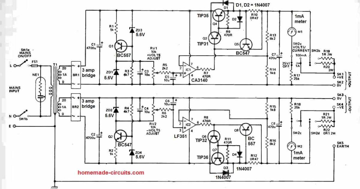
Using Op Amps and TIP35
Here's another accurate adjustable dual power supply circuit, for your reference:
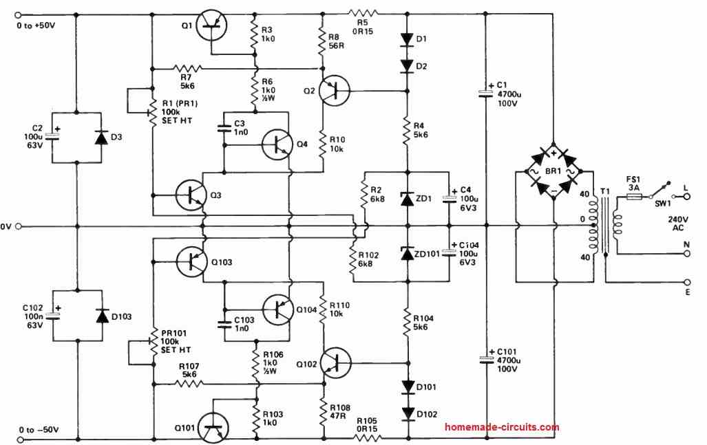
Using MJ2501 and MJ3001
The versatile dual power circuit featured here can supply a maximum of 50 volts across its two output rails, capable of handling currents of up to 3 amperes.
To support these output levels, the secondary of T1 should have a rating between 4.5 and 5 amperes. Furthermore, it includes comprehensive current limiting protection.
This circuit is well-suited for applications involving audio power amplifier modules that demand supply rails of up to 50 volts. Please take note that R8 should be set at 47 ohms.
NOTE:
Q1 IS MJ2501
Q2, Q104 ARE BC448
Q3 IS BC182
Q4, Q102 ARE BC447
Q101 IS MJ3001
Q103 IS BC212
D1, D2, D101, D102 ARE ANY GENERAL PURPOSE SILICON DIODES
D3, D103 ARE 1N4002
ZD1, ZD101 ARE 5V6 400rnW ZENERS
BR1 IS 600V 10A BRIDGE RECTIFIER
With over 50,000 comments answered so far, this is the only electronics website dedicated to solving all your circuit-related problems. If you’re stuck on a circuit, please leave your question in the comment box, and I will try to solve it ASAP!
Hi mr. Swagatam.
I have a problem with making an overload / short circuit protection for a dc-dc buck converter output.
I want to make a bench power supply but this buck converter with lm25116 control ic, it dose not turn off the output in short circuit or overload conditions and this causes a damage to the output mosfets.
The input voltage is 26v.
Te output voltage is 1v to 25v and the current is 0.1A to 15A.
The dc-dc buck converter is 300w 20A.
Help me with a proper overload / short circuit protection circuit.
Hi Talal,
The LM25116 IC has all the voltage and current control features available in the IC.
You have to configure a current sensing resistor in series with the source pin of the low-side MOSFET, and then connect the junction to the CSG pinout of the IC.
Full information can be obtained from the following pdf:
https://www.ti.com/lit/ds/symlink/lm25116.pdf?ts=1722424800958&ref_url=https%253A%252F%252Fwww.google.com%252F
Hi swagatam What you thinking for output 20 amper give circut design also ıts give adjustable voltage.
Hi Enes, 20 amp is too high and is not recommended for this type of circuits due to high heat dissipation.
Hello Swagatam . I want to make a 0-60V 20A regulated power supply, can I provide this in the circuit you have given?
Hello Inesta, as we all know the biggest drawback of all linear regulator power supplies using transistors as explained above is high power dissipation, which is proportional to the difference between the input and the output voltage levels.
So at 20 ampere the heat generated on the transistors will be immensely high at low output voltage settings, therefore I cannot recommend you the above design.
Hi.. swagatam
I will like to build this power supply +-50v 0-10amps
* Can I Change the variable resistors value to a common value like 5k or 10k ? Will they be any effect when done?
* How can MOSFET be used in this circuit how do I use it?
* will they be any effect?
Hi Davis,
The variable resistors can be replaced with fixed resistors after calculating their values appropriately.
You can replace T1 with MOSFETs, however if a MOSFET the minimum output will not be lower than 8V. Make sure to put a 12V zener diode across gate and source of the MOSFETs.
MOSFET will allow higher current output compared to BJTs.
Ok, I mean can I use a 5k or 10k variable resistors for both P1 and P2 instead will they be any effect on the voltage or current? Because it will difficult to get 2k5 variable resistors here in my electronic store.
Using MOSFET could have been better but since you said it minimum output voltage can’t be less than 8v then I think I will just go for the BJTs
But can’t it be 4v minimum because of it gate voltage? What if I use 6v or 4v zener diode?
Yes, you can use 5k potentiometer in place of the 2.5k, although the adjustment range might not be from start to end of the rotational dial rather might end somewhere in the middle of the travel.
Sorry, it is actually the maximum voltage that might be 6V lower than the maximum input supply voltage, meaning if the maximum supply is 50V, then the maximum output that can be achieved using a MOSFET will be around 50 – 6 = 44V
Ok,that makes sense now using FET, but will the voltage be 0v when voltage knob is turn down to 0 ?
If I will be using FET in place of BJT how will it be connected ? and what resistor value should be at the gate and gate to source
How do I connect FET?
Yes, almost 0V should be achievable.
I think you can modify the second diagram as explained in the following article:
https://www.homemade-circuits.com/0-300v-variable-voltage-current/
Okay…
If I will be using FET in place of BJT how will it be connected ? and what resistor value should be at the gate and gate to source
How do I connect FET?
Please see the second circuit as given in the previous link. You can build the same design for fulfilling your requirements.
Dear Sir, In the 0-50V dual PS, where do I take connection for the Digital volt(100v) and amp(0-10A) meter? size:48x29x21mm
Hi Parthasarathy,
you can connect the voltmeters parallel with C2 capacitors.
You can connect the ammeters, one in series with the + output and the other in series with the – output of the power supply.
Very kind of you.
Mr Swagatham,thank you for the post.I have assembled the circuit on a breadboard and was able to regulate volatge as well as current.However,not able to reduce the volatge to zero and current also to zero.Lowest voltage achieved is 1.4volts and lowest current possible is 80 ma.by tinkering the values of R5,R7,R8 some reduction is possible but not down to zero..By also removing the diode D1 and shorting T3 emiiter with P2,the lowest voltage can be reduced to 0.7 volts.Why do you need diode D
Thank You Vedamurthy, Glad you could make the circuit successfully.
D1 is positioned to ensure a minimum output voltage of 1.5V, which is in most cases quite low.
However, if you want it to be 0V, you can replace D1 and R7 with direct wire jumpers.
Current will depend on R4, so you can increase this R4 value to a level which causes the output to shut-down even at currents as low as 1 mA
Please let me know if you have any further questions.
Thanks for the reply.The lowest current of 80 mA was achieved for a R4 value of 39ohm(5W).However as the value of R4 is increased,the lowest current range can be lowered but it also reduces the maximun current range.At lower values of R4(less than 1 ohm),current control is somewhat impossible.Even after replacing D1 and R7 with jumper wires lowest voltage obtained is 0.9 volts.Also at a minimim voltage setting of 3 volts,the circuit draws a quiescent current of 20 mA which is otherwise zero above 3 volts..all these observations are pertaining to the circuit assembled on a breadboard.Hope i will get better precise reading for a soldered circuit .
Actually R7 is not relevant to the 0V output, only D1 is relevant.
The problem is that, even if D1 is shorted, T2 would still require around 0.7V to conduct, therefore the output has to reach 0.7V or slightly higher in order to enable T2 conduction and the control, so perfect 0V may not be feasible.
For the current variations you can perhaps try using selector switch for selecting the desired maximum or minimum output current limit range. Yes, being a high current linear regulator the quiescent current intake will be on the higher side.
Thank you for the reply.Appreciate you time and effort.
You are welcome…
Hello,
I got 50V / 800W toroidal transformer, interested in building adjustable linear power supply ( is it possible 0-50V / 16A ?)
Regards
Hi, Yes it is possible, however at 16 amps the power devices can dissipate a lot of heat.
Hello jonney I have a 28v± power supply .I want to reduce it to 18v± supply .can I use this circuit .if isnt what are the variations of this circuit .thank you very much .
You can do it using the above the circuit. No changes would be required.
Hi, Swagatam. I Want to know the value of the base resistor at T3 since i cannot see it. Thanks.
Hello Johnny, it can be a 1K 1/4 watt resistor. R5 can be eliminated, it is not necessary.
Thankyou so much, my man !!! You truly are one in a million. Now i can proceed with this project. God bless.
You are most welcome Johnny!
Consulta, si cruzo las puntas, la fuente sigue inyectando corriente?
If you short circuit the output, the output will continue to supply current as determined by R4.
Hi sir
I have to increase voltage. From 50v to 60volt. What i have to change in cercuit.
Pleace give a replay
Kind regards
Ashtaman
Hi Ashtaman,
The output voltage depends on the input voltage. if you use around 62V at the input then you will get around 60 V at the output.
Thank you very much sir
You are welcome!
hello, first of all, thank you for this post.
I have a question. please help me. I want to make an adjustable power supply circuit with a voltage between +-20 to +-50 (dual output) with low noise in the output. what do you refer to me?
thanks.
Hi, I can recommend you the circuit which is explained in the above article. However, I am not sure whether it has a low noise output or not.
Q1 :
In above Using Op Amps and TIP35 circuit tbere are 2 output pair first named as +output (+ & 0) and second named as (0 & -) . can we connect 0 of +output & 0 of
-output to create + , 0, – supply.
==============
Q2:
In above Using Op Amps and TIP35 circuit, transformer has 2 separate winding but can i use centre tapped transformer ?
or can we create opAmp based variable Dual
bench power supply s above using centre tapped transformer ?
Yes, you can connect the the two 0V lines to create a common 0V supply line.
You can also use a center tapped transformer and configure a common ground line, exactly as shown in the first diagram, using transistors.
Thnks a lot Swagatam for quick & prompt reply. some more clarification if that is fine for you.
I have two old pcb boards of 0-30v/3A and 24-0-24 centre tapped transformers. and both has bridged rectifier so I believe it is not possible to connect 24-0 winding of transformer to one board & 0-24 other winding to another board. As seems 2 bridge rectifier with centre tapped transformer create short in one of sine wave cycle (And also seen that in all above dual PS design used single bridge). Please correct me If this is wrong. And also please suggest if you have any idea to overcome this limitation.
Thank you Jaival,
I think what you are saying may be correct but simulating the situation in mind is slightly confusing, but it is better to avoid using a common center tap for the two boards.
The only two ways I can find is, one by breaking the center tap wire into two, so that the two 24V winding are fully separated, or use a single 24V winding for both the boards.
Thanks Swagatam for the idea.
First one if able to break the center tap wire of the transformer (Need to check its feasibility) then be able to create a full capacity of Power supply each one 0-30/3A capacity.
And the second one is easy but its current capacity is half of the first one. (Am i correct??)
Thanks again for the same, will check feasibility and go ahead.
No problem Jaival,
You can definitely try those options and see which one is more feasible to you.
Yes, you are right, if you use the half winding for the two boards, then the input current will be divided by half.
Hi, Swagatam. I would like to know where to incorporate my ammeter(s) in the above 50v psu.I do have all the components ready to start.
Regards.
Hi Johnny, you can connect the ammeter in series with the positive output lines of the power supply circuit
Wow! You are an amazing man. Its been so long since this was published and you stil reply to questions about it and so quickly at that. Thanks, man. May you be blessed.
No problem!! I am always glad to help!
Hello, I am very happy and thank you very much for this design of the laboratory source, it has all the parameters that I have been looking for for a long time. And I would like to ask if it would still be possible to make signaling using LEDs of constant current and constant voltage? If so, how?
Hi, thanks, and glad you liked the post.
LEDs cannot be used to indicate CC/CV. You will have to use a voltmeter and ammeter to confirm those parameters.
You can also refer to the following article for getting information on a related topic:
How to Design a Bench Power Supply Circuit
Good morning, are P1 and P2 potentiometers to regulate de tension an current needed? If yes, is it ok to use 50k pots?
thank you
P2 are for regulating the output voltage, P1 are for regulating current.
Hi Swagatam sir. first of all, thank you so much for your innovative ideas and sharing your knowledge with us. I really enjoyed your circuit and all those details you have provided. you are the only one who can help me, and ill be grateful if you manage some time for me.
As an electrical engineer, I always wanted a professional lab bench power supply. i have googled many times but none of those circuits fulfill my needs. anyways please take a look at my requirements and if it is possible please teach me or us how can it be done.
1) input :- 70v 11 amp dc ( i have such a transformer 35-0-35 ac )
and I want its output to be regulated.
2) v output :- 1.5 – 70v variable dc voltage.
3) I output :- 0 – 11amp variable current.
4) short circuit protection
please sir you are my only hope.
thank you in advance
Rahul.
Thank you Rahul, I can definitely help you.
You can refer to the following post for understanding how to build a bench power supply with all the required specifications.
You can try the 5th schematic from top:
https://www.homemade-circuits.com/how-to-design-a-stabilized-bench-power-supply-circuit/
However, being a linear power supply the transistor can heat up a lot at lower output voltages. To prevent this you will need a transformer which has tapping after every 12V. So it should have voltage tapping at say 12V, 24V, 36V, 48V, 60V, and 70V. When the output load is below 12V, you can select the 12 transformer input range, and then adjust the power supply precisely to suit the load specifications, and so on. This will keep the transistor a lot cooler.
For high power output you can replace the 2N3055 with two TIP35 in parallel over a common heatsink.
Similarly, you can calculate and fix the current limiting resistors as per your output requirements.
I have enjoyed looking through your power supply designs. I do have a couple of questions. First of all have you ever built a 50VDC 20-25 amp power supply? Certainly it would not difficult to take this design and remove the -50VDC portion. Can I put a second T1 and R4 in the plus side. One version of the ARRL handbook does this on a 28V high current supply except they useTie them together at the collector, the base and the other side of R4? Also, in your designs as well as many designs I see I find it difficult to source an appropriate transformer. Do you have any sources that you can recommend for transformers? Another question is do you have any idea regarding noise that would be seen into RF bands as hinted above the intent is to drive a Ham HF Band Linear Amplifier. My bailout may be to build a Lithium-Ion Battery Pack sufficient for a couple hours of work. Any additional thoughts or ideas would be appreciated. Thanks.
Thank you, and glad you liked the posts.
The positive single supply version of the above design can be seen in the following article:
https://www.homemade-circuits.com/how-to-make-versatile-variable-voltage/
To get 25 amps, you may have to replace the T1 with at least 5nos of TIP142 transistors in parallel and mounted over a common single heatsink.
To ensure the devices don’t heat up too much you may have to use a selectable voltage transformer, which allows you to select different input voltage ranges matching the load voltage specs, such as 6V, 12V, 18V, 24V and so on. So for example if the load is a 7V load, then the 12V transfromer range could be selected and the power supply’s pot may be further used for tweaking the output to 7 V, this will ensure that the devices never get too hot.
To reduce noise you could use large filter capacitors across the circuit input terminals and also at the output terminals.
Sorry, I do not have any information regarding sources where the transformers could be procured.
Perfectly explained thanks a lot MR Swagatam, i used to read the comments first before asking a question, and of course i got it “To get 25 amps, you may have to replace the T1 with at least 5nos of TIP142 transistors in parallel and mounted over a common single heatsink.” Except how about using c5200 and a1943 instead of tip142 they are readily available in my country.
I know you’re always an answer to my technical problems.
On behalf of the electronic hobbyist
May God bless you
Best regards
Poloko
Thank you Poloko, Glad you found the post useful.
Yes 10 of those transistors can work, however since the specified transistors are not Darlington pairs, their response might not be as good as TIP142.
dear sir
i need replace battery 1.2 v 10 a with power supply 220 vac and etc .
can you help me.
really i do not find battery because very expensive .
i wana use power supply for give 1.2v and 10a dc.
Hello Abbas, An SMPS circuit would be needed for getting a 1.2V at 10 amp from 220V, presently I do no have this circuit, and it seems it is also not available anywhere online.
hi I want to make adjustable voltage and adjustable current power supply. Output voltage range is 0 to 10 v
and current range is 0 to 30 amp.
hi, you can try the concept explained in the following article, and modify it according to your required specifications:
How to Design a Bench Power Supply Circuit
Hello dear sir.
thank you for your good projects.
Sir! can I ask you please divide T1 to two part (A and B) and then write those name in schema and update the schema ? please.
THANKS FOR YOU.
Farzad Mohammadi
Iran, Kurdistan, Ravansar.
Thank you Farzad, In T1, the transistors which are on the outer side are the main power transistors 2N6284 NPN and 2N6286 PNP….while the transistors that are on the inner side are the smaller transistors BD139(NPN) and BD140(PNP). I hope you have understood now!
Sir, In the circuit diagram of 0-50v 10A variable dual power supply, the resister value to the base of T3 is not mentioned. May you kindly tell it. I shall be grateful to you. Thanks with regards.
Arvind, you can use a 1K resistor in that position.
you can also go through the following article:
https://www.homemade-circuits.com/how-to-design-a-stabilized-bench-power-supply-circuit/
Thanks so much for making this design available. Unfortunately I have run into some problems. I’m using the BD139/140 and BC546/556 but as output I chose the darlingtons MJE703/MJE803 as I only need 1A. My problem is that when I turn op the voltage, T2 get extremely hot and eventually blows of and burns the R2 resistor. The max. Voltage I can get out before T2 blows of, is approx. 35V although my trafo output is +-35ac. Do you have any idea what’s going on?
Thanks for trying this design, which transistor exactly did you use for T2?….please try BD139, that should be enough to make it work perfectly….by the way if you have used a BC546, with 1 amp 35V as the input, a BC546 for T2 can never blow
Thanks for your reply. I used the BC546 as T2, so its really strange. It has a normal temperature when the output voltage is turned all down, approx. 3V, but when I turn the output voltage up, it gets more and more hot until it short circuits and blows of R2. My input voltage is 35VAC = approx. 50VDC. But I will try with the BD139.
Yes you can use BD139 and see how it works, since BD139 is rated at 80V
Smetrik güç kaynağı devresinin T 3 Transistörünün beysindek direnç numarası yazılmamış açıklarsanız sevinirim.
Resistor at the base of T3 can be 1k.
You can also refer to the following post for an in-depth study of the concept
How to Design a Stabilized Bench Power Supply Circuit
Could this be used for making a dual rail supply with a current rating of 100amp for the negative to ground and positive to ground of a 100amps.
if so how could this be achieved please?
100 amps is too big, not feasible with this concept!
Hi all,
I’ve built Swagatams power supply and want to contribute with this description of my approach. If I point out some issues this does by no means mean me criticizing Swagatam. I have all respect for people publishing something for free and even more when they support their project as thoroughly as Swagatam does. It’s my experience with my setup.
Now, I had a very nice bench power supply that is exactly adjustable down to mV and mA. Problem was, it has only +-15V at 3A, and I had several occasions where I needed more than that, +-30V at 1-2A would be nice. Overcurrent protection was another main requirement. In comes Swagatams design.
As built, it does what is to be expected. I run it with +-42V at 3A. The voltage and current regulation is a bit crude, but that doesn’t matter, as this is the ‘grunt’ unit.
What parts did I use? It may be a well know trick, but I actually gutted an old Denon AV 5.1 receiver. The old ones without HDMI get tossed out, and when you’re lucky you can get one very cheap. Mine was $10, albeit with burnt outputs.
What do you get out of it? A powerful transformer, a heatsink able to handle a lot. And 2, maybe 4 filter capacitors rated for the voltage coming from the transformer. Those are by far the most expensive parts of our project. If you’re lucky you get fans, feet, pots, silicone thermal pads and lot’s of other useful parts out of it.
I designed a PCB with KiCad to match the case I had from another abandoned project. It fitted the mounting perfectly and was very cheaply made by JLCPCB.
It could be done on a protoboard, but I like honing my skills with KiCad.
On the PCB I added a small 12 volt regulated power supply from another secondary winding of the AV transformer, again using sockets, rectifier, caps and regulator taken from the Denon.
I also added a small circuit using a 4013 flipflop, that toggles on and off on a push button press to switch a relay and activating a LED. This is to have a means of disconnecting the load easily.
A fan controller board was mounted in the case to have a temperature controlled fan. Those are available on eBay for cheap and I had several laying around. I used an 8cm PWM fan from an old PC for that. It too gets it’s power from the small 12V supply.
Then I added two volt/amp meters. Again, those panel mount style meters are cheap on eBay. They are not very accurate, but good enough for my needs. They got their supply from the 12 volts, too
Now, I found out that those cheap meters measure positive voltage only. And they get their reference from the amp meter ground. That worked fine for the positive part of the project, but when connecting it in reverse to the negative side, things didn’t work or shorted. The solution was to give the negative meter it’s own 12 volt supply, so that it was decoupled from the rest and could establish it’s own ground. So I threw in a small regulated 12 volt supply from the standby transformer of the Denon built on a proto board. The meter only takes 15mA.
With all that in place, the supply worked, but I had troubles with the current limiting pot P1 of the design. It did nothing. The lone R4 does the job fine, though. After some fruitless tries I gave up on it, removed the pot and implemented a 6 way 2 pole selector to switch 6 different R4s in, giving me 0.1, 0.2, 0.5, 1, 3 and 5 amp current limiting. Notice that my switch has a 5 amp rating, but only 150mA when switching. The load needs to be disabled when changing the current protection setting.
Tests on the positive side proceeded. The rectified voltage without load is 48 volts, 42 with load. Btw, the big manufacturers are not as generous with their cap voltage as Svagatam, saving some pennies there. The filter caps in the Denon had 10000uF at 50V. Close, but works. When I tested the full 42 volts with about 3 amps the magic smoke escaped and the fuse blew.
Investigation revealed that it was R2 that burned. It did it, because the BC546 T3 could not handle the load and shorted. It took T1 (I’m using a TIP142 here) with it, also shorting, causing the fuse to blow.
The issue that T3 is perhaps underrated is mentioned in the comments. So I replaced the parts, upped R2 to 1/2 watt and changed T3 to a BD139. That worked fine and the BD139 can handle the load. I modified the negative side accordingly with a BD140.
The supply works fine now and I’m very happy with it. I also learned a lot, and that is what DIY is all about, right?
Thanks again to Swagatam for the nice project.
Regards
Thank You Rytikar for your detailed analysis and the related suggestions!
Initially your comment was sent to the spam folder due to the external link which you had included in the comment. It is an automated process.
The above power supply is a basic cheap linear power supply concept which is not among the most efficient power supply designs.
The current and voltage handling capacity are directly associated with the power ratings of the various components used in the circuit which will need to be upgraded accordingly.
I may not have calculated the part values very accurately, since I knew it is just about upgrading them appropriately which could be done by the user while experimenting, just as you did, and I appreciate it very much.
The current is not properly regulated by T3, since T3 switching is also linear and sluggish, so the effect is not sharp and unidentifiable quickly.
Instead if an op amp based sensing is incorporated then the current control could be more effective using a pot.
You can even try a MOSFET for T1 and see how it responds, although the highest voltage will be 7 to 8V less than the input supply with a MOSFET.
A big drawback with this supply is the heat dissipation, which could be improved by using a tapped transformer, at 9, 18, 24, 40V, which could be selected depending on the output requirements, and this would hugely help to save power by eliminating large dissipation from the transistors.
Anyway thanks again for your helpful tips, I am sure the users will find them very helpful
Hi all,
two findings to add to the above.
The BD139/BD140 T3 still gets over 100 degrees C warm and needs to be mounted on a heatsink.
I started to use a 1 watt 1K for R1, but that is not enough, it needs to be 5 watts.
Regards
Hi Swagatam,
I built the PS and it works, sort of. 🙂
The voltage regulation works as designed, but the current regulation does nothing. Always the full current is allowed.
I have a hard time understanding the setup, though.
If I measure voltage over R4 (0.22 ohm in my case for 3A), I get corresponding voltage drop depending on load, say 114mv at 0.5A. Not the 0.6V needed to trigger overcurrent protection, but generally this seems to work.
But looking at the circuit, R5 and P1 are parallel to R4, so the same voltage is dropping. As you increase R5/P1 the overall resistance can only go down, increasing the maximum current allowed.
So how is this supposed to work? I’m missing something here.
Can you please explain a bit more in detail how the current regulation is supposed to do it’s job?
Thanks for your help
Regards
Hi Rytikar, Actually R5 is not required, it can be removed, so only the P1 pot becomes in parallel to R4. Compared to R4 P1 will have a high value so it won’t have any effect on the overall output current set through R4. P1 adjustment only helps to divide the 0.6 V developed across R4 to the base of T3. At the extreme right side the T4 base/emitter shorts so it disables and unable to detect any current, while on the left side extreme, it becomes maximum sensitive to the 0.6V across R4….other intermediate detection values become accessible as the pot is moved across the extremes.
You can get a detailed information regarding the same in the following article:
How to Design a Stabilized Bench Power Supply Circuit
Thanks for the reply. I get the idea of the regulation from your link, and I think it will work with the R4 to R7 selector for different R4 values of appropriate wattage
I removed R5 and see more movement in the dropped voltage now.
I’m aware I need 600mV drop to trigger T3 to enable the current regulation.
With a 0.22 ohm R4 (for 3A max) and the pot though, I get 228mv drop for 1 A load when at max extreme as expected, as the 1k5 in parallel does not make a big difference to the 0.22. But the mV value gets LOWER ending at 0mV when turning the pot to the low extreme. I actually would expect this, as the pot going to 0 will change R4 to a LOWER resistance shorting in the end, upping the max A and thus lowering the dropped mV.
Sorry, still not getting how the pot should work together with a fixed R4. 🙂
I may add the resistor selector as shown in link, as it would fit my needs.
Regards
The pot works like a voltage divider. The center pin of the pot will have a potential which will depend on the ratio of the resistance on either side of the center pin.
Hello again sir,
Regarding potentiometers P1 and P2, if I’m doing my math right, does P2 need to have higher power rating (roughly 1 watt if output is 50V)? Alternately, what is the overall effect if I use a 3kohm or 5kohm pot for voltage control P2 instead?
Thank you,
Paul
Hello Paul, the resistance value won’t have much effect on the range, since there’s no high value resistor in series to form any significant resistive divider with the pot resistance. 1 watt is fine for the P2
Hi Swagatam,
thanks for the project, exactly what I need, a robust ps for the heavy duty tasks.
I understand the circuit and I’ve read through all the comments twice, as there is a lot of information to get there. I still have two questions, if I may.
I get that R4 takes the load and needs to be calculated, 5 watts for me.
But what with R1? In the parts list you say 5 watt, wirewound. In the comments you say 1 watt in one place, ‘all 1/4 watt but R4’ in another.
I care a bit because of space issues, fitting the pcb in an existing cabinett, else I would go with 5 watts without asking.
And then T1. The schematic shows a darlington ‘drawn simple’ out of two transistors, I guess for ease of drawing.
But the 2N6284 IS a darlington. Driven by the BD139?
Then, in the comments, you say ‘If you do not want T1, you can replace the T1 pair with a single TIP122, for the NPN side’. So both transistors that make the T1 in the schematic can be replaced by one TIP122?
Also, later, you say ‘TIP142 TIP147? -> Yes can be used…’, but then ‘Can I use tip 147? -> Where? is it for the PNP power transistor? Darlinton might not work correctly…’
Can the TIP142/TIP147 be used? Do I still need the BD139/BD140?
Again, I can get the 2N6284 + BD139(NPN), 2N6286 + BD140(PNP) parts, but would very much prefer the TIP142/TIP147 for ease of mounting on the heatsink.
Thanks a lot in advance.
BTW, I admire your patience.
Hi Rytikar, thanks for analyzing the circuit.
Actually, initially the T1 was not meant to be a Darlington, however, since a high current is expected,later on the T1 was recommended to be a Darlington.
A single Darlington or a triple Darlington can be also used to enhance the current, however a single Darlington looks more reasonable, so a TIP142/TIP147 is what I would suggest, but then the current may not be as high as 10 amps, raher just around 3 amps.
For 10 amps I would rather recommend a MOSFET here, or a combination of TIP122/TIP35 and TIP127/TIP36, with huge heatsinks.
For T1 as MOSFET the input/output supply differential will need to be a minimum of 7 V.
For a MOSFET or a Darlington T1, the R1 wattage may be simply a 1/4 watt.
Thanks Swagatam,
3 amps is fine, I’m more interested in the voltage. So, a pair of TIP142/147 with a 1 watt R1 it will be. I’ll report back how that worked. 🙂
Rytikar
No problem Rytikar, wish you all the best.
Hello, this might have an obvious answer, regarding the cascaded transistors of each T1, which part number is which transistor? For example, looking at the top T1, which transistor is 2N6284 and which is BD139?
Thank you!
Hi, the transistor with higher power rating goes in series with the power line, and the smaller one becomes its complementary Darlington pair….so the 2N6284 connects in series with the power line, and the BD139 attaches as the Darlington pair with the base resistor.
Great, thank you for the reply and info!
You are welcome!
Sir, I like your webpage, It is very useful for me. I want little help for you. Can you please send me Circuit diagram and components list for 48v 20amp Battery charger?
Thank you,
Thanks Ruturaj, please use the search box and type “48 V battery”, you will be able to find the required circuit.
Sir,
After constructing and testing your design without the current control( R4,R5,P1,T3 have been removed) there is an approximately 10 volts drop at the output. I use a 35V/5A secondary and my output is about +-25,5VDC with or without load. Plus the BC546 and BC556 are extremely hot with or without load!2N6284 and 2N6287 (not 6286) are hot too only under load which is normal.BD139 and BD140 are in normal conditions. My goal is an output of 30VDC with load for supplying a class A amplifier.Do I need a 30volts zener instead of 1N4007?Please advice. Thanks
Spyridon, It seems there’s some serious issue with your parts, because this circuit cannot drop more than 2V at the output. Also, the smaller transistors can never heat up because they have no significant loads across their base or collector.
I have tested this circuit with up to 24 V and it worked perfectly. The power transistor can heat up a lot depending on the input output differential and the load current….without load nothing heats up at all.
The circuit is so simple that I can’t realise which part is responsible for this strange behaviour. Both rails(+-) behave the same way, so what do you suppose? Shall I replace BC546-556 with new ones? A 27volts zener is out of the question?I need +- 30volts for my amplifier, not a variable power supply!When I changed the 2.5K pot to a 10K the output goes up to 42VDC but after 27 volts the adjustment jumps to 33vdc, 38vdc and finally 42volts at maximum.My next tests will be replacing the pot with a 5K and finally replacing the 1N4007 with a zener. If you have tested the circuit up to 24 volts you don’t know the circuit behaviour with higher output. I think that the BC546,556 are heated up because of the current (100mA max.) which flowing through them not the voltage(80v max.).Please advise.Thanks a lot.
Using Ohm’s law for the collector current of the BC546 gives
I = V / R = 40 / 1000 = 40 mA, which should not make the transistor hot, rather just warm. You can increase R1 to 4k7 and check if the BC546 stays cooler.
The zener diode will fix the minimum voltage achievable, not the maximum voltage. The 1N4007 in place of the zener fixes the minimum voltage to 0.6V + Darlington drop of 1.5 V = 2.1V
Whether it is 24V, or 44V volt the behavior of the power supply will remain the same provided the parts are correctly rated and are not faulty. The Darlington will drop not more than 2V.
Try the following concept and check the response to confirm how Darlington transistor work:
100 amp Variable Voltage Power Supply Circuit
Use only one transistor for testing purpose, not all.
After replacing the 1K to a 3K6, the transistor temperature fell to normal. Using my simulator, I remarked that replacing the Bc546/556 with BD139/140 the circuit works fine( with a 27 volts zener) and if there is any overheating I can put a heat sink on the BD139 ( A 2K to 3K instead of the 1K resistors seems to work OK). All these because I don’t want to change the original circuit configuration. The Elektor configuration works fine too ( 100R instead of 120R, 470 for the 330R, 1K for the 2K2 and 47 for the 56R)! I will definitely replace the 1N4007 with a 27 volts zener because I want a stable +-30 volts DC for my amplifier. The current control parts have been removed( R4,R5,P1,T3). Using a zener the voltage drop using an 8Ohm /150Watts load is just some hundreds of millivolts( 600 -800) I would appreciate your comment. Thanks a lot
The D1 drop fixes the minimum voltage of the power supply which cannot be reduced below that value. The maximum output voltage value is determined by the pot adjustment.
I cannot comment because the circuit is simple, linear and perfect without any issues, it should work immediately once built.
Hi Swagatam,sorry for the last question, i don’t saw you’ve respond the same question about R6 location.
Today i just want to know if you have some ideas about Am and Volt meter i can add in the circuit for monitoring the load .
Thanks.
Richard
Hi Richard, making digital ammeter/voltmeter can be quite complex, I would recommend using moving coil type meter which can be installed directly without any concerns.
Hi Swagatam, in the parts list, they mentioned R6=5K6, sorry but i can’t found R6 in the schematics.
regards,
Richard
Hi Richard, it is at the base of T3, but it is not required, you can replace it with a link
good morning. sorry if I write here but I didn’t know how to post a comment directly. I wanted to create this variable power supply and your scheme was the only one that I found that meets my needs. meanwhile I would like to ask you what value to use in R4 (considering that if you do the calculation I get 0.06 ohms, which I can’t find anywhere). Surely I will be wrong in the calculations and therefore I wanted to ask for your opinion as a creator. thank you for your time
Output ELKO is maybe higher value(10.000 microfarad).Are you sure that is correct value?
Hi, my transformer is not dual voltage and i only need upper part of this circuit but i don’t know how to make it and what changes it needs .
Hi, you can try this.
https://www.homemade-circuits.com/how-to-make-versatile-variable-voltage/
thanks, my transformer is 48 volt 8amp and i need a circuit which works with 50-60 volt input and give 50-60 volt 8-10 amp variable output (i only want to control output voltage and don’t need current control ) there is three diagrams in the link you posted which one will do it for me ? sorry for my poor english btw .
You can try this diagram:

Remove Q4, Q5, R5, R2, D1
thanks again . i have a few more questions what is the wattage of resistors in circuit modified by Mr. Nuno ? and since i want to remove Q4 Q5 R5 R2 D1 , do i need change value of other resistors ? last question is can i use 1n4007 instead of 1n4001 ?
Use 1 watt 5% for R1, rest all can be 1/4 watt 5%
Hi TIP142 TIP147 kulanabilrmiyi
yes can be used…
Mr. Swagatam:
I have just left you a comment in your “Adjustable 0 – 40V 10A Power-Supply” article and my reply (also shown down below) of the type of power-supply that I am looking for. Then, I came across this other article of yours which details a “0 to 50V, 0 to 10amp Variable Dual Power Supply Circuit”, that is more closely what I am looking for. Can you relate to me how much will this circuit of yours need to be modified in order to meet, or at least be very closely similar to, the type of power-supply that I am looking for? Any help, ideas and/or suggestions of yours will be highly appreciative!!! THANKS!!!
Hi Jerry,
I have answered to your comment in the other post, here’s the link:
https://www.homemade-circuits.com/0-40v-power-supply-circuit-construction/#comment-70744
Hi Swagatam,
Nice design and I would like very much to build this! I have a transformer on hand I would like to use but it is not labeled except for numbers stamped on it that I cannot find any specs online to match. I was hoping you may have knowledge on tracking down transformer specs? I measured the output at 57VAC but the current rating is unknown. There is no MFG name I can ID but it does have those numbers… I assume one of which is the real part number but again Googeling them came up empty. Here are the numbers stamped into the casing:
199-40020
SP-66-0001
491-8746
Thanks for any light you can shed!
Thanks Mike, the easiest and the legit way to verify current is by connecting your DMM ammetere range with the output of the transformer momentarily.
You will have to set the DMM at the 20 amp range (AC) and then connect the prods just for a second across the transformer wires, and quickly record the results. This will give you the required current capacity of the transformer.
Dear Swatagam,
We have a project dual power supply 30 0 – 30 4A. We used a transformer 30 0 30 4A and we use a TIP 41 and TIP 42 transistor but it keep exploding when its turning on. We are planning to make another circuit diagram. Do you have any references that we can use?
Dear Krad, the above circuit is the safest design and is tested, it can never explode. Please check your circuit connections again. Or you can build the NPN side first and confirm, and then go for the PNP side.
An alternative design is given here:
https://www.homemade-circuits.com/dual-power-supply-3v5v6v9v1215v-with/
Dear Sir,
Good day.
I want to make a simple project Dual Complementary Power Supply. I shall be highly obliged if you could provide me some circuits. I don’t know how to send pictures here. I initially used the common transistors for the two rails. Also, I want to increase current output to the requirement.
Output: about 5 Amperes to 10 Amperes
+/- 15 V above (preferably adjustable)
preferably two transistors
(No ICs should be used like LM317 and LM7918 pair)
Thanks.
Dear Ronaldo, you can try this concept:
https://www.homemade-circuits.com/0-to-50v-0-to10amp-variable-dual-power/
Thanks. I send another one. Thanks again in advance.
Sorry Jose, I missed that the comment was posted under the same article.
If you don’t want the current control system you can remove the T3, R3, R5, P1 stage, to make the circuit smaller and easier!
Sir,
I have designed your circuit and build a pcb with sprint layout 6.0. I used a toroidal transformer with 2 X 35volt AC/ 5A secondary which produced +- 47,5vdc after the 2 main capacitors (40.000uF/63volts). I excluded R3,R5,T1,P1 for simplicity. The maximum output voltage was not more than 28 volts in both channels and finally was dropped to 23 volts after a couple of minutes. In 5 minutes the 2N2222A got burnt (no smoke) and the output voltage went to +1,5 volts. The negative channel still works but the maximum voltage is 23 volts DC( P2 is fully open). Any suggestions?? No spare part is hot or smokie. The transistor connections have been made due to the factory recommendations. I am an experienced technician electronic, working in military radars! Thanks a lot.
Spyridon, the 2N2222 could have been destroyed due to over voltage. In the parts list I have replaced it with BD139/BD140, and also have replaced BC547/BC557 with BC546/BC556, which are all rated to handle up to 80 V. Please make the necessary changes and it should work OK.
R3 and T1 must be included.
If you do not want T1, you can replace the T1 pair with a single TIP122, for the NPN side
Excuse my mistake, i have removed the current circuit parts T3, R3, R6, R5, P1 as you have already mentioned in previous posts. Shall I keep R3(330R) or not?Do you believe that if i change the transistors to more powerful ones the circuit will work up to +- 45 volts??? My negative channel works perfectly but until -28 volts maximum!!! I think that the 2,5K pot must be replaced with a 10K as i have tested in the simulator.
R3 must be included since it forms a voltage divider with R2.
The previously mentioned transistors must be changed otherwise the circuit can malfunction
yes 10k can be tried for the pot
Dear Sir,
I have constructed your circuit in real world as you have said! Unfortunately it doesn’t work after 31VDC. While you adjust the pot, when the voltage reaches the value 31volts, the next reading is 41volts.I used a 10K pot because the 2,5K adjust up to 26volts. I have seen all these problem in NI simulator 12.0 and you suggested I would test it in “real world”!! Photos of the project are available. I am an experienced technician and I have done no mistake at set up. Please advise! I use a transformer with secondaries 2 X 35 vac / 5A and I intended to get a +- 39vdc . If I wanted a +- voltage up to 30 volts, your circuit would be great!! Thanks
Dear Spyridon,
In my testing I could not find any issues with the voltage drop?
You can see the single positive stage circuit and testing proof here:
https://www.homemade-circuits.com/how-to-make-versatile-variable-voltage/
There will be a some drop since a Darlington emitter-follower regulator is used, which can be around 3 V, but a 10V drop looks problematic.
Sir,
The problem of the circuit is the linearity. A zener diode might be the solution. The Darlington configuration is quite different to a single 2N3055 one. The elektor magazine project(you have posted as a sample reference) uses a 22 volts zener in place of D5.Elektor uses the 22volts zener for a regulation up to 33 vdc!!So you could try a 35volts zener for up to 45vdc regulation. Check it out. This is probably the solution. Please advice. Thanks a lot
Spyridon, The 22V zener in the elektor had been used to suit a specific application, it is no way related to linearity, the circuit is perfectly linear because it is a simple emitter follower configuration.
By the way I am referring to my design not the elektor one, although it was a 15 V design, it worked perfectly linearly, an so should a 35V circuit also.
How a Darlington will be quite different to a single transistor in this configuration? Even if it is a Darlington BJT it is a still an emitter follower. The only difference being the excess drop of 0.6V, due to addition of an extra transistor. So a Darlington may drop around 1.5 V at the output without load. With load it may drop even more as it gets heated up.
Please check your PNP and NPN circuits separately to confirm the results…I hope you have changed the 2N2222/2N2907 as advised previously.
Please study how an emitter follower works to get an exact detail about the linearity of the circuit
Sir please suggest and share. volt-amp adjustable circuit for 50v 10-20amp smps
Hi Grtech,
you can probably try this:
https://www.homemade-circuits.com/adjustable-0-100v-50-amp-smps-circuit/
Sir, i have 50v volt 10-20amp smps. Give me only adjustable circuit that i can use it to smps
OK you can try the second last circuit from this article:
You can eliminate the Q4 stage.
https://www.homemade-circuits.com/how-to-make-versatile-variable-voltage/
except R1 ,all resistors are 1/4watts ??
except R1 and R4, all are 1/4 watt
Mr.swagatham Do you have any youtube channel about electronics projects?
Yes, you can see it here:
https://www.youtube.com/user/TheLavina2011/videos?
i m using 48v 10A tranfo. R4 value 0.1ohm and 0.22ohm res. in parallel. voltage pot P2 works good but Amp Pot P1 is no activity. i m work in circuit wizard software.
The voltage across R4 must be high enough to trigger T3 ON when the output current exceeds the maximum limit. You can remove R5 and check in a a practical setup, and also try increasing R4 value appropriately until this triggering occurs.
I’m using the same voltage and current he’s using. And I haven’t understood what is the value of R4 I have to use. Please help me. If you send me your email I may tell you via email
The voltage across R4 will develop when the output is suitably loaded. You can initially keep the T3 base disconnected and connect meter probes across R3, and check at how much output load the voltage across R4 becomes around 0.6 V. This will determine the maximum current capacity of the circuit. You can increase this cut off threshold by reducing the R4 value and vice versa. Once this is fixed you can connect T3 base back with the P1.
nice project…..
Hi,Mr Swagatam.I had visited this site long back.I had the desire to build this power supply since then.As per the theory it has nice voltage and current range.More than that there is the voltage and current control feature.I am not able to get hold of power transistors 2N6284 and 2N6286.Can I use TIP35 and TIP36 instead.And for P1 and P1,will normal carbon film potentiometers work or should I use wirewound pots(greater than 3watts).
Absolute maximum ratings
Symbol Parameter Value Unit
NPN TIP35CW
PNP TIP36CW
VCBO Collector-base voltage (IE = 0) 100 V
VCEO Collector-emitter voltage (IB = 0) 100 V
VEBO Emitter-base voltage (IC = 0) 5 V
IC Collector current 25 A
ICM Collector peak current (tP < 5 ms) 50 A
IB Base current 5 A
Ptot Total dissipation at Tcase = 25 °C 125 W
Tstg Storage temperature -65 to 150 °C
TJ Max. operating junction temperature 150 °C
hFE
(1) DC current gain
IC = 15 A __ VCE = 4 V 50(gain)max
Welcome back Vedamurthy,
Yes TIP35 will work with 2N2222 and similarly TIP36 with 2N2907.
The pots can be any ordinary types, wirewound is not required.
Thanks for your reply.I assembled the top part of the circuit for the positive rail on a bredboard.The circuit was powered using another power supply(27volts,2.5 amps) instead of a transformer for the purpose of testing.The voltage control feature works fine,but not the current control potentiometer.The current remains constant.Double checked all the connections.Connection seems OK.All the components do not warm up except for TIP35 as expected.TIP35 heats up considerably at higher side of the load.Can you help trouble shoot the problem.For your ref here are the component values.
R1 = 1K, 5 watt wire wound
R2 = 120 Ohms,
R3 = 330 Ohms,
R4 = 0.1 Ohms
R5 = 1K5,
R6 = 5K6,
R7 = 56 Ohms,
R8 = 2K2,
P1,P2 = 4.7 kilo ohms Pot
T1 = TIP35 + 2N2222(NPN),
T2, T3 = BC547B (NPN) BC557B (PNP)
D5 = 1N4007,C1, C2 = 3300uF/50V,
TEST POWER SUPPLY = 27VOLTS,2.5AMPS
The power transistor and its base resistor will definitely heat up as input/output differential increases, that’s the common issue with all linear power supply designs.
Basically the T3 has to conduct when the maximum desired current is reached. This will happen because at this current the voltage across R4 is supposed to be high enough for this action.
If your T3 is not responding to the specified high current load, you can make T3 more sensitive by upgrading it into a Darlington and check the response.
Hi Swagatam, great job, but what is the value of the unmarked resistor between the wiper of P1 and tr3?
Thanks G Hunt, sorry for not mentioning the T3 base resistor, it’s not critical though, you can use a 1K there.
Many thanks Swagatam, I can now build this unit!
Glenn
Sure Glenn, wish you all the best!!
You say the circuit is short circuit protected but the resistor R2 blew up when the positive rail unfortunately got shorted. Any suggestion?
And I’m sorry for bombarding you with so many questions.????
And yes, although the positive rails is working good but the 1k/5W wirewound resistor is getting hot quite a bit.
Hi Swagatam.!
I made the whole project as I discussed with you in comments previously, but as I power up the circuit, the positive rail works absolutely fine but the negative rail power transistor is heating up very fast and isn’t giving any output. Which of the parts may have gone wrong? Can you guide me please?? Will be very grateful to you.
For Reference, I’ve used:-
36-0-36V / 300VA Transformer,
50Amp. Bridge rectifier (more than enough),
MJ15024 / MJ15025 Complementary Power Transistors (CE voltage: 200V, Ic: 16A, Power Dissipation: 250W),
R4: 0.1 ohm/5W fusible resistors,
BD139 / BD140 Complementary Transistors in place of BC547 / BC557,
C1: 2x 4700uF i.e, 9400uF/100V Caps on each rail,
C2: 1x 4700uF/63V Caps on each rail.
I hope the information is enough.
Thanks a lot in advance brother.!! ????????
Hi EF,
As you will know that the biggest drawback of linear power supplies is that their power devices become hot as the input/output difference increases.
However R2 should not blow at any cost. If R2 blows that means something is not right.
And which resistor did you select for R4? Because the short circuit will work only when when R4 is present and correctly configured
I have tested this design thoroughly but only with 5 amps and only the positive rail. For me it worked perfectly and nothing blew during short circuit conditions. But yes R1 and T1 did get quite hot.
You can refer to the following article, which is the original one and check if you have missed something in the diagram. The negative circuit is shown in the scanned page which was taken from original elektor electronic magazine.
https://www.homemade-circuits.com/how-to-make-versatile-variable-voltage/
You can try building the negative side separately and check how it works.
And I would not recommend MJ5024, instead please try 2N3055, which is better suited for this application due to ideal voltage/current specifications.
I’ll troubleshoot this problem thoroughly now and replace R1 with 10Watts if that solves the problem of excessive heat.
Once again thanks a lot Swagatam! 🙂
Sure, wish you all the best!
Hi Swagatam!
I found this project very useful and i’m making one. I just wanna quickly ask what value potentiometer to use as 2.5k Potentiometer isn’t available in market and I desperately want to add potentiometer in place of presets as I am making this as a benchtop variable power supply. Please help me as soon as you can…!
Thanks in advance!????????
Thanks Electronic Freak, you can use a 1K preset/pot also. But please remember that this concept has one drawback, the power transistor may heat up substantially at lower voltages.
Thanks Swagatam!
By the way, here’s an idea.. I’ll try to use 2 pots of 1k in series to make the value close to 2.5k and in that way I may get a new feature of coarse and fine setting of values. Correct me if I’m wrong. ????????
You are welcome EF, Yes that can be definitely done, no problems!
Thanks for guiding me dude. ????
Actually I’m also making a project video on this power supply and post it on my YouTube channel. I’ll provide the link as soon as I post. Thank you very much!! ????
You are welcome!!
I want to send you a 10 sec video demo of the whole circuit test setup to make clear of what’s wrong happening in my project. How can I connect and talk with you?
Hi EF, you can send the video to my email, but sorry it won’t help me, because finding an issue by seeing a video clip can be difficult.
You can explain the problem here I will try to help!
And what happens if I use 5k pot inplace of that???
I’m currently building this.
Thanks in advance.????
It will still work, only the range across the whole dial might change. Meaning now you may get the maximum range somewhere around the 60% of the pot
One more question..
As going through all the comments on this page, i found the BC547 and BC557 transistors don’t work well for some readers. I think BD139 and BD140 can be used in that place because of high voltage as well as current rating. Will it practically work?
Thanks in advance!????
yes, BC547/BC557 are rated to handle maximum 45V so these will blow beyond this range, so you can either go with BC546 BC556 or any other higher rated variant as mentioned by you. MJE340/MJE350 will be also nice.