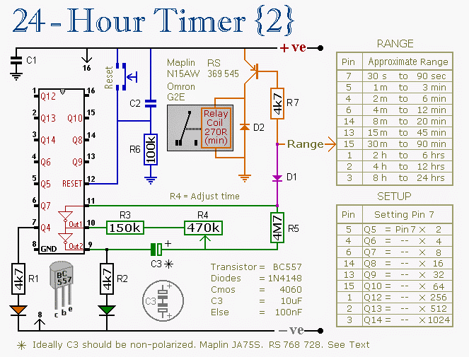
In this post we try to investigate a couple of innovative solutions which could be used for pausing the counting process of a timer IC during power failures, and also restart the process when mains is restored, ensuring a continuous functioning of the timer without errors. The idea was requested by Mr. Arun Dev.
Technical Specifications
I need a timer circuit which should activate a relay for the determined time interval and thereafter deactivate it until a manual operation is detected...
The main purpose of doing this circuit is to charge my laptop or mobile phone over night keeping it charging for a few hours ( say max. of 4 hrs ) only......
thereafter charging cut off immediately.... even though the main intention is for charging, i also want to integrate this to operate a particular electrical equipment as per user's time decisions....
This can easily be carried out using a relay to switch the AC voltage as seen in the attached figure.....
but the only one problem regarding this is that :
whenever a power failure occurs during its ( timer ) working period, the CD4060 IC automatically gets reset and the timer starts from beginning when power returns.....
SO ANY IDEA TO PAUSE THE WORKING ( COUNTING ) OF THIS IC DURING POWER FAILURE AND RESUME FROM THAT POINT WHEN POWER RETURNS TO MAKE SURE THAT THE CONNECTED EQUIPMENTS ARE WORKING ONLY IN THE USER DEFINED TIME ??
Circuit Diagram

The Design
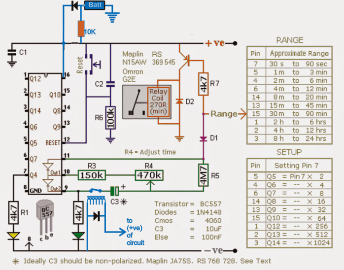
The modified version of the above 4060 timer circuit can be witnessed in the following schematic. The circuit includes an automatic pause and restart feature of the IC's counting process during power failures and restorations respectively.

The sections which are colored in blue are the inserted modifications, we can see a battery backup being added at pin16 of the IC via diodes, and a relay at pin9 of the IC.
Since the capacitor C3 is responsible for initiating the counting process of the timer while it gets fully charged, this component could be targeted for the intended pausing/resuming of the timer.
As may be seen in the diagram, this is simply implemented by connecting C3 to the "hot" pin9 of the IC via a pair of relay contacts (N/O to be precise).
However for making the above implementation work, the IC needs to be supplied with its fundamental operating current and voltage while the mains is not available.
This is done by adding a battery back up to the IC via isolating diodes at pin16 of the IC.
The associated 10K resistor makes sure that the battery keeps getting the required trickle charge as long as the mains continues to be present.
When power is first switched ON, the relay at pin9 activates and connects C3 in the line so that the IC is able to initiate normally and begin its counting process.
During Mains Failure
In an event of a mains failure,the battery takes over and keeps the IC powered in an uninterruptible manner, while also simultaneously the relay at pin9 of the IC disconnects C3 from the line in order to stop the capacitor from losing the stored instantaneous charge via pin9, this ensures that the elapsed time period gets locked inside the capacitor for that particular moment until the mains is restored.
The moment mains power returns C3 is connected back with the circuit by the relay, enabling it to resume the counting process exactly from where it had stopped and not from zero as it would otherwise do if the above mods weren't included.
The above could be also identically implemented in other timer ICs such as in IC 555 monostable circuit or IC 4047, IC 556 IC 4022 etc.
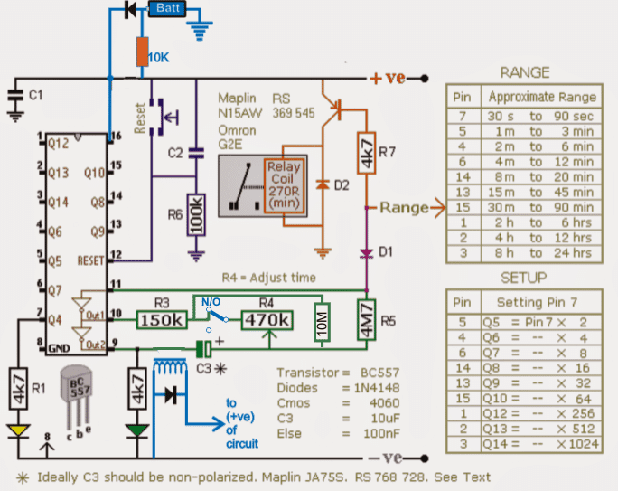
As discussed in the comments the above designs may have some limitations and flaws, a reasonable approach may be witnessed in the below given diagram which would hopefully allow minimum discrepancy, not more than 1% +/-. See the relay connection in blue across R4 and the inclusion of the high value 10M hold resistor.

Design#2: Timer Circuit with Memory
In this post I have explained a timer circuit programmed to cycle at 60 minute interval for watering the fields consistently. It also includes a time "memory" feature which ensures that the timer "remembers" the counting during mains failures, and restarts exactly from where it was interrupted when mains power is restored. The idea was requested by Mr. Siva.
I want to utilize the bore-well pump ground water based on online AC power supply.
stage 1:
1) Timer A start from zero end with 60 minutes(1 hour). 2) output power supply provided to stage 3 contractor coil. 3) Timer A should resume where it stop (e.g:stopped after 10 minutes successful running it should resume from 10 min until step 1 complete) 4) After 60 minutes completion it will stop & stage 2 will start running.
stage 2:
1)Timer B start from zero end with 60 minutes(1 hour). 2)Timer B will have inbuilt power supply(eg: AAA size rechargeable battery) 3)After 60 minutes completion it will stop & stage 1 will start running.
stage 3:
- 3 pole contactor used to allow the AC power supply. 2) Contactor coil power supply received from timer A circuit. ------------------------------------------------------------------- I) There is an frequent power failure in our area. II) Can't run the pump at an desired interval time period. III)For agriculture use only. IV) Pausing a timer during a power failure could be difficult using discrete components. V)suggest me any other components available in online. VI)I am ready to purchase it.
How it Works
The stage#2 timer circuit is perhaps not required since the stage#2 alone can be used for implementing the 60 minute ON/OFF cycle for the motor.
The main challenge in the design is the pausing of the timer IC such that the timer circuit is able to freeze itself during a power failure and initiate the timing from the same point as soon as the power is restored.
This seems a little complex since the IC might require some kind of memory feature to remember and retain the time period for which it was stopped due to a power failure.
However, with a simple trick it may not be so complex to implement the mentioned time pause effect, and could be done simply by cutting off one of the timing capacitor leads during mains interruptions, and then joining it back once the power came back.
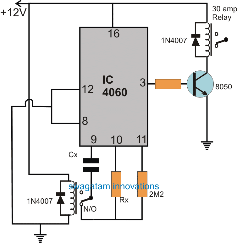
The following diagram shows the set up, which will hopefully be able to perform the intended pause effect in the timer circuit.
Circuit Diagram

The design is nothing but a simple IC 4060 timer circuit. The Cx, and Rx form its timing components, meaning altering the values of these proportionately alters the output frequency timing at pin#3 of the IC.
A low current relay can be seen attached with the timing capacitor of the IC whose contacts keep the capacitor connected with the circuit configuration during normal operations or when mains power is available. However in the absence of mains, this relay quickly cuts off the capacitor from the circuit.
Since the charge content inside the capacitor fundamentally determines the time delay periods across the outputs of the IC, disconnecting the capacitor enables freezing of the charge content inside the capacitor intact until the power arrives back.
As soon as power gets restored the IC reads and responds to the available charge inside the capacitor and initiates the counting from the same period onward where it had stopped. This system ensures that the IC resumes from the point where it was stopped due to the mains interruption.
The output pin#3 of the timer is connected with a 30 amp relay stage which may be configured with the contactor unit, for the necessary triggering of the pump and for watering the farm at the specified time intervals.
The timer circuit is designed to cycle ON/OFF with time delays as set by the values of the Cx and Rx, which may be calculated using the formula presented in this simple 4060 timer circuit article:


With over 50,000 comments answered so far, this is the only electronics website dedicated to solving all your circuit-related problems. If you’re stuck on a circuit, please leave your question in the comment box, and I will try to solve it ASAP!