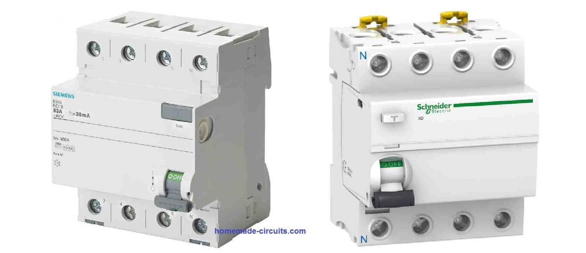
A Residual Current Circuit Breaker (RCCB) or a ground fault circuit interrupter (GFCI), is a form of circuit breaker which will shut down mains AC power as soon as it detects an discrepancy between the incoming current and the outgoing current, through it.

The primary objective of an RCCB device is to cut-off main AC and safeguard people from an electric shock. An RCCB will trigger and trip instantly, when it detects some current passing through an individual's body due to the body coming in contact with the mains AC line.
The device will also shut down when it detects some kind of an electrical error, for example a short circuit, insulation malfunction, or equipment breakdown.
Difference Between RCCB and MCCB
Common circuit breakers or MCCB (mains current circuit breaker) turn off mains AC power as soon as it detects an over current or an overload, for example over current in the range of 10, 15, or 20 amps.
However, a minuscule current 0.030 amps getting through a human body can be enough to cause a skeletal paralysis of muscles, or trigger a human heart attack.
An RCCB is designed to disconnect or break the circuit the moment it detects an small imbalance even by a magnitude of 0.005 amps (0.030 amps in Australia and some European and Asian countries).
An MCCB or other forms of circuit breaker protects your home wires and equipment from overheating and probable fire hazards.
An RCCB provides protection to people from electric shocks and electrical fatality and can be generally seen fitted in bathrooms or kitchens. Because these are the places where electrical devices are mostly in direct contact with the people, and chances of an electrical shock through current passing from the device to human body and ground is maximum in such locations.
A RCCB can furthermore protect against fire hazards due to electrical short circuits and other electrical malfunctions that don't usually include humans, for example a low current short in which the current may never extend to the tripping level for a circuit breaker, this may include a live wire dropping in a water bucket or humid soil, allowing the passage of just 0.1 or 0.2 amps of current.
RCCB Basic Operating Principle
RCCB basically operates using the Kirchhoff’s law, according to which an incoming current is always identical to the outgoing current in any form of circuit. Using this principle, an RCCB compares and analyzes the difference in the magnitudes of the current across the phase and the neutral wires.
Normally, the current passing to the load through the live wire will be always the same to the amount of current returning back through the neutral wire. When some kind of electrical fault happens due to leakage on the live side wire, the returning current to the neutral line is reduced.
This causes a difference of current between the incoming live wire and the outgoing neutral wire. This difference of current is called the Residual Current, and is used in RCCB for detecting an electrical fault. As soon as this Residual Current is detected, the RCCB is instantly activated to trip and break the circuit.
A push button testing facility is provided in all Residual Current devices so that the reliability of the device can be verified by the user anytime it needs to tested.
In this procedure when a test push button is pushed, it bypasses a small amount of current across the live side of the RCCB circuit. The situation causes an imbalance to trigger on the neutral side of the RCCB device, which in turn forces the RCCB to trip and cut-off the circuit, and in so doing it confirms the working reliability of the device.
How RCCB Device or (RCD) Works
An RCD works by using the principle in which current running through the conductors or winding of its summation current transformer are compared.
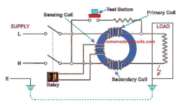
As shown in the image below, an RCCB device is made up of a current transformer having 3 types of winding on it, primary winding, secondary winding and the sensing winding:

The main phase line or the LIVE line is supplied to the input of the primary winding, while the neutral line is connected with the input of the secondary winding. The third winding which is called the sensing coil is wound between the above two winding, and is terminated for connecting with the relay coil.
The relay is a permanent magnet type relay which has a normally closed contacts. Meaning its contracts are normally closed in the absence of a fault or leakage.
During normal circumstances when there's no phase-to-ground fault, the instantaneous current or the vectorial sum of the current on the sensing winding of the current transformer is almost zero.
However, during an earth leakage or human contact with the LIVE wire, some portion of the current begins flowing away from live line of the winding, that produces an imbalance condition in the sensing current transformer.
Due to this imbalance, a resultant magnetic flux induces an excitation field within the current transformer core, which in turn causes an equivalent current to be generated inside the sensing coil.
This current in the sensing coil eventually actuates the trip relay or the permanent magnet relay (PMR) providing the intended impulse to trip the contacts of the RCD or the RCCB, so that the contacts are instantly released and the mains supply is broken.
Summation Current Transformer or CT
The current transformer (CT) is generally manufactured in the form of a ring-shaped or torroidal transformer. The magnetic material used for the transformer is usually Permaloy; while many modern variants work with a exclusive magnetic materials using nanocrystalline structure.
How the Trip Relay Works
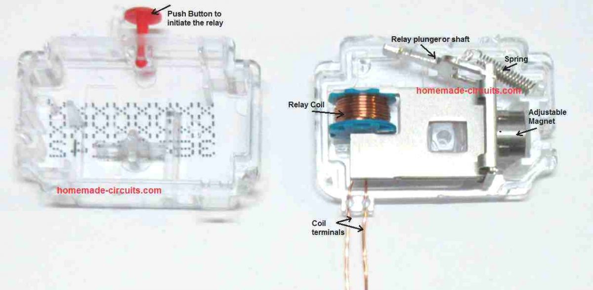
The relay used in RCCB is mostly a permanent magnet type or PMR type, in which core is made up of a permanent magnet as shown in the figure above. In quiescent state or during an absence of a residual current fault, the relay armature or the relay shaft is consistently pulled by the magnet and held tightly ON.

The magnetic force keeps the shaft tightly attracted towards it even while the spring force acts on the opposite direction. This condition causes the external mechanism to keep the mains live line and neutral line switched ON so that the load and rest of the wiring can operate normally.
In case a residual current leakage is detected, maybe due to an electrical shock to a human body, the current from the sensing coil of the transformer causes a repelling or opposing magnetic field to be induced on the PMR coil which leads to a weakening of the permanent magnet attraction over the relay shaft, and this allows the spring force to pull away the relay armature or the relay shaft open, in the original position.
When this happens, the external mechanized contacts or the integrated switching contacts are also opened quickly, which disconnects the mains line breaking the circuit, ensuring safety to the target from the dangerous situation.
Because of its simplicity and confirmed reliability, this form of permanent magnet relays or polarized relays are widely used in most RCD or RCCB applications.
Swithing Mechanism
The switching mechanism of the RCD should be very sensitive as and also should be able to deliver adequate pressure on the contacts. Efficient functionality has to be guaranteed in every construction assemblies. Each and every current route to the load should be effective at supplying the minimal required amount of current for the complete lifetime. The length across circuit breaker contacts should possess risk-free electric insulation and contacts should be shielded against surge currents and short-circuits, with a precalculated short-circuit current.
It is additionally mandatory that for multi-polar types of contacts, the neutral contacts should close before the LIVE line contacts, and the neutral contacts should open after the LIVE line contacts. The will prevent unnecessary surge voltage spikes in the electrical system.
Test Button
All RCD or RCCB units should be furnished with a testing circuitry which must include a test button T (Test) and a resistance R, depending on on the operating voltage. The test button should be easily and quickly accessible to the user. When this test button is pushed, an sample residual current is simulated through the test resistor R, resulting in some low amount of current to move out of the summation transformer, which causes the relay to trip and break the circuit.
RCCB Parameters
Rated residual operating current IΔn : It is the amount of residual current as specified by the company. The value tells us exactly under what specific conditions the RCCB unit must break the circuit. This value is printed on the circuit breaker body along with the associated working characteristics. It is the most important parameter of any RCCB, which specifies the conditions related to security against dangerous human contact with electricity.
• Residual current IΔ (differential current): It is the effective value of instantaneous current values that passes through the main circuit of the RCCB. IΔ can be any amount of current lower or equal to or higher than IΔn
. • Residual non-tripping current IΔno: It is the amount of residual current, in which (which includes lower values), the RCCB device, under the specified conditions, should not trip or actuate. This is characterized by the tolerance threshold of 0.5 IΔn . The amount of non-operating and operating residual current thresholds are usually fixed at the manufacturing test lab itself, to around 0.75 IΔn
. • Limit non-operation time tΔa (time delay): It is the maximum time the circuit breaker may be allowed to keep operating with some elevated value of residual current than the moderate residual current value IΔn , without causing an activation of the RCCB.
This residual current value enables RCCB units with a tripping delay time (for type G, the threshold of non-operation time is 10 ms, and for type S it can be around 40 ms). During the time the RCCB is in the non-operational period, the device remains unresponsive to the residual currents.
Experimental Circuit
Warning: This RCCB experiment is recommended only for the experts, who know how to cautiously handle 220V or 120 V mains voltage based circuit. The following experiment involves direct ac mains voltage and is therefore extremely dangerous to touch while experimenting.
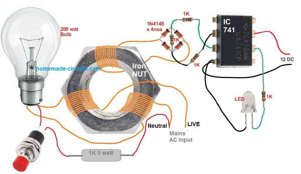
An experimental setup to understand the RCCB working is depicted in the following circuit diagram:

The objective of this RCCB circuit experiment is to illuminate an LED as soon as an imbalance is detected within a current transformer.
The current transformer is built by winding the primary, secondary and the sensing winding over a large iron nut,
Make sure the nut is adequately insulated with insulation tape before the winding is implemented.
The 3 winding can be of identical number of turns, maybe 100 turns each, using 0.2 mm or 0.3 mm super enameled copper wire, which can be extracted from any burnt 1 amp transformer secondary winding.
The left side winding acts like the primary winding, the right side winding acts like the secondary winding, while the top center winding works like the sensing coil.
A bridge rectifier is used for rectifying the residual AC from the sensing coil, using 1N4148 diodes, so that the resulting DC can be used for further amplification using an op amp circuit.
A 741 op amp is set up like a differential amplifier. It is configured to detect the voltage developing from the sensing coil when the test button is pressed.
Once the whole RCCB experimental circuit is built and set up. Switching ON the mains AC into the current transformer will operate the 200 watt bulb normally and the op amp LED will remain shut off, indicating an absence of any fault, and an equilibrium across the LIVE and the neutral winding currents.
However, when the test button (red push button) is pressed, a small amount of current will start leaking from the load (bulb) to the neutral line, causing an imbalance across the primary and the secondary wining on the nut.
This will generate a resultant error magnetic flux on the nut iron, which will in turn cause an equivalent small AC voltage to be induced on the sensing coil.
This small AC generated across the sensing coil will pass through the bridge rectifier and cause a potential difference to be generated across the 1K resistor inserted between the 1N4148 diode bridge.
This potential difference will be detected by the differential op amp, causing the op amp output to become high. and illuminate the connected LED.
The illuminated LED will indicate the presence of a leakage current across the line, which may be equivalent to a fault occurring due to a shock current passing through a human body
Hi Swagatam,
Why rccb’s available in market are so costly whereas if we see the value of components used in making it shouldn’t be that costly e.g. a 40A , 30ma, DP rccb of Havells cost around 2500 rupees.
Hi Rana,
Commercial RCCBs are built with high precision and ensure all laid down protocols are taken into consideration, and moreover they have high overhead costs and have to provide warranties. Due to all these combined criteria the cost price increases significantly.