The simple programmable humidity sensor circuit I have explained in this article can be used for controlling or maintaining a suitable level of humidity inside a close premise.
The circuit could be used in poultry farms or similar areas where humidity level becomes crucial for keeping the animals healthy. The idea was requested by Mr. Tanvir
How it Works
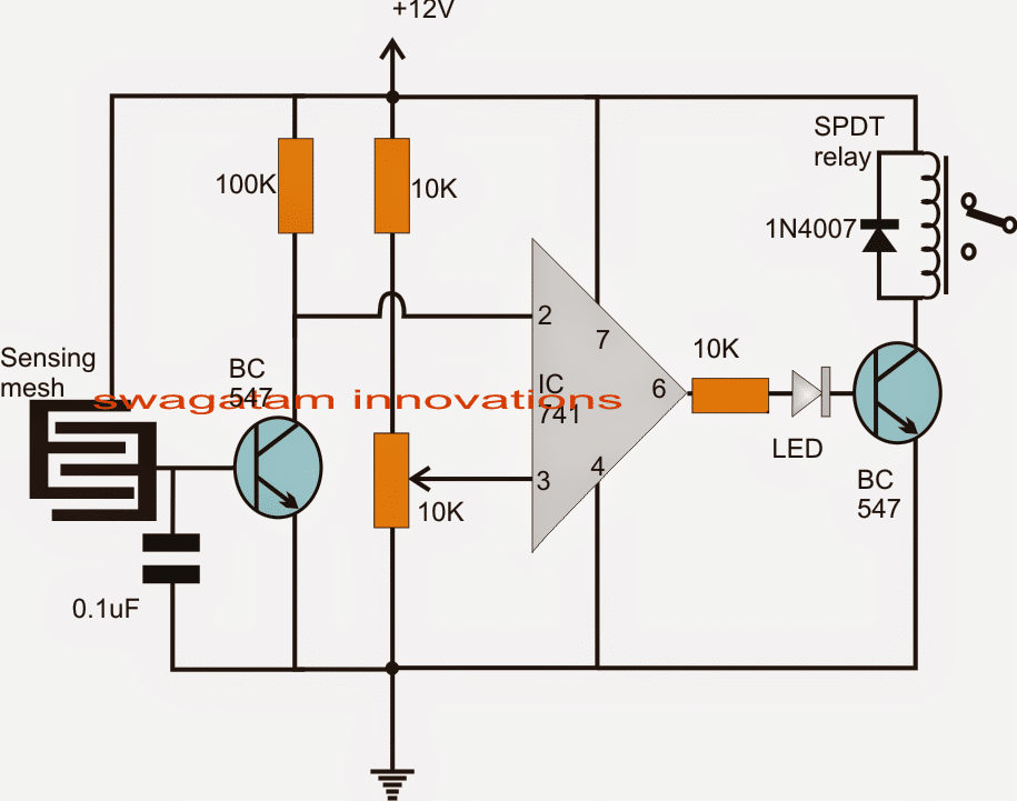
Referring to the proposed humidity sensor, controller circuit, we find the design to be dependent on a single opamp module configured as a comparator.
Pin3 of the IC which is the non-inverting input of the IC is held with a predetermined reference level set by the 10k preset.
Pin2 of the IC is held at the supply potential via the 100k resistor.
This pinout is also connected to the collector of an NPN transistor.
The base of the NPN is connected to a conductor mesh separated by another mesh which is connected to the positive supply of the circuit.
The separation of the two meshes are optimized over a close proximity such that the humidity content is able to bridge the gap sufficiently during optimal levels and vice versa.
When power is switched ON initially, the humidity is allowed to increase in the premise by spreading water through a very fine water sprayer. This is done through a device connected to the relay of the circuit in the N/C position.
As the humidity increases depending on the level of humidity and the setting of the 10k preset, the base of the NPN transistor tends to get saturated and in case the level exceeds the predetermined threshold the transistor conducts.
This pulls and brings pin2 potential toward ground level.
The above action allows pin3 of the IC to attain a more positive potential than at pin2, prompting the output to become high.
The high output now triggers the relay driver stage, switching OFF the connected water sprayer.
As long as the humidity level within the area stays above the set threshold, the relay holds its position and keeps the sprayer switched off.
However the moment the humidity level tends to get lower below the required point, the operations are instantly triggered and repeated making sure that the humidity level never gets too low or too high inside the chamber.
Circuit Diagram

Sensor Specification
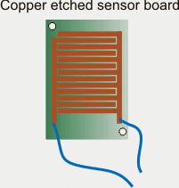
The sensor can be made by etching a copper clad PCB in the following manner:

Using Glass as the Sensor
The coper mesh shown above seems to have a drawback, the mosture trapped within the copper lines could turn into water droplets and clog the mesh causing a permanent switch ON for the relay.
A smarter way of sensing moisture could be by using a glass and an LDR for the detection. To implement it practically with the circuit, the following changes could be made in the above design.
1) remove the BC547 transistor and its base componets.
2) connect a refernce zener across pin#2 and ground.
3) replace 10K with a LDR, and configure an LED and a clear glass such that the light from the LED falls on the LDR through that glass.
Now as long as the mositure level is low, the glass stays clean and allows maximum light for the LDR causing the relay to switch ON and spray the mist.
As soon as the moisture level increases above the set threshold level, the glass gets obscure enough causing pin#3 potential to fall below pin#2, and switching OFF the relay, until the glass again becomes clear.


With over 50,000 comments answered so far, this is the only electronics website dedicated to solving all your circuit-related problems. If you’re stuck on a circuit, please leave your question in the comment box, and I will try to solve it ASAP!